Abstract
The cavity plays an important role in the fuel-air mixing and combustion stability inside the hypersonic scramjet. However, the high levels of time-dependent loading resulting from the supersonic cavity flow can cause intense structural vibration even damage. Experiments and numerical simulations were performed to understand the complex fluid-structure interaction in this paper. A cantilever plate with a cavity was installed as a splitter plate in the supersonic mixing layer wind tunnel. The response displacements of this cantilever plate were measured by a non-intrusive laser vibrometer. Large eddy simulation (LES) was applied to calculate the aerodynamic loading. Results show that the number of time-dependent surface-averaged pressure difference agrees well with semi-empirical relation of Heller used to predict the resonance mode. The cantilever plate exhibits a directly dependent response to self-oscillation of supersonic cavity flow. Measurement results of displacement indicate that the vibration shape of this plate is dominantly two-dimensional.
1. Introduction
The cavity is one of the most popular devices in the scramjet combustor due to the excellent behavior in stabilizing the flame [1] and mixing enhancement [2, 3]. In the supersonic cavity flow, self-oscillation [4, 5], the nature characteristic, results in the time-dependent aeroacoustic loading on the structure. The structure vibrates when its natural frequency is motivated due to the large broadband of this loading. This may cause the fatigue of structure and reduce its life span even damage directly. The possibility for damage of cavity structure is high but the aeroacoustic-structure coupling mechanism for vibrations is seldom reported in the past researches to the authors’ knowledge.
Many researchers have focused on the aeroacoustic loading of the supersonic cavity flow in the past decades [6-8]. The Strouhal number (St) of self-oscillation can be predicted by Rossiter’s semi-empirical formula [9] which is then modified by Heller [10]. However, energy distribution is found difficult to predict owing to the complex function of many factors. Numerical results indicate that the second and third self-oscillation mode contain the most energy [5]. Although characteristics of supersonic cavity flow and aeroacoustic loading [11, 12] have been widely understood, only several studies concentrate on the flow-induced vibration. Wang X. S. [13] found that structural vibration frequency is close to natural frequency of the cavity structure and the lower mode dominates vibration behavior. The power spectral density of structural vibration is close correlated with that of cavity aeroacoustic noise. Justin L. W. [14, 15] conducted experiments to understand the fluid-structure interaction (FSI) in the aircraft internal store carriage from subsonic to supersonic flow. The store responds to the cavity flow at its natural frequency and it is close associated with self-oscillation of the cavity. Understanding the coupling mechanism of structural vibration and aeroacoustic loading is significant to evaluate the design of cavity geometry parameters. However, little results can help with this problem.
The objective of this paper is to study the flow-induced vibration characteristics and explore the coupling mechanism in the compressible cavity flow through experimental and numerical methods.
2. Experimental and numerical methods
Experimental studies were performed in the suction supersonic mixing layer wind tunnel, as sketched in Fig. 1. Two supersonic flows are generated by the double Mach number nozzle due to the pressure difference between vacuum tank and ambient air. Calibrated Mach numbers are 1.98 and 2.76 for upper and lower sides respectively. The detailed parameters are listed in Table 1. A splitter plate with a cavity made of structural steel was mounted in the centerline of the nozzle to separate the two different speed supersonic flow. The cavity with depth () of 4 mm and length () of 20 mm can induce vibration of this splitter plate due to its self-oscillation. The part-1 of splitter plate is fixed in both sides by two slots inside the double Mach number nozzle. The part-2 can probably be considered as a cantilever plate. The length to depth ratio is defined as .The vibration displacements are measured by a single point laser vibrometer produced by Julight, Italy. Ref. [16] introduces this device in detail. It can measure the quite small displacements at 0.1 nm and does not take disturbance into the supersonic flow. The four fixed rods located in the test section of wind tunnel can be screwed into the supersonic flow. The distance between plate surface and fixed rod can be adjusted by moving up and down.
Fig. 1The schematic of experimental system
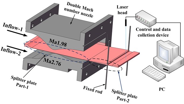
Table 1Parameters of incoming flow
Ma | Total pressure / Pa | Static pressure / Pa | Mc | |
Inflow-1 | 1.98 | 29872 | 3940 | 0.18 |
Inflow-2 | 2.76 | 101325 | 3969 |
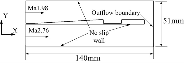
Large eddy simulation (LES) was conducted to obtain the aeroacoustic loading of upper and lower surface of the splitter plate. Details of this numerical method can be consulted in Ref. [5] and many past researches have indicated that this code is competent in predicting main features of supersonic cavity flow. The calculation model, shown in Fig. 2, is simplified from experimental devices and inflow conditions coincide with counterparts in the experimental studies. Notably, the spanwise and streamwise size are set only 30 mm and 80 mm respectively to cut calculation resource consume. Viscous fluxes are solved by the fourth-order central difference scheme and the fifth-order WENO (Weighted Essentially Non-Oscillation) scheme is applied to discretize inviscid fluxes. In order to enhance efficiency, the third Runge-Kutta that possesses the TVD characteristic has been used for time integration. The Courant-Friedrichs-Lewy(CFL) number is set 0.5 along the calculations and structured grids are used for the whole zone. The size of first grid close to walls must be ensured in order to get accurate results.
Fig. 2The schematic of calculation model
3. Results and discussion
3.1. The aeroacoustic loading on the splitter plate surface
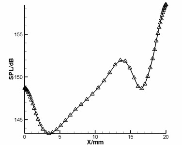
Self-oscillation accompanying with high frequency pressure fluctuation is the main behavior in the compressible cavity flow. The self-oscillation results from the interaction between the cavity shear layer and cavity wall. The cavity shear layer impinges on the aft wall and pressure wave returns back through the cavity. When the pressure arrives at the leading edge of cavity, it will couples with shear layer and push it separation from the wall. Fig. 3 shows the sound pressure level (SPL) inside the cavity, which is computed by Eq. (1):
where the reference pressure is 20 μPa. It is the fiercest at 20 mm, namely the position of aft wall. A peak value also appears in the front wall but is much smaller than the SPL of aft wall. This means a faint impingement between pressure back wave and front wall.
Fig. 3The sound pressure level distribution along the streamwise in the cavity
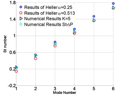
The (Strouhal number) is usually applied to characteristic self-oscillation, which can be obtained by Heller’s relation [10] as shown in Eq. (2). In this formula, is the upper free stream, is the free stream Mach number, is the cavity length, and are empirical constants. In Fig. 4, numerical numbers obtained by LES for 5 show a good agreement with Heller’s results. The value choices of 0.25 and 0.513 are suitable for the prediction of lower and higher mode respectively. The of surface-averaged pressure difference between upper and lower surface, considered as the loading for vibration, is the same as the numerical results for 5. This fact indicates that the aeroacoustic loading on the splitter plate surface is absolutely determined by the supersonic cavity flow:
Fig. 4Comparison for the St number of Heller’s and numerical results
3.2. Vibration characteristics
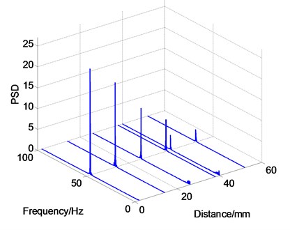
In order to explore the vibration characteristics, six and three test points are distributed on surface along the streamwise and spanwise respectively and displacements are collected from them, as sketched in Fig. 5 and Fig. 6. In this section, the gap distance between splitter plate surface and fixed rod is 1 mm. The frequency fixes in 51 Hz among the six test point along the streamwise, as illustrated in Fig. 6. The largest PSD corresponds with the first test point located 2 mm away from the end edge of cantilever plate. Then it decreases gradually with the increase of distance. On the whole, the PSD is linearly distributed along the streamwise. Displacements of two points located inside the cavity are similar with others even if cavity plate is thinner and has smaller rigidity.
Fig. 5The test points distribution along the streamwise
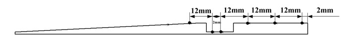
Fig. 6Vibration frequency and PSD distributions along the streamwise
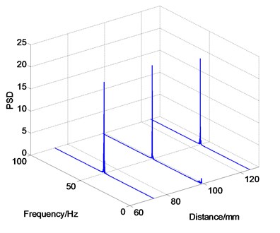
As shown in Fig. 7, three test points are distributed along the spanwise and the second one is in the centerline of the splitter plate. Data indicate that the frequency also fixes in 51 Hz and their PSDs are nearly absolute equal, as displayed in Fig. 8.
Analysis above has proved that vibration shape is simple and mainly in two-dimensionality
Fig. 7The test points distribution along the spanwise
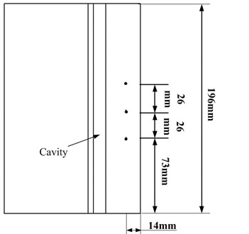
Fig. 8Vibration frequency distribution along the spanwsie
4. Conclusions
In this paper, the flow-induced vibration in the compressible cavity flow is studied through experimental and numerical methods. The following two significant conclusions can be drawn from analysis above:
1) The features of supersonic cavity flow dominate the vibration of the splitter plate directly. Aeroacoustic loading comes from the self-oscillation inside the cavity.
2) The vibration mode of splitter plate focuses on lower-order and is two-dimensional. This can be proved by the vibration displacements along the streamwise and spanwise.
References
-
Gruber M. R., Baurle R. A., Mathur T., Hsu K. Y. Fundamental studies of cavity-based flame holder concepts for supersonic combustors. Journal of Propulsion and Power, Vol. 17, 2001, p. 146-153.
-
Handa T., Nakano A., Tanigawa K., Fujita J. Supersonic mixing enhanced by cavity-induced three-dimensional oscillatory flow. Experiments in Fluids, Vol. 55, Issue 4, 2014, p. 1-10.
-
Yu K. H., Schadow K. C. Cavity-actuated supersonic mixing and combustion control. Combustion and Flame, Vol. 99, Issue 2, 1994, p. 295-301.
-
Cattafesta L., Williams D., Rowley C., Alvid F. Review of active control of flow-induced cavity resonance. AIAA 3567, 2003.
-
Wang H., Sun M., Qin N., Wu H., Wang Z. Characteristics of oscillations in supersonic open cavity flows. Flow, Turbulence and Combustion, Vol. 90, Issue 1, 2013, p. 121-142.
-
Heller H. H., Holmes D. G., Covert E. E. Flow-Induced Pressure Oscillations in Shallow Cavities. Journal of Sound and Vibration, Vol. 18, Issue 4, 1971, p. 545-553.
-
Mongeau L., Kook H., Franchek M. Active control of flow-induced cavity resonance. AIAA/CEAS Aeroacoustics Conference, 2013.
-
Ukeiley L. S., Ponton M. K., Seiner J. M., Jansen B. Suppression of pressure loads in cavity flows, AIAA Journal, Vol. 42, Issue 42, 2012, p. 70-79.
-
Rossiter J. E. Wind-Tunnel Experiments on the Flow Over Rectangular Cavities at Subsonic and Transonic Speeds. RAE Technical Report No. 64037, Ministry of Aviation, Royal Aircraft Establishment, RAE Farnborough, 1964.
-
Heller H. H., Bliss D. B. The physical mechanism of flow induced pressure fluctuations in cavities and concepts for their suppression. AIAA 75-491, 1975.
-
Coley C., Lofthouse A. Correlation of weapon bay resonance and store unsteady force and moment loading. AIAA Aerospace Sciences Meeting Including the New Horizons Forum and Aerospace Exposition, 2013.
-
Barone M. F., Arunajatesan S. Pressure loading within rectangular cavities with and without a captive store. Aerospace Sciences Meeting, 2013, p. 670-673.
-
Wang X. S., Yang D. G., Liu J., et al. Experimental study of interactions between aeroacoustic noise and structural vibrations in an elastic cavity flow. Acta Aeronautica et Astronautica Sinica, Vol. 37, 2017, p. 120873.
-
Wagner J., Casper K., Beresh S., Hunter P., Spillers R., Henfling J., Mayes R. Experimental investigation of fluid-structure interactions in compressible cavity flows. AIAA Fluid Dynamics Conference, 2013, p. 471-479.
-
Wagner J. L., Casper K. M., Beresh S. J., Hunter P. S., Spillers R. W., Henfling J. F., Mayes R. L. Fluid-structure interactions in compressible cavity flows. Physics of Fluids, Vol. 27, Issue 6, 2015, p. 152-165.
-
Giuliani G., Bozzipietra S., Donati S. Self-mixing laser diode vibrometer. Measurement Science and Technology, Vol. 14, Issue 1, 2003, p. 24-32.
About this article

