Abstract
The circular cylinder with porous materials coating (PMC) is studied in detail to reveal the sensitivity of surface permeability to the flow control and noise reduction. Two-dimensional simulations were firstly used to identify the critical values of permeability and thickness. Parametric study results show that, there is a critical permeability value which produces the minimum force fluctuation and maximum noise reduction. Additionally, the porous coating can work more efficient for noise reduction with larger thickness. The further three-dimensional simulation is employed to understand the underlying physical mechanisms of flow control. The results show that the spanwise vorticity is modified more than that of other directions and behaves more synergistically. The pressure field adjacent to the cylinder surface indicates that the adverse pressure gradient is changed to the favorable pressure gradient around the porous surface which contributes partly to the vortex shedding suppression.
1. Introduction
Flow past circular cylinders has been extensively investigated in fluid dynamics associated with engineering application of aircraft landing gear system, pantograph of high-speed trains, heat exchangers etc. The cross-flow interaction with the cylinder induces unsteady loading on the surface which can cause serious structural and environmental problems, such as noise radiation, drag and vibration.
Passive flow control is an efficient approach to mitigate these adverse effects [1]. Porous media has potential benefits for flow-control [2, 3] through introducing a fluid permeable medium between the fluid and solid and modify the boundary layer and wake characteristics. A number of researchers have studied flow pass and through porous bluff bodies to reveal the interesting flow control phenomenon. Some of them focus on the low Reynolds flow aiming at e.g. enhancing heat transfer [4-6]. The high Reynolds flow is associated to the applications such as drag reduction, vibration and noise reduction. For example, Bruneau and Mortazavi [7] found that porous wraps around rectangular cylinders with suitable choice of permeability coefficient can potentially reduce the hydrodynamic drag by up to 30 %. Zhao et al. [8] and Yu et al. [9] performed numerical simulations for a porous cylinder and found that the drag reduction can be obtained using porous treatment dependent greatly on materials property and Reynolds number. Experimental [10] and numerical studies [11, 12] have also shown that the porous coatings can stabilize the shear layer and the near wake region and subsequently cause significant reduction in lift fluctuations and noise. It is attributed partly to the existence of slip boundary condition at the porous-fluid interface and dissipation of energy by the porous media. More recently, PIV (Particle Image Velocimetry) measurements have revealed again that perforated cylinders can elongate the shear layer and prevent the Karman Vortex Street [13]. Through acoustic measurements, Geyer et al. [14] found that the use of soft porous covers for circular cylinders can lead to noticeable aerodynamic noise reduction. Syamir et al. [15] experimentally found that the porous cover can reduce the fluctuating force of bluff body significantly and delay the vortex shedding and increase the formation length. Liu et al. [16] and Yamamoto et al. [17] investigated porous-cover concept for noise reduction of bluff-body component of landing gear and showed the promising results. However, the sensitivity and critical values of some important parameters of porous materials coating, such as typically permeability and thickness, for circular cylinder flow control and potential noise reduction, were not identified clearly by the previous studies. Also, to better understand the underlying mechanisms, more systematically researches are necessary.
For this reason, the present paper reports some important results of our study on the use of porous coatings for controlling the flow field of circular cylinder and reduction of the flow-generated noise. In particular, parametric study indicates the significance of the permeability constant for effective control of the unsteady aerodynamic features and far-field noise. The critical values of permeability and thickness are also studied systematically. The present study also contributes to reveal more underlying physical mechanisms, e.g. adverse pressure gradient medication. This paper is organized as follows. Section 2 presents the methodology used for the simulations. Section 3 is devoted to the results of parametric study. Section 4 gives the results of three-dimensional simulation for understanding the mechanisms of flow control. Results are presented for the unsteady aerodynamic forces, wake development and also the far-field noise. Section 5 concludes the critical values of porous coating parameter and the important control mechanisms.
2. Numerical methodology
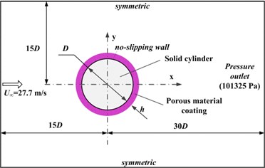
This paper considers the case of a single circular cylinder with diameter of 0.025 m, wrapped by a porous layer with thickness , placed in the uniform air inflow (density 1.225 kg/m3, viscosity 1.79×10⁻⁵ kg/(m·s)) at 4.7×10⁴, as shown in Fig. 1. Although the flow in this problem is intrinsically three-dimensional, as demonstrated in some prior research [18, 19], two-dimensional unsteady CFD can reveal some important aspects of flow-porous interaction, particularly the dynamics of vortex shedding and effects of unsteady aerodynamic forces. The related validation for two-dimensional simulation can be found in Ref. [20], where the numerical method has also been compared against the available data in other numerical and experimental investigations [21-24]. So, to balance the huge computing cost and parametric study aims, with some degree of accuracy, a number of two-dimensional simulations are implemented firstly. Subsequently, specific three-dimensional simulation is employed to reveal more underlying information to better understand the physical mechanisms of flow control by porous coating. The combination of two and three-dimensional simulation is a common strategy for investigating passive flow control [11].
The incompressible Navier-Stokes equations were solved using the finite volume CFD package of ANSYS-Fluent [25]. Large eddy simulation (LES) with smagorinsky subgrid model is employed to calculate the flow field. All current computations were performed with second-order accuracy. The computation domain and the boundary conditions are also shown in Fig. 1. The dimensionless time-step for unsteady simulation is 0.05, which is corresponding to 110 time-steps per vortex shedding cycle for sufficient resolution of shedding process. The present unsteady time step produces the maximum acoustics frequency up to 10 kHz which is enough for the present problem. The Brinkman-Forchheimer extended Darcy model is used to describe the mass and momentum conservation in the isotropic and homogeneous porous medium, similar to Vafai [26] and Hsu and Cheng [27]. The continuity condition is employed to couple the interface flow between the fluids outside and inside porous media. Further details of the simulation method can be found in Ref. [12]. In this paper, the Darcy number is used as non-dimensionalized permeability and the porosity () is set to 0.97. The relationship of permeability to other parameters, such as porosity and microscopic structure of the porous medium, is not the focus of this paper. Ffowcs Williams-Hawkings (FW-H) equation with integral solution [28, 29] are used to predict the far-field noise. The acoustics integral surface is defined on the porous surface.
Fig. 1Schematic of flow past the circular cylinder with porous materials coating
3. Sensitivity study of permeability and thickness
3.1. Unsteady force fluctuation and drag
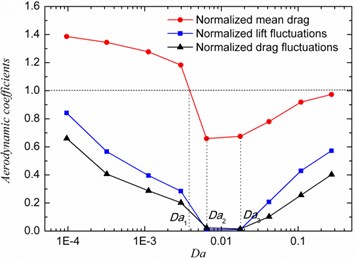
The effect of porous coating permeability and thickness on the effective control of the unsteady forces acting on the cylinder is presented in Fig. 2. The RMS (Root-Mean-Square) force coefficients and time-averaged drag coefficient are normalized with the value of rigid cylinder (baseline). In Fig. 2(a), the dimensionless porous coating thickness is fixed at normalized value of 0.80, where . Fig. 2(a) shows that both the lift and drag fluctuations and mean drag reach their minimum when the dimensionless permeability is between 6.4×10⁻³ and 1.8×10⁻². It is considered here the critical value to be approximately 6.4×10⁻³, because that is close to Naito and Fukagata’s value of 2.0×10⁻² [11]. The permeability deviating from the critical value causes the degenerative flow control effects. The porous materials coating (PMC) with extremely high permeability behave similar to a pure fluid medium and therefore the unsteady forces and drag level should gradually approach the level of the baseline case. In the permeability range considered in this study, the lift and drag fluctuations of the treated cylinders are always lower than that of the baseline. When the permeability is proper e.g. larger than 3.5×10⁻³ as seen in Fig. 2(a), the drag level seems to be reduced compared with baseline value. Fig. 2(b) presents the influences of the porous coating thickness (). Based on the results in Fig. 2(a), the dimensionless permeability is set to 6.4×10⁻³. Results have shown that the unsteady forces on the cylinder can be significantly reduced by adding a porous coating on the cylinder. Results indicate that the mean drag force can be decreased if a relatively thicker porous layer is used (i.e. 0.48). Seen from the results, even a very thin porous layer (i.e. 0.05) can lead to an increase in the mean drag force, because of the change of surface condition and the porous intrinsic drag force. However, when the extreme thickness of porous layer reach zero, the drag level should be equal to that of baseline. The rapid drop observed during thickness changes from 0.48 to 0.64, indicates significant changes of flow structure which was also investigated in prior investigations [12, 20].
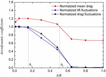
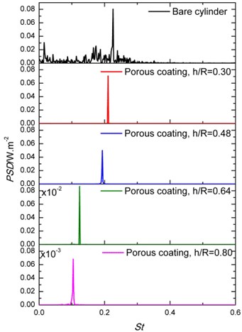
Fig. 3 shows the power spectrum density (PSD) of the lift fluctuations for cylinders treated with porous materials with different permeability () and thickness (). The dimensionless frequency is . Fig. 3(a) shows that the lift PSD reduction depends strongly on the permeability of the porous material. In addition, the dominant vortex shedding frequency is reduced to about 0.1 when permeability of porous coating is 6.4×10⁻³. Furthermore, results in Fig. 3(b) show that increasing the thickness of the porous layer leads to a significant decrease of the lift fluctuation energy and associated frequency, when the non-dimensional permeability is fixed at 6.4×10⁻³. The PSD results at and 0.64 show even energy attenuation of two orders. The recent work [30] of using plasma to control the tandem cylinder flow also reports similar dramatic peak value reduction of PSD up to two orders. Here, it is explained as the significant vortex shedding suppression in terms of vorticity energy dissipation and frequency reduction which can see in the later flow results.
Fig. 2Unsteady forces fluctuation and drag for a cylinder with porous coating: a) Cylinder with h/R= 0.8 over a wide range of Darcy number, b) Effect of varying the coating thickness at Da= 6.4×10⁻³
a)
b)
Fig. 3Power spectral density of the lift coefficient of cylinders covered with porous material: a) The effect of Darcy number at constant h/R= 0.80 and b) the effect of porous coating thickness at Da= 6.4×10⁻³
a)
b)
3.2. Effects on flow behavior
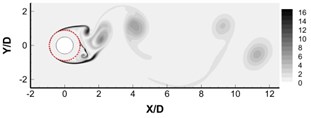
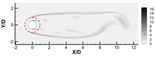
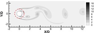
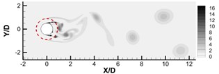
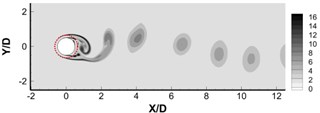
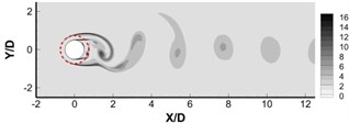
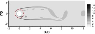
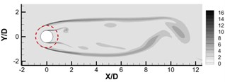
To better understand the aerodynamic results presented in Section 3.1, the flow field results are given in this section. The instantaneous spanwise vorticity fields of cylinders covered by porous layer of different values are shown in Fig. 4. The solid and dashed lines represent the solid surface and the porous surface, respectively. The non-dimensional thickness () of porous layer is set to 0.8. In Fig. 4(a), it can be seen that when the permeability is quite small ( 9.6×10⁻⁵), the porous materials behave more like solid, and intense vortex shedding happens from the surface of the porous coating. Fig. 4(d) shows that, in contrast, when the permeability is quite large ( 0.272), the porous materials behave more like pure fluid and intense vortex shedding appears around the inside solid cylinder. Fig. 4 shows that the vortex shedding formation and turbulence level in the near wake can be effectively controlled by employing a porous material cover with an optimum permeability value. It can be seen in Fig. 4(b) that the initial roll-up location can be moved downstream to position of several diameter (almost 8) using an optimum permeability. According to the studies of Lam and Lin [31] on waved-surface cylinder, the elongated vortex formation length consequently can contribute to the pressure-drag reduction which demonstrates the result in previous Fig. 2. The porous coating is also found to decrease the vorticity intensity within the wake, which is consistent with the recently experimental reports of perforated cylinders [13]. The instantaneous spanwise vorticity field for cylinders with different thicknesses are shown in Fig. 5, where the permeability value is fixed at 6.4×10⁻³. With the increase of porous cover thickness, the free shear layer extends further downstream and rolls up weakly. Significant changes can be observed between Fig. 5(b) and Fig. 5(c), when the porous coating thickness increases from 0.48 to 0.64.
Fig. 4Instantaneous dimensionless vorticity contours 0 ≤ωzD/U∞≤ 16 for a) Da= 9.6×10⁻⁵, b) Da= 6.4×10⁻³, c) Da= 4.16×10⁻², d) Da= 0.272. The non-dimensional thickness is 0.8
a)
b)
c)
d)
Fig. 5Instantaneous dimensionless vorticity contours ωzD/U∞ for a) h/R= 0.30, b) h/R= 0.48, c) h/R= 0.64, d) h/R= 0.80. The Darcy number is 6.4×10⁻³
a)
b)
c)
d)
3.3. Effects on acoustic
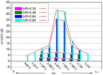
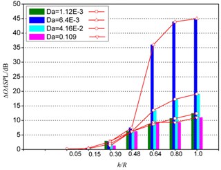
The effect of the permeability and thickness of the porous treatment on the relative overall noise reduction, , (i.e. noise from cylinders with porous treatment relative to the bare cylinder) are presented in Fig. 6. The acoustics measurement point is located at 80 above the cylinder center. The influence of the dimensionless permeability on noise reduction is shown in Fig. 6(a). Results show that in the case of thin porous covers, the level of noise reduction is almost independent of the permeability of the porous material. For cylinders covered with a thick porous coating e.g. 0.64, however, the level of noise reduction can change significantly with varying permeability. The maximum noise reduction can be achieved at 6.4×10⁻³, as also indicated by the previous unsteady force results in Section 3.1. The effect of porous coating thickness on noise reduction is shown in Fig. 6(b). It can be seen that for cases of 0.48, the is quite small, while for cases with 0.48, the porous treatment lead to a sharp increase, especially for critical permeability .
Fig. 6The influence of porous coating a) permeability and b) thickness on ΔOASPL
a)
b)
4. Three-dimensional simulation for understanding the mechanisms
For the three-dimensional simulation, the spanwise length is chozen for better representing the three-dimensional flow features and balancing the computaitonal cost [32]. The properties of porous materials coating are 4.16×10⁻² and 0.80 which are similar to the parameters used by Takeshi et al. [10] in experiment. The three-dimensional vorticity structure is identified by criterion which is expressed by:
where the maximum positive value of corresponds to the vorticity core region and the negative value corresponds to the pure shear flow without vortex motion. Seen from the instantaneous three-dimensional vorticity structures in Fig. 7(a), the shear layer of the rigid cylinder just develops over the rear surface. In addition, it comprises complicate three-dimensional coherent structure and small-scale structure associated to the Kelvin-Helmholtz instability (KHI) [33]. In this case, the near wake disturbance is strong and ‘flaps’ behind the cylinder. More explains of this instability mode can be found in the work of Blevins [33]. Regarding the porous materials coating (PMC) cylinder, the smooth free shear layer over the porous surface detaches from two sides. The stable laminar shear layer develops further downstream and transition to the turbulent vorticity wake. Additionally, the three-dimensionality and KHI of free shear layer are suppressed significantly so that it behaves more synergetic along spanwise direction. The shedding vortex from the core cylinder below porous surface is actually very weak because the dissipation effects of porous materials. The far downstream wake of different cylinders has similar vortex characteristic such as appearance of streanwise vortex, necklace vortex and spanwise vortex. The complex flow structures here were not yet found by the previous two dimensional approaches. So, the three-dimensional study is the important supplement to reveal more information of flow modification by PMC.
To identify the effects of flow control by PMC on vorticity modification at different directions, Fig. 8 presents the contours of vorticity of , and directions respectively, in three columns. The top and bottom row represents the rigid cylinder and PMC cylinder respectively. Generally, the scale of flow structure in PMC case is always larger than that of rigid cylinder which implies possible suppression of small-scale vortex. It is more obvious for the modification of () which means that shear effects on - plane is significantly controlled, just like the previous two-dimensional results shown in Fig. 4 and Fig. 5. Five cut-planes vorticity contours equal-spaced along the spanwise direction are shown in the followed Fig. 9. The left one represents the rigid cylinder and the right one represents the PMC cylinder respectively. It is found that the flow structure of rigid cylinder has remarkable spanwise difference. In contrast, for the PMC cylinder at different planes, it shows similar flow structure. This result provides evidence again of the spanwise synergy effects of PMC on flow structure.
Fig. 7Instantaneous iso-contours with Q-criterion value of 0.8. The colors represent the streamwise velocity value u/U∞
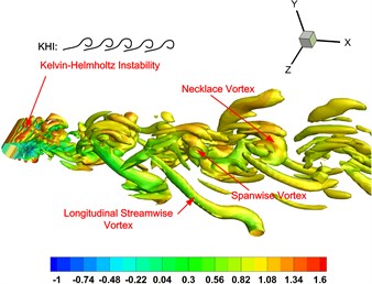
a) Rigid cylinder
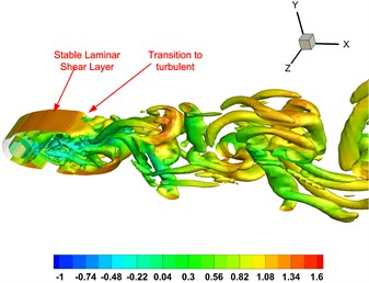
b) PMC cylinder
Fig. 8Instantaneous iso-contours of vorticity magnitude with normalized value of 2: ωxD/U∞, ωyD/U∞ and ωzD/U∞ for rigid cylinder and PMC cylinder respectively
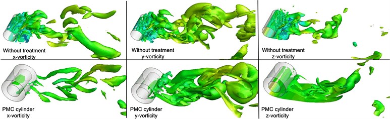
Fig. 9The vorticity structure at various planes along Z direction
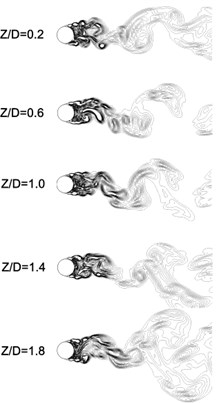
a) Without treatment
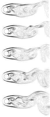
b) PMC cylinder
Fig. 10 shows the time history of lift coefficient and acoustics spectrum. The sound measurement position is above the cylinder center with distance of 80 in the middle plane, computed through three-dimensional LES approach. In Fig. 10(a), the fluctuating magnitude and frequency can be reduced significantly by PMC and become more regular. The fast Fourier transform (FFT) of lift coefficient are also inserted as subplot of the figure which can demonstrate the conclusion from the view of frequency. Fig. 10(b) shows the acoustics spectrum changes caused by PMC. The tonal noise level is reduced by 15 dB. The previous two-dimensional approach over-predicted the noise reduction value around 2 dB which can be attributed to the assumption of fully correlated flow over the spanwise direction of cylinder in the 2D simulation [22]. In Fig. 10(b), the dominant frequency is moved to lower range which is similar to the conclusions of early publication using two-dimensional method [20]. However, through three-dimensional simulation, additionally, it is also found that the tonal bandwidth become narrow for PMC case compared with the rigid case. And the PMC seems to filter the ‘needling’ of sound spectrum, which appears in the results of rigid case. Because the employed method of signal process is identical, it is attributed to the acoustics modulation by flow control. The Kelvin-Helmholtz instability (KHI) produces the additional small-scale vortex that is considered to be the reason for these extra acoustics component (‘needling’). It can be concluded that the PMC can modify not only the large vorticity structure (coherent structure) but also the small vorticity structure (KHI).
Fig. 10Time history of lift and acoustics spectrum at (0, –80D, 0) position
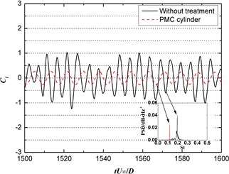
a) Lift coefficient
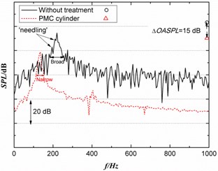
b) Acoustics spectrum
Fig. 11The pressure coefficient contour around cylinder surface in the middle plane of Z direction (dashed line denotes the negative value)
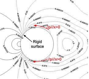
a) Rigid cylinder
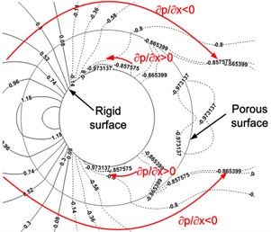
b) PMC cylinder
Until now, it is well known that the vortex shedding can be suppressed by the porous materials coating (PMC) [7, 9, 10, 12-14]. To reveal more essential mechanisms, Fig. 11 presents the pressure field around the cylinder. Adverse pressure gradient () normally appears around the rigid cylinder which is responsible for the boundary layer separation and subsequent vortex shedding. However, for the PMC cylinder, flow around the PMC surface is with favorable pressure gradient () which causes the vortex shedding suppression and flow stability. Even the adverse pressure gradient also appears under the porous surface, but the dissipation attenuates the intensity of shedding from the inside solid cylinder significantly which therefore, has little influences on the whole flow field.
5. Conclusions
Numerical investigations on aerodynamics and acoustic performance of a single circular cylinder treated with porous materials coatings at 4.7×10⁴ has revealed that the permeability plays an important role and can determine the effectiveness of the porous treatment for controlling the vortex shedding, unsteady forces and the far-field noise. The non-dimensional permeability about 6.4×10⁻³ is found to achieve the maximum noise reduction and deviation from this critical value causes the degradation of control ability. Under the critical permeability, the free shear layer is elongated significantly. The porous coating thickness for effective noise reduction is suggested to be larger than 0.3 at least. In addition, the permeability behaves more sensitively under the thicker porous coatings. Three-dimensional simulation reveals that the spanwise modification is more obvious rather than other directions by PMC and the flow structure is more synergetic along spanwise direction. The favorable pressure gradient form around the porous surface is partly the underlying physical mechanisms of vortex shedding suppression.
References
-
Gad-el-Hak M. Flow Control: Passive, Active, and Reactive Flow Management. Cambridge University Press, New York, 2007.
-
Heenan A., Morrison J. Passive control of pressure fluctuations generated by separated flow. AIAA Journal, Vol. 36, Issue 6, 1998, p. 1014-1022.
-
Hahn S., Je J., Choi H. Direct numerical simulation of turbulent channel flow with permeable walls. Journal of Fluid Mechanics, Vol. 450, 2002, p. 259-285.
-
Rashidi S., Bovand M., Valipour M. S. Numerical simulation of forced convective heat transfer past a square diamond-shaped porous cylinder. Transport in Porous Media, Vol. 102, Issue 2, 2014, p. 207-225.
-
Sohankar A., Khodadadi M., Rangraz E. Control of fluid flow and heat transfer around a square cylinder by uniform suction and blowing at low Reynolds numbers. Computers and Fluids, Vol. 109, 2015, p. 155-167.
-
Hu Y., Li D., Shu S., Niu X. Immersed boundary-lattice Boltzmann simulation of natural convection in a square enclosure with a cylinder covered by porous layer. International Journal of Heat and Mass Transfer, Vol. 92, 2016, p. 1166-1170.
-
Bruneau C.-H., Mortazavi I. Passive control of the flow around a square cylinder using porous media. International Journal for Numerical Methods in Fluids, Vol. 46, Issue 4, 2004, p. 415-433.
-
Zhao M., Cheng L. Finite element analysis of flow control using porous media. Ocean Engineering, Vol. 37, 2010, p. 1357-1366.
-
Yu P., Yan Z., Lee T. S., Chen X. B., Low H. T. Steady flow around and through a permeable circular cylinder. Computers and Fluids, Vol. 42, Issue 1, 2011, p. 1-12.
-
Takeshi S., Takehisa T., Mitsuru I., Norio A. Application of porous material to reduce aerodynamic sound from bluff bodies. Fluid Dynamics Research, Vol. 42, Issue 1, 2010, p. 015004.
-
Naito H., Fukagata K. Numerical simulation of flow around a circular cylinder having porous surface. Physics of Fluids, Vol. 24, Issue 11, 2012, p. 117102.
-
Liu H., Wei J., Qu Z. The interaction of porous material coating with the near wake of bluff body. Journal of Fluids Engineering, Vol. 136, Issue 2, 2013, p. 021302-021302.
-
Pinar E., Ozkan G. M., Durhasan T., Aksoy M. M., Akilli H., Sahin B. Flow structure around perforated cylinders in shallow water. Journal of Fluids and Structures, Vol. 55, 2015, p. 52-63.
-
Geyer T. F., Sarradj E. Circular cylinders with soft porous cover for flow noise reduction. Experiments in Fluids, Vol. 57, Issue 3, 2016, p. 1-16.
-
Ali S. A. S., Liu X., Azarpeyvand M. Bluff body flow and noise control using porous media. 22th AIAA/CEAS Aeroacoustics Conference, AIAA Paper 2016-2754, 2016.
-
Liu H., Azarpeyvand M. Passive control of tandem cylinders flow and noise using porous coating. 22th AIAA/CEAS Aeroacoustics Conference, AIAA Paper 2016-2905, 2016.
-
Yamamoto K., Hayama K., Kumada T., Hayashi K. FQUROH: a flight demonstration project for airframe noise reduction technology – concept and current status. 22th AIAA/CEAS Aeroacoustics Conference, AIAA Paper 2016-2709, 2016.
-
Khorrami M. R., Choudhari M. M., Lockhard D. P., Jenkins L. N., McGinley C. B. Unsteady flowfield around tandem cylinders as prototype component interaction in airframe noise. AIAA Journal, Vol. 45, Issue 8, 2007, p. 1930-1941.
-
Casalino D., Jacob M. Prediction of aerodynamic sound from circular rods via spanwise statistical modelling. Journal of Sound and Vibration, Vol. 262, Issue 4, 2003, p. 815-844.
-
Liu H., Azarpeyvand M., Wei J., Qu Z. Tandem cylinder aerodynamic sound control using porous coating. Journal of Sound and Vibration, Vol. 334, 2015, p. 190-201.
-
Revell J., Prydz R., Hays A. Experimental Study of Airframe Noise vs. Drag Relationship for Circular Cylinders. Lockheed Report 28074. Final Report for NASA Contract NAS1-14403, 1977.
-
Cox J. S., Brentner K. S., Rumsey C. L. Computation of vortex shedding and radiated sound for a circular cylinder: subcritical to transcritical Reynolds numbers. Theoretical and Computational Fluid Dynamics, Vol. 12, Issue 4, 1998, p. 233-253.
-
Norberg C. Fluctuating lift on a circular cylinder: review and new measurements. Journal of Fluids and Structures, Vol. 17, Issue 1, 2003, p. 57-96.
-
Orselli R. M., Meneghini J. R., Saltara F. Two and three-dimensional simulation of sound generated by flow around a circular cylinder. 15th AIAA/CEAS Aeroacoustics Conference, AIAA Paper 2009-3270, 2009.
-
Ansys-Fluent 14.0 User’s Manual. Fluent Inc., USA, 2006.
-
Vafai K. Convective flow and heat transfer in variable-porosity media. Journal of Fluid Mechanics, Vol. 147, Issue 1, 1984, p. 233-259.
-
Hsu C., Cheng P. Thermal dispersion in a porous medium. International Journal of Heat and Mass Transfer, Vol. 33, Issue 8, 1990, p. 1587-1597.
-
Ffowcs-Williams J. F., Hawkings D. L. Sound generation by turbulence and surfaces in arbitrary motion. Philosophical Transactions of the Royal Society of London. Series A, Mathematical and Physical Sciences, Vol. 264, 1151, p. 321-342.
-
Brentner K. S. B., Farassat F. An analytical comparison of the acoustic analogy and Kirchhoff formulation for moving surfaces. AIAA Journal, Vol. 36, Issue 8, 1998, p. 1379-1386.
-
Eltaweel A., Wang M., Kim D., Thomas F. O., Kozlov A. V. Numerical investigation of tandem-cylinder noise reduction using plasma-based flow control. Journal of Fluid Mechanics, Vol. 756, 2014, p. 422-451.
-
Lam K., Lin Y. Effects of wavelength and amplitude of a wavy cylinder in cross-flow at low Reynolds numbers. Journal of Fluid Mechanics, Vol. 620, 2009, p. 195-220.
-
Kravchenko A. G., Moin P. Numerical studies of flow over a circular cylinder at Re=3900. Physics of Fluids, Vol. 12, 2000, p. 403.
-
Blevins R. D. Flow-Induced Vibration. New York, Van Nostrand Reinhold Co., 1977.
Cited by
About this article

This work was supported by the National Natural Science Foundation of China (Grant No. 51506179) and the Fundamental Research Funds for the Central Universities (Grant No. 3102016ZY018). The helpful discussion with Dr. Mahdi Azarpeyvand of University of Bristol is greatly acknowledged.
