Abstract
Experiments of flow-induced vibrations using a closely-packed triangular rods array with a pitch-to-diameter ratio of 1.1 in water cross-flow were carried out to analyse the detected effects of system parameters in the frequency domain and vibration amplitudes. Single flexibly mounted rod with two degrees of freedom at each end of it was located in the second or the fourth row in the bundle with 21 row. Influence of increasing/decreasing flow, the test rod mass and support stiffness changes were analysed. Reynolds number based on the freestream velocity and a rod diameter was up to 1.64·104. Accelerometers and laser sensors were used to measure the time-varying response of the test rod. FFT approach was adopted to reconstruct the displacements from accelerometer measurements. Experimental results show that the behaviour of the flexibly-mounted rod is dependent on the flow time-history. Dominant flow-dependent and flow-independent frequencies were observed in the frequency domain. Changes in the frequency spectrum introduced by the test rod mass and support stiffness were identified. Oscillation regime of the test rod when the state equilibrium position becomes unstable with the limited oscillations was detected. Metamodeling approach was applied to develop mathematical approximation using three parameters: flow rate, stiffness coefficient and frequency ratio. Good accordance has been found between the inverse model and laboratory experiments.
Highlights
- The parameters of the single flexibly-mounted rod were studied in a rigid rod bundle in increasing / decreasing crossflow.
- The influence of system parameters on the rod dominant frequencies was obtained.
- The inverse approximation model was developed to predict the support changes of a flexibly-mounted rod.
1. Introduction
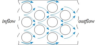
In engineering, vibration analysis is commonly used for structural health monitoring. Oscillations induced by the fluid flow may be a reason for serious fatigue failures. Vibrations induced by the crossflow (flow is perpendicular to the rod axis) are responsible for the vast majority of failures in the multi-tube systems [1], see Fig. 1. These problems are especially acute in nuclear plants where repairs of tubes could be costly. Therefore, mechanisms of early diagnostics of the system malfunctions related to the flow-induced vibration would be helpful. Given the complexity of the system, it is not possible to monitor individual elements of the system. One possibility would be to analyse system frequencies in the case if in the frequency spectra can detect changes in the system parameters.
A significant amount of studies (experimental and numerical) has been conducted to understand the physics of the phenomenon attributed to crossflow-induced vibration. Already in the early researches were founded three leading causes of vibration of the structural element in a liquid flow: vortex shedding, turbulent buffeting and fluidelastic excitation. For example, Žukauskas and Katinas [2] report results on frequencies of the vortex shedding in staggered and in-line bundles of different pitches. Flows of liquid and gases were studied. Nagamatsu and Rolsma [3] investigated row depth effects on vortex shedding and turbulent buffeting formation. Owen [4] reported about vibration associated with randomly fluctuating forces imposed on the tubes by the turbulent eddies. In the case of liquid as surrounding substance, Weaver and Grover [5, 6] experimentally found three mentioned excitation mechanisms in a tubes bank with 19 flexibly mounted tubes surrounded by 116 rigid ones.
Fig. 1Cross-flow through the bundle of cylindrical tubes
Although the flow-induced vibrations in rods bundles have been studied for several last decades, it is still a topical area of research because such systems have a lot of variables. Liu et al. [7] examined the tightly-packed rigid tube bundle. An instrumented test bundle was constructed to measure fluid excitation forces (from vortex shedding and turbulence) acting on cylinders in the normal triangular tube array ( 1.28) with water cross-flow. From the research follows that the rod position is critical regarding excitation forces acting in the bundle. Lin and Yu [8] did experiments to investigate the influence of surrounding cylinders on a critical velocity and a vibration amplitude and orbits of the central cylinder. Results of the cross-flow induced vibrations of a cylinder showed that initially, the central cylinder vibrates only at its natural frequency around the onset of fluidelastic instability. Increasing the water velocity, the vibration frequency also includes components of the surrounding cylinders.
Lai et al. [9] investigated the mechanism of cross-flow effects on fluidelastic instability of tube bundles. Authors found that if system damping is small, two critical states can be observed regarding the stability of tube array. Andjelić et al. [10] founded the multiple stability boundaries of the flexibly-mounted tube in a fixed array. A crucial effect of structural damping and the strong dependency of the array geometry on the tube vibration were detected. Fluidelastic instability in the streamwise (inflow) direction in the air-flow at several patterns of triangular cylinder arrays is reported by Nakamura et al. [11]. As mentioned in the paper, fluidelatic instability caused by the cross-flow was found to occur in air-flow easily than in water-flow. Meskell and Fitzpatrick [12] found that nonlinearity between fluid force and the tube motion is more significant in closely packed arrays. They used normal triangular tube array tests with a single flexible tube. Turbulence influence on the tube response has been investigated in [13, 14]. Rottmann and Popp [13] found the stabilising effect of upstream turbulence in parallel triangular tubes bundle ( 1.375) in air-flow. However, it should be considered that additional turbulence at the inflow could increase the buffeting amplitudes. As conclude Taylor and Pettigrew [14], high upstream turbulence can significantly increase tube vibrations but only in the first few rows of the bundle. After the fifth row, the response is similar to that caused by uniform flow.
When the flexible tube is described as a cantilever beam, for example, in [15], the full spectrum of eigenfrequencies emerges even for the dry system. Contrary, in the present study, the weak elastic element is introduced, so only a few natural frequencies of oscillation were expected. Rigid-body like motion with two degrees-of-freedom is achieved using two elastic beams at both ends of the test rod, similar to in [16, 17]. Such a system is chosen as a model system for vibration analysis of an individual beam in SINQ target.
Swiss Spallation Neutron Source (SINQ) is a proton beam target located in Paul Scherrer Institute (Switzerland). The key element of the target is a bundle of rods (315 pieces in 37 rows) fabricated from Zr-alloy tubes and filled with Pb. Due to the way of mounting of the cylindric rods in the target, see Fig. 2(a), it is expected that the rod can move within a small tolerance range in the plane perpendicular to the axis of the cylinder. A proton beam initiates a spallation reaction, which is accompanied by a powerful heat release in the rods. The rods are cooled by turbulent heavy water cross-flow that can induce the vibrations of the rod. Parameters of the vibrations depend on the structure rigidity, geometry of the flow path, heavy water properties and flow rate. The SINQ target is well designed, but the total power has tremendously increased over the years. Therefore, in specific cases, it is possible that in the rod occurs damages because of water boiling, crack of the pipe and lead leakage etc., see Fig. 2(b). Any change in the target parameters should be visible as a change in vibration frequency or amplitude. That would allow using the analysis of detected frequencies as one of the mechanisms for the structural health monitoring of the target.
Fig. 2a) Mounting of Pb filled rods in the SINQ proton beam target; b) photographs of a rod after an operation in SINQ targets with damage which leads to mass reduction due to lead leakage [18]
![a) Mounting of Pb filled rods in the SINQ proton beam target; b) photographs of a rod after an operation in SINQ targets with damage which leads to mass reduction due to lead leakage [18]](https://static-01.extrica.com/articles/20596/20596-img2.jpg)
a)
![a) Mounting of Pb filled rods in the SINQ proton beam target; b) photographs of a rod after an operation in SINQ targets with damage which leads to mass reduction due to lead leakage [18]](https://static-01.extrica.com/articles/20596/20596-img3.jpg)
b)
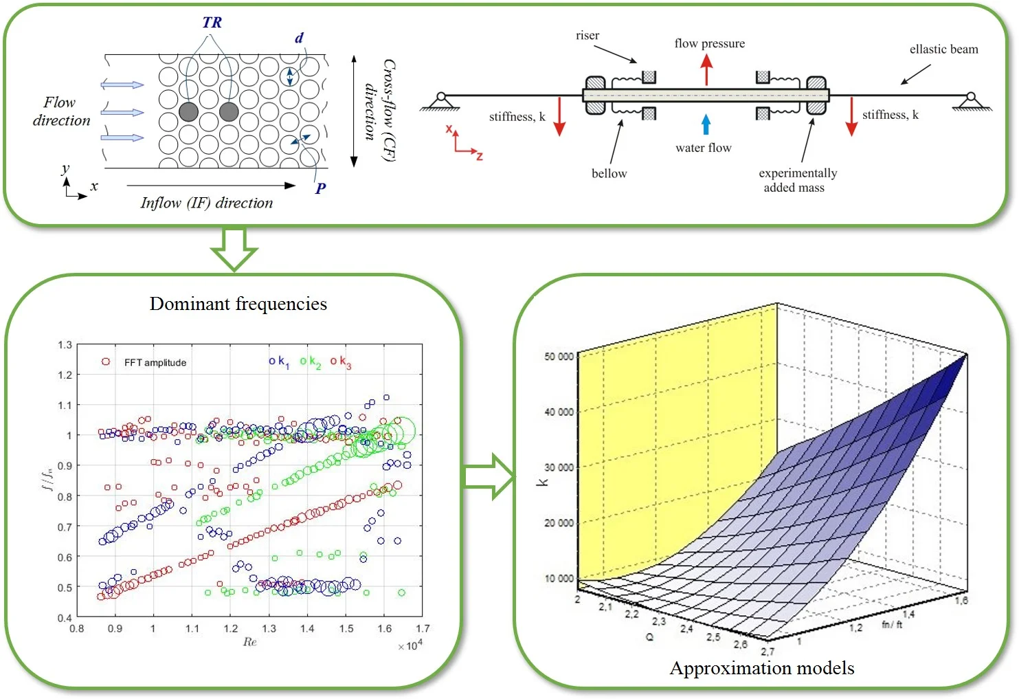
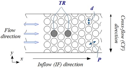
To analyse the effect of system parameters on the measured amplitudes and frequencies the mock-up of SINQ target has been used. The model system contains a single flexibly-mounted test rod (TR) in an otherwise fixed rods array of triangular arrangement with a pitch-to-diameter ratio of 1.1. The TR is excited by the single-phase cross-flow. The response frequencies and amplitudes in the inflow (IF) and cross-flow (CF) direction were obtained under both increasing and decreasing flow velocities. The influence of the oscillating mass on detected frequencies has been analysed experimentally adding mass elements to the TR. The effect of the supporting stiffness on oscillation amplitudes and dominant frequencies of the TR was studied. The impact of the TR position in the array was analysed as well.
In order to predict the typical behaviour of the system by using a low-dimensional representation for a high-dimensional problem, a mathematical approximation was applied. In the last years, model reduction methods are becoming more and more topical in flow-induced vibration research and analysis, for example, [19, 20]. Response Surface Method is used to build approximation models in this study. The direct model contains two inputs: flow rate and elastic beam stiffness coefficient , and one response – frequency ratio . The inverse model was build using flow rate and frequency ratio , as inputs and the stiffness coefficient as a response.
2. Experimental facility and instrumentation
To study the flow-induced vibration in a closely-packed rods array, a closed-circuit water channel with a triangular rods bundle was developed at Paul Scherrer Institute (PSI). The experimental system consists of a water loop, a test section with a rods array and single flexibly-mounted test rod (TR) in it, measurement sensors, and a data acquisition system.
2.1. Installation and rods array
The test segment with the rods bundle consists of a rectangular channel of cross-section 30×97 mm2 sharply passing into cross-section 30×47 mm2. The rods array with 21 row of rigid, circular cylindrical stainless steel rods with diameter 8 mm is placed in the narrow part of the channel, 97 mm from the inlet of the section. As shown in Fig. 3, the rods are arranged in a triangular array with a small pitch-to-diameter ratio (1.1). The array rows contain 5 rods in each including the half rods at each second row which were installed along the wall. The rods are rigidly fixed in hollows in the plexiglass cover. It is expected that its natural frequency is much higher than the TR frequency. All rods are identical, 30 mm long and of the same mechanical properties.
Fig. 3Cross-section of the rods bundle with a single flexibly-mounted cylinder (TR) in the 2nd or the 4th row; the cylinder diameter, d, the pitch, P
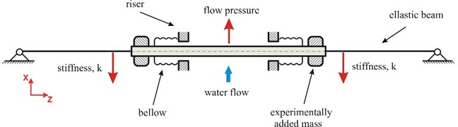
The experimental study of Weaver and El-Kashlan [21] shows that the critical rows for instability in a triangular array of tubes are the third and fourth one. Based on it, the major investigation was performed when the TR is located in the middle of the fourth row. The position was changed to 2nd row removing the first two rows to investigate the effect of the TR position and the bundle deep on the response of the rod in a cross-flow. The TR ends (denoted as “End I” and “End II”) are clamped in bellows which provide waterproofing. The free movement of the TR in CF and IF directions is allowed by two elastic cylindrical beams (128 mm long), see the sketch in Fig. 4. The elastic constraint is linear. Three kinds of elastic beams with different diameters were explored. In this paper, the elastic beams are characterized by its stiffness, . The mass of the elastic beam is much smaller than the rod (less than 3 % of the TR mass).
Fig. 4A sketch of the TR mounting
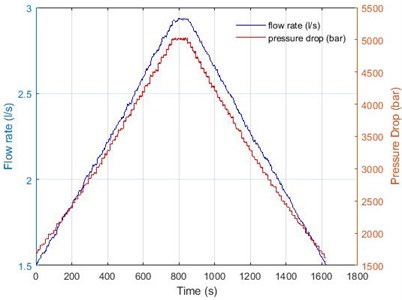
The water loop system is formed by rectangular inlet and outlet (both 30×47 mm2) water channels, an expansion tank, a water pump, a flow-meter, a manometer, and the rods bundle described above. The flow rate adjusts the velocity of water in the channel. The range of the flow rate was from 0.3 to 2.9-3.0 l/s. The Reynolds number based on the inlet velocity and cylinder diameter is until 16.4·103 (, where is the kinematic viscosity of water). The flow velocity is changed stepwise. The typical time history of the flow rate and a pressure drop is shown in Fig. 5. The maximum velocity starting from the minimum value is achieved in 100 steps. It is changed flow velocity from the maximum to the minimum in the same way. The reduced velocity, is introduced as:
where is the inlet velocity of the test segment, is the natural frequency of the oscillating part in water flow.
Fig. 5Typical time history of the flow rate and a pressure drop during the experiment
2.2. Instrumentation and data acquisition
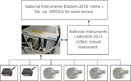
Non-contact measurement methods have been used to obtain data of the TR responses depending on different input parameters. The instrumentation includes four single-axis accelerometers and two laser triangulation sensors. The maximum measurement sampling frequency is 2 kHz for both accelerometer and displacement sensors.
Kistler’s 8640A5 accelerometers with acceleration range ±5 g, sensitivity 1000 mV/g, the frequency response of 0.5-3000 Hz, and voltage full-scale ±5 V are used for acceleration measurements. Two single-axis accelerometers are installed on both sides of the water channel at the ends of the TR. Measurements of acceleration in both CF (-axis) and IF (-axis) directions have been obtained.
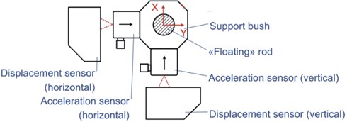
optoNCDT 1320 laser triangulation sensor with measuring range 10 mm, measuring rate 2 kHz, and 10 µm reproducibility is used to measure displacements of the flexibly-mounted TR directly. Two laser sensors are installed on the TR “End I”. Each of the sensors is sensitive to TR vibrations only in one (IF or CF) direction. The sketch of the sensors at the “End I” of the TR can be seen in Fig. 6.
Fig. 6A sketch of the instrumentation of the TR
Random features are observed in virtually all measurements [22]. Therefore, the standard deviation, of sensors measurements at maximum flow rate has been calculated to estimate the random error. Average standard deviations and standard errors () of four experiments of the “End I” response are summarised in Table 1.
Table 1Standard deviation and error of measurements of accelerometers and laser sensors
Accelerometer 1 (CF) | Accelerometer 2 (IF) | Laser 1 (IF) | Laser 2 (CF) | |
0.1984 | 0.2014 | 0.0089 | 0.0079 | |
0.0992 | 0.1007 | 0.0047 | 0.0037 |
From Table 1 follows that accelerometer measurements are more dissipated. Therefore, laser sensors have a smaller standard error comparing to accelerometers. The acquisition system of measurements data is presented in Fig. 7. Measured data from six sensors are stored in “tdms” files. In addition to acceleration and displacement measurements, the flow rate, pressure drop, and temperature are also stored.
Fig. 7A scheme of the measurements data acquisition system with two laser sensors and four accelerometers
2.3. Coordinate system
The Cartesian coordinate system is defined such that the -axis points in the direction of the flow (IF), the -axis in the perpendicular direction (CF) and the -axis is the axis of the rod. The origin of the coordinate system is in the centre of the TR at the non-flow regime.
3. Experimental data post-processing
The responses of the TR using data from accelerometers are reconstructed by employing the fast Fourier transform (FFT) and the inverse Fourier transform. The following algorithm is used to obtain velocity and a displacement from the accelerometer time history:
where is measured acceleration, , and is a frequency of oscillations. The filter is applied to remove the cut-off frequency to destroy the low-frequency effects lower than 2 Hz. Validation of the applied algorithm is done using measurements from laser sensors.
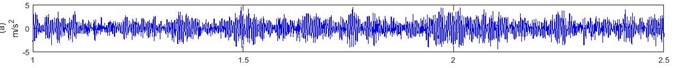
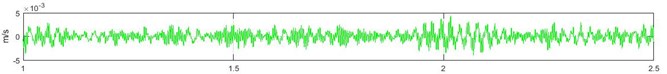
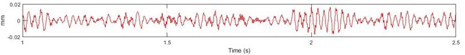
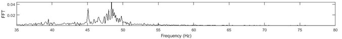
An example of measured and reconstructed signals and a frequency spectrum of the displacement is given in Fig. 8. The first row shows the time history of measured acceleration, the second row presents reconstructed TR velocity in CF direction, and the third row illustrates the time-varying displacements of the TR perpendicular to the flow. From Fig. 8(b) follows that the TR velocity is much smaller than the inflow water velocity. The fourth row presents the frequency spectra of the displacement in CF direction where the peak value at 48.1 Hz corresponds to the TR natural frequency in the water flow and frequency at 45.1 Hz is related to turbulent fluctuations in the flow.
Fig. 8An example of reconstructed values using Fourier transform approach. a) time history of measured acceleration signal in CF direction (m/s2); b) reconstructed velocity (m/s); c) reconstructed displacement (mm); d) frequency spectra of the displacement in CF direction (Hz)
a)
b)
c)
d)
4. Experimental results and discussion
The analysis of the TR behaviour is based on oscillation amplitudes in CF and IF directions as well on oscillation frequencies in both directions. Since both accelerometer and laser sensor data are available, it is possible to divide the total TR displacement into two parts: permanent deflection () from the origin of the coordinate system and averaged amplitude of fluctuations ().
The can find directly from the laser sensor measurements using averaged value. Although the laser data are available only at “End I”, it is assumed that on average, the permanent deflection in CF and IF direction is the same for both sides of the TR. Accelerometer measurements give fluctuating part of displacements, .
4.1. Feasibility study
Three experiments before parametric studies were done to provide better insights into the vibration characteristics of the analysed model system. The experimental session was started with measurements without flow. All frequencies detected in this case are defined as environmental noise. Typically, a distribution of the noise measured by accelerometers is similar to Gauss distribution. Sensor measurements show that the analysed system has a significant level of environmental noise.
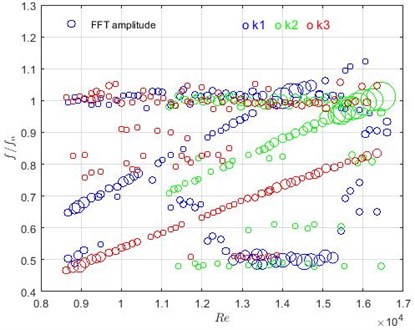
Measurements with all fixed rods in the flow allow identifying frequencies which are related to the flow characteristics or the system but not with vibrations of the TR. The detected dominant frequencies versus Reynolds number are presented in Fig. 9. The radius of the circle illustrates the amplitude of FFT.
Detected normalized frequencies around 33 Hz were observed in the case without flow as well, therefore, it is assumed that these frequencies are related to the environmental noise. In addition, they are not dependent on other changes in the initial conditions, therefore, they are not taken into account for the future analysis. There are a set of frequencies which are strongly related to the flow velocity, higher frequency corresponds to the faster water flow. The relationship between the frequency and water velocity is linear. The assumption that periodic excitation mechanism causes this can be made following the power spectral density (PSD) graphs (see Fig. 10) where a narrow band peak is indicated. PSD, where the power normalises by the frequency resolution, is calculated as:
where is a sampling frequency, and is a number of samples.
Fig. 9Dominant frequencies in the case when all rods are fixed. FFT amplitude is illustrated by the radius of green circles
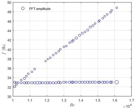
Fig. 10Typical spectra of PSD with a peak value at 46.1 Hz. On the horizontal axis is the frequency in Hz and on the vertical axis is power/frequency in dB/Hz
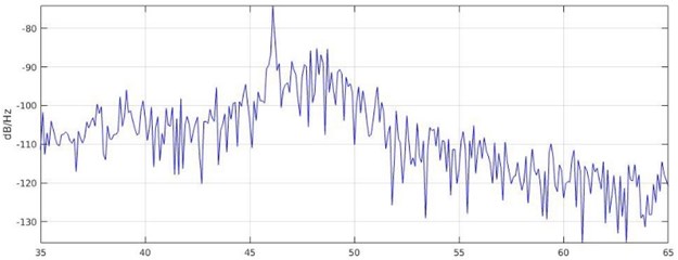
As mentioned Źukauskas and Katinas [2], the primary cause of the fluctuating fluid force on the tubes is a periodic variation of circumferential pressure distribution which is observed in any cross-flow. Usually, the periodic phenomenon in a bundle is referred to as vortex shedding that occurs at a constant Strouhal number, or the considering turbulent buffeting. Ziada [23] did air tests to investigate vorticity shedding excitation in normal triangular tube array with a different pitch ratio. He divides two periodic frequency components: 1) the highest corresponds to the vortex shedding observed mainly behind the front rows and 2) the lower component has the characteristics of turbulent buffeting excitation for small tube spacing. Several different typical ranges of a frequency described by constant values of has been reported in other papers as well, for example, Žukauskas and Katinas [2], Weaver and Fitzpatrick [24]. Experiments also suggest that only one Strouhal number is found after the fourth row.
As follows from the researches of other authors ([2, 25]), value increases with a reduction of the relative pitches. For the leading row with transverse pitch-to-diameter ratio 1.2, analytical expression gives of 0.57 or 0.73 depending on the author. In staggered bundles, the is related to both transversal and longitudinal pitches. is dependent as well from Reynolds number, level and scale of turbulence, damping rate and position of the tube inside the bundle and as mentioned Nagamatsu and Rolsma [3] from rows deep of the tubes bank. Inside array frequency of vortex shedding is significantly smaller than of front rows whereas the turbulent energy is increased at each row of tubes [4]. That leads to the turbulent buffeting generates a much stronger excitation force than vortex shedding [3]. In the analysed system with all fixed rods, detected flow dependent frequencies is similar to 0.19. It could be speculated that observed group of frequencies linearly dependent on the flow velocity is related to turbulent fluctuations in the flow.
The damping ratio, of the TR is obtained by using the hammer test and logarithmic decrement () technique:
where is the integer of successive, positive peaks, is the amplitude at time and denotes the oscillation period. The impulse force at both ends of the TR is used as excitation in the hammer test. Obtained results show that 0.020 and 0.019 with standard deviation of 0.003 and 0.002 respectively.
The average value from several measurements is used to estimate uncertainty by evaluating the standard deviation [26]. The uncertainties of the experimental parameters are summarized in Table 2.
Table 2Uncertainties of natural frequencies in the water flow and damping factor
Uncertainty | |
41.9 Hz ± 1.7 | |
48.1 Hz ± 0.98 | |
58.5 Hz ± 3.1 | |
0.020 ± 0.006 | |
0.019 ± 0.004 |
4.2. Increasing – decreasing flow
The increasing flow can be divided into three regions according to the characteristics of the TR vibration amplitudes at the analysed range of velocity:
– vibrations in the first velocity range are with relatively small amplitude;
– in the second region, amplitudes of the TR rapidly increase and after achieving the peak value rapidly decrease;
– in the last velocity range, the behaviour of vibrations becomes similar to the first region.
First two regions can see in Fig. 11(a) and Fig. 11(b) where average dimensionless fluctuating amplitudes, and reconstructed from accelerometer measurements are shown. Comparing experimentally obtained results with data available in the literature (see Fig. 11(c)) allows concluding that in this experiment is analysed region before fluidelastic instability. The peak value at 5 agrees to the reduced velocity where two dominant frequencies overlap, see the next subsection.
Fig. 11The average non-dimensional fluctuating amplitude of the TR in a) IF and b) CF direction versus reduced velocity; c) excitation mechanisms in the tube bundle depending on the flow velocity [27]
![The average non-dimensional fluctuating amplitude of the TR in a) IF and b) CF direction versus reduced velocity; c) excitation mechanisms in the tube bundle depending on the flow velocity [27]](https://static-01.extrica.com/articles/20596/20596-img15.jpg)
On average, values of in IF and CF directions are comparable for increasing flow. The peak value of the normalised amplitude is reached around 5 in both directions. For decreasing flow, the peaks of dimensionless fluctuating amplitude occur at smaller reduced velocities than for growing flow. The maximum values of in both oscillation directions are achieved when the flow increase.
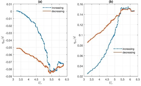
The curve of the permanent displacement of increasing flow differentiates from the curve of decreasing flow. Non-dimensional permanent displacements and of the TR versus reduced velocity are given in Fig. 12. From Fig. 12 follows that the hysteresis effect is observed.
Fig. 12Permanent displacement of the TR in a) CF and b) IF direction versus reduced velocity at increasing and decreasing flow
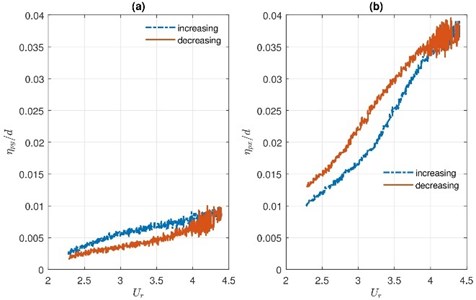
The measurements of permanent displacements show the zero-point shift in the IF direction increase with increasing flow velocity as it was expected. Permanent displacement also is observable in CF direction. Since bundle arrangement is symmetric, a deviation from the origin in CF direction could explain with an initial inaccuracy of the TR position. CF permanent displacement is growing if the flow velocity is increasing. Therefore from Fig. 12(a) can conclude that flow velocity can intensify the effects of the initial inaccuracy of the rod position. The maximum value of is approximately four times smaller comparing to the maximum.
4.3. Effect of the flexibly-mounted rod mass
The influence of the mass of the oscillating part on dominant frequencies has been analysed experimentally adding two mass elements at both sides of the TR, see Fig. 4. The non-dimensional parameter – the mass ratio is introduced:
where is a density of the TR. Two cases with 0.42 and 0.567 are analysed. Dominant, normalised frequencies versus Reynolds number is given in Fig. 13. Blue and red circles correspond to 0.42 and 0.567, respectively.
Fig. 13Dominant, normalised frequencies versus Reynolds number with two mass ratios of the oscillating part. Blue circles correspond to m*= 0.42, red – to m*= 0.567
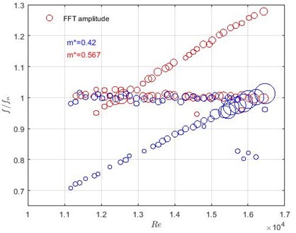
The interaction between the natural frequency of the TR in the water flow and flow-dependent frequencies can be well detected in the case when 0.42. The maximum FFT amplitudes are observable between 5 and 5.5. This range corresponds to the region where the maximum fluctuating amplitudes are detected, see Fig. 11. The FFT amplitudes decrease in the case when the mass ratio is larger. The effect of oscillating mass is observable in frequencies linearly dependent on the flow velocity as well.
Results show that there were detect changes in the TR mass in the frequency domain and it can be useful for structural health monitoring in a case when the rod damages lead to the mass reduction. The future investigations are needed to find the minimum detectable mass change of the oscillating part in the frequency domain.
4.4. Influence of the stiffness of the elastic beams
Changes of the TR support are modelled using three types of elastic beams with stiffness (weak), (medium) and (stiffer) with a diameter of the beam 0.3125 , 0.375 and 0.5, respectively. Locations of the elastic beams in the system can be seen in Fig. 4.
The averaged non-dimensional amplitudes and versus depending on the beam stiffness are presented in Fig. 14.
From Fig. 14 follows in the case with the stiffness (the stiffer beam), the amplitude in CF direction starts to increase when 3.5. In IL direction the influence of increased flow velocity on amplitudes is negligible in the analysed velocity range.
The maximum values of the fluctuating amplitude in both directions are reached when is used beams with medium stiffness . The probability function Eq. (11) is introduced to better understand the behaviour of the TR at the peak values. The probability function, finds areas in the cross-section plane where the end of the TR is the most common at the time:
where is a number of samples in given subarea , is the number of total samples. At both TR ends, the part of the - plane of interest is uniformly divided into small squares. For each of these sub-areas, is calculated. Sketch of the plane splitting is illustrated in Fig. 15.
Fig. 14Averaged fluctuating amplitudes at different stiffness of elastic beams in a) CF direction and b) in IF direction
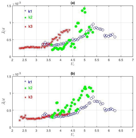
Fig. 15The x-y plane splitting sketch for both TR ends for calculating probability function Pi
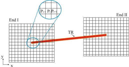
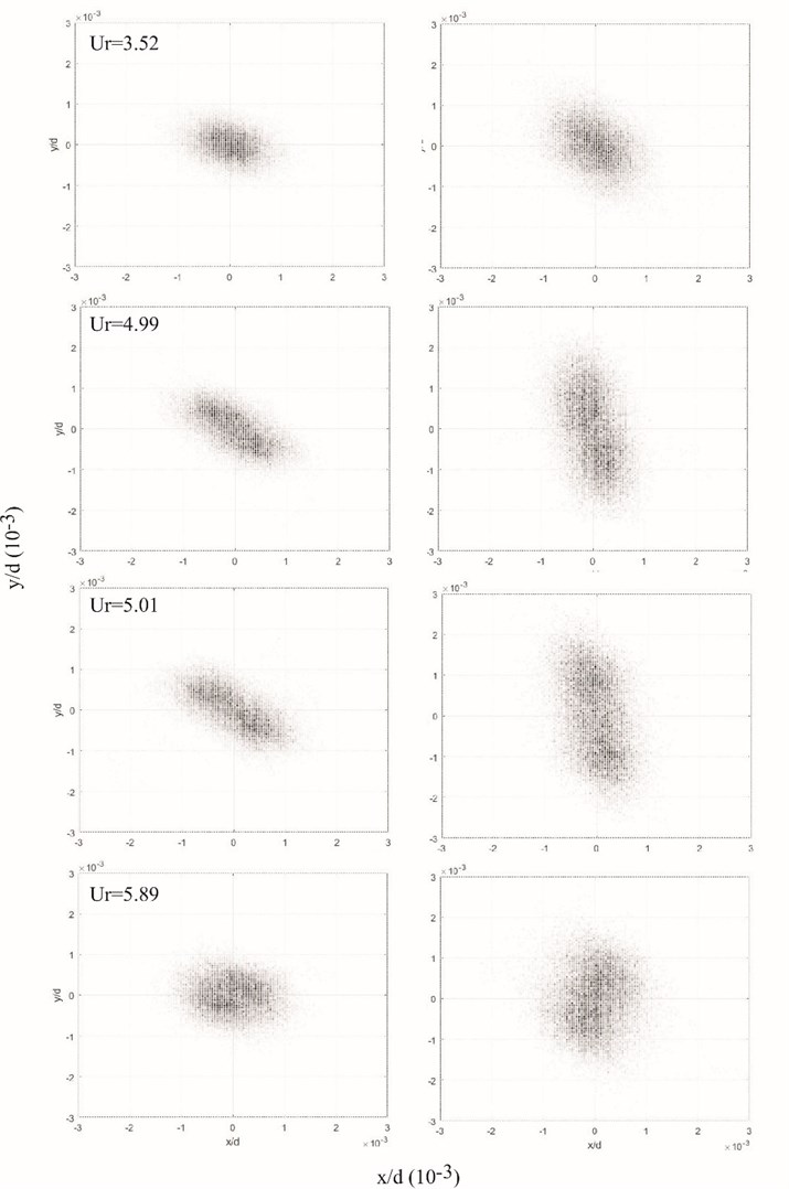
Fig. 16 presents values of the probability function in the - plane of both TR ends at different with 0.42. The reduced velocity is chosen to include the region where frequencies and are overlapping. For clarity, only the dynamics of the “steady state” are illustrated.
Two movement regimes of the TR ends can be detected using the probability approach, see in Fig. 16. When is smaller than ≈ 4.5 or larger than ≈ 5.1, i.e., when frequencies not overlap, TR ends the most time spend around the point which corresponds to the appropriate . Small amplitudes, stochastic oscillations have been observed. An assumed reason for vibrations is turbulent components due to the flow separation from upstream tubes [11]. In the interval where and have similar values, can observed two equilibrium points, see graphs for 4.99 and 5.01. At this range, the stable equilibrium position becomes unstable with a limited cycle of oscillation. Furthermore, the probability maps are not equal for both TR ends.
Fig. 16The probability of a) “End I” and b) “End II” position in the x-y plane at the time for different Ur
In the case when weak elastic beams with stiffness are used, the fluctuating amplitudes increase till 5.3 after that averaged amplitudes decrease. Data of laser sensors shows that at 5.4 the contact problem occurs, i.e., the TR starts to interact with the riser, see Fig. 17. In this paper, processes related to the contact problem are not analysed.
Fig. 17Permanent displacement in a) CF and b) IF direction when elastic beams with stiffness k1 are used
The kinetic energy ratio of the translational and rotational motion (Eq. (12)) of the TR is obtained to investigate the significance of the 3D effects. In the case when stiffness is or , comparison of the kinetic energies shows that the rotational kinetic energy is four to five times larger than the translational kinetic energy when dominant frequencies overlapping. For example in Fig. 13, the rotation movement corresponds to the normalized frequencies near 0.8 for the case of 0.42. From that follows, the water flow induces 3D oscillations of the TR, and therefore 2D numerical models could be not accurate enough to modelling behaviour of similar scenarios.
where the vectors of generalised coordinate correspond to the TR midpoint nondimensional coordinates in IF and CF directions; are vectors of rotation angles of the TR around its midpoint in both directions, is the moment of inertia, and is a distance from the TR midpoint to the mass element.
Fig. 18Dominant normalised frequencies in CF direction with different stiffness of elastic beams
Dominant frequencies for three stiffness of elastic beams are presented in Fig. 18. Similar phase portraits are obtained when stiffness is and . Small changes in the slope of the flow-dependent frequencies groups are observed depending on the stiffness of elastic beams. When stiffness is two bifurcation points can be observed. The bifurcation at 5.5 corresponds to the velocity at which the contact problem occurs.
4.5. Effect of the test rod position and the bundle deep
The impact of the TR location in the rods bundle and the number of rows in the array on the rod behaviour was studied changing the TR position from the 4th row to the 2nd one removing the first two rows of rods, see in Fig. 2. Results show there is no influence on averaged amplitudes in the case when stiffer elastic beams () are used. In cases with medium and more compliant stiffness, the changes in averaged amplitudes of the TR can be observed. The comparison of normalised amplitudes in the 2nd and the 4th row are shown in Fig. 19.
Fig. 19Averaged amplitudes in CF with the stiffness of elastic beams a) k1 and b) k2 depending on the TR position in the bundle
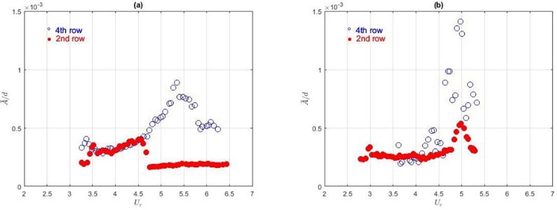
From Fig. 19(a) follows that the average amplitude of the TR grows till 4.5, but after that, the oscillations rapidly decrease when the TR is in the 2nd row and the elastic beam with stiffness is used. In the case with a medium stiffness (), see Fig. 19(b), the peak is reached at the same in both cases only the maximum value is approximately three times smaller when the TR is in the 2nd row. Therefore, can conclude that in analysed cases, the bundle intensify the amplitude of vibrations.
The comparison of detected dominant frequencies in the 2nd and the 4th row shown similar phase portraits for all kinds of the elastic beams.
4.6. Mathematical approximation
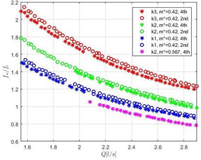
The analysis of obtained experimental results shows that the ratio between and is a response which is dependent on all investigated parameters: the TR mass, support stiffness and the TR position in the bundle and the number of rods in the array. Therefore, the ratio was introduced as the most promising to monitor the system. In Fig. 20 is represented the frequency ratio versus the flow rate .
From Fig. 20 follows that is increasing if stiffness of the elastic beam is increasing. The frequency ratio decreases if the mass of the oscillating part increase. The changes in the number of rows in the bundle and the position of the TR also are detectable using the ratio between flow-dependent and natural frequencies.
To find the approximated input-output patterns, the direct and the inverse models were created. The direct model contains two inputs (factors): flow rate and elastic beam stiffness coefficient . As an output (response) was chosen frequency ratio . The sampling points selection used a Central Composite Design (CCD), which is a classic approach to physical experiments [28]. A modified CCD design with a triple midpoint was created. A second-order regression model was used for approximation, which gives relative cross-validation error Eq. (13) of 8.41 % for the frequency ratio . for the response is 0.998:
where is expected approximation without taking into account the sampling point (1, 2,…, ), is a mean value and is a number of points [29].
Fig. 20Frequency ratio depending on the flow rate at different stiffness k, rod mass m and TR location in the array (in the 2nd or the 4th row)
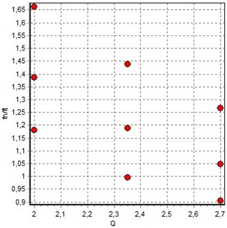
The inverse model had two inputs: flow rate and frequency ratio . The stiffness coefficient was used as a response. The design of the experiment for the inverse model is shown in Fig. 21. The second-order regression model was used as an approximation with a cross-validation error of 3.78 % and 0.999.
Fig. 21Experimental points for the inverse model of two factors
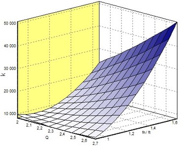
The inverse model equation for the stiffness coefficient of the elastic beam is defined as:
In Fig. 22 is shown the approximation model of the stiffness coefficient as a function of the flow rate and frequency ratio obtained by EDAOpt software [30].
Fig. 22The model of the stiffness coefficient versus design parameters Q and fn/ft
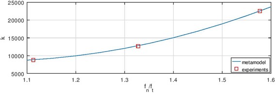
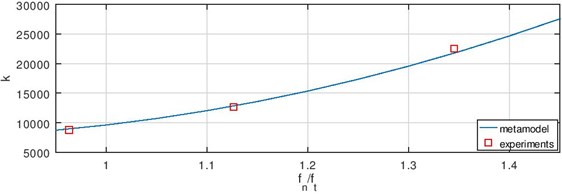
The validation of the inverse model was realised choosing two constant flow rates and comparing model results with values of the laboratory experiments at these flow rates. Graphs of the stiffness coefficient as a function of frequency ration using approximation model Eq. (16) and data from experiments when the flow rate is 2.1 l/s and 2.5 l/s are shown in Fig. 23. One can see that the maximum difference between experimental and approximation model values is less than 3.4 %.
Fig. 23Validation of the model if Q is a) 2.1 l/s and b) 2.5 l/s
a)
The analysis carried out shows that the developed method of approximation and the obtained factors-response relationship has a good fit with the laboratory experiments and therefore it could be useful in the monitoring of multi-rods systems as well as in the design process of such systems.
5. Conclusions
Flow-induced vibration experiments of the single flexibly-mounted rod in otherwise rigid rods bundle were carried out to study the TR motion depending on increasing/decreasing surrounding water crossflow, mass and support stiffness changes of the TR and position in the rods bundle of the TR. Based on the analysis of experimental results of time history, dominant frequencies and amplitude responses, several main conclusions can be achieved.
1) In the analysed range of the increasing flow velocities can define three intervals according to the oscillation amplitudes: (a) small fluctuations when the dominant reason for oscillations is turbulence in the first range; (b) rapid increasing and decreasing of the averaged amplitudes in the second region and (c) small fluctuations of the averaged amplitudes in the third interval. Therefore, based on literature can be concluded that in the experiment is observed two vibration excitation mechanisms – turbulent buffeting and vortex shedding.
2) The curve of measured permanent displacements of the TR is different for increasing and decreasing flows. The maximum averaged amplitude is 0.145 % of the TR diameter when medium support stiffness is used. The maximum is reached with increasing flow regime in both IF and CF directions. Reduced velocity at which peak values of averaged TR oscillation amplitude occurs is different for increasing and decreasing flows. Therefore, can conclude that the hysteresis effect is observed.
3) Dominant flow-dependent and flow-independent frequencies have been detected in the frequency domain. Frequency independent of the flow velocity corresponds to the natural frequency of the TR. Frequency linearly-dependent on the flow velocity could be related to the periodic flow fluctuations.
4) In some cases, the failure of rods in the bundle can be related to the mass changes of the rod. Experimental results show that the mass ratio reduction of 35 % is well detectable in a frequency spectrum. The effect of the TR support is analysed changing the stiffness of elastic beams. The stiffness influence can be detected in both the frequency domain and averaged amplitudes.
5) Probability function which describes the plane area where ends of the TR are the most common at the time is introduced. Analysis of probability graphs shown the TR oscillation regime when the state equilibrium position becomes unstable with the limited oscillations. It occurs when the natural and flow-dependent frequencies overlap. Comparing probability graphs of both ends of the TR it is found that movements of TR ends are different in this interval. The 3D movement has been detected using kinetic energy ratio of the TR midpoint motion and rotational movement of the TR.
6) In the frequency spectra of frequency ratio can see all analysed changes: the geometry of the rods bundle, the stiffness of elastic beams, the mass of the TR. The inverse approximation model was developed using the frequency ratio and flow rate as input parameters to approximate the stiffness coefficient by second-order function.
References
-
Paidoussis M., Price S., de Langre E. Fluid-Structure Interactions: Cross-Flow-Induced Instabilities. Cambridge University Press, Cambridge, 2014.
-
Źukauskas A., Katinas V. Fluid dynamic forces on vibrating tubes of heat exchangers in cross-flow. Journal of Fluids and Structures, Vol. 5, Issue 3, 1991, p. 279-298.
-
Nagamatsu B., Rolsma B. Row depth effects on vortex shedding and turbulent buffeting formation. Journal of Energy, Vol. 7, Issue 6, 1983, p. 450-451.
-
Owen P. Buffeting excitation of boiler tube vibration. Journal of Mechanical Engineering Science, Vol. 7, Issue 4, 1965, p. 431-439.
-
Weaver D., Grover L. Cross-flow induced vibrations in a tube bank-vortex shedding. Journal of Sound and Vibration, Vol. 59, Issue 2, 1978, p. 263-276.
-
Weaver D., Grover L. Cross-flow induced vibrations in a tube bank- turbulent buffeting and fluid elastic instability. Journal of Sound and Vibration, Vol. 59, Issue 2, 1978, p. 277-294.
-
Liu L., Feng J., Wu H., Xu W., Tan W. Fluid excitation forces on a tightly packed tube bundle subjected in cross-flow. Journal of Pressure Vessel Technology, Vol. 139 Issue 3, 2017, p. 031307.
-
Lin T., Yu M. An experimental study on the cross-flow vibration of a flexible cylinder in cylinder arrays. Experimental Thermal and Fluid Science, Vol. 29, Issue 4, 2005, p. 523-536.
-
Lai J., Sun L., Gao L., Li P. Mechanism analysis on fluidelastic instability of tube bundles in considering of cross-flow effects. Nuclear Engineering and Technology, Vol. 51, 2019, p. 310-316.
-
Andjelić M., Austermann R., Popp K. Multiple stability boundaries of tube in a normal triangular cylinder array. Journal of Pressure Vessel Technology, Vol. 114, Issue 3, 1992, p. 336-343.
-
Nakamura T., Fujita Y., Sumitani T. Study on in-flow fluidelastic instability of triangular tube arrays subjected to air cross flow. Journal of Pressure Vessel Technology, Vol. 136, 2014, p. 051302.
-
Meskell C., Fitzpatrick J. Investigation of the nonlinear behaviour of damping controlled fluidelastic instability in a normal triangular tube array. Journal of Fluids and Structures, Vol. 18, 2003, p. 573-593.
-
Rottmann M., Popp K. Influence of upstream turbulence on the fluidelastic instability of parallel triangular tube bundle. Journal of Fluids and Structures, Vol. 18, 2003, p. 595-612.
-
Taylor C., Pettigrew M. Random excitation forces in heat exchanger tube bundles. Journal of Pressure Vessel Technology, Vol. 122, 2000, p. 509-514.
-
Tan W., Li Z., Wu H., Wang Y., Zhang Y., Zou J., Zhu G. Experiment study on fluidelastic instability of tube bundles consisting of different frequency tubes with visual image processing system. Journal of Pressure Vessel Technology, Vol. 140, Issue 3, 2018, p. 031302.
-
Deri E. Operational modal analysisof a triangular-pitch tube bundle subjected to two-phase cross-flow. Journal of Pressure Vessel Technology, Vol. 140, Issue 3, 2018, p. 031301.
-
Khalifa A., Weaver D., Ziada S. A single flexible tube in a rigid array as a model for fluidelastic instability in tube bundles. Journal of Fluids and Structures, Vol. 34, 2012, p. 14-32.
-
Sobbia R., Dai Y., Jollet S., Wohlmuther M. 3D thermal-structural analyses of SINQ rod bundle target. 13th International Topical Meeting on the Nuclear Applications of Accelerators, 2017, p. 306-315.
-
Banyay G. A., Shields M. D., Brigham J. C. Efficient global sensitivity analysis for flow-induced vibration of a nuclear reactor assembly using Kriging surrogates. Nuclear Engineering and Design, Vol. 341, 2019, p. 1-15.
-
Longgatte E., Liberge E., Pomarede M., Sigrist J.-F., Hamdouni A. Parametric study of flow-induced vibrations in cylinder arrays under single-phase fluid cross flows using POD-ROM. Journal of Fluids and Structures, Vol. 78, 2018, p. 314-330.
-
Weaver D., El-Kashlan M., On the number of tube rows required to study cross-flow induced vibrations in tube banks. Journal of Sound and Vibration, Vol. 75, Issue 2, 1981, p. 265-273.
-
Wheeler A., Ganji A. Introduction to Engineering Experimentation. Pearson, 2010.
-
Ziada S. Vorticity shedding and acoustic resonance in tube bundle. Journal of the Brazilian Society of Mechanical Sciences and Engineering, Vol. 38, Issue 2, 2006, p. 186-199.
-
Weaver D., Fitzpatrick J. A review of cross-flow induced vibrations in heat exchanger tube arrays. Journal of Fluids and Structures, Vol. 2, Issue 1, 1988, p. 73-93.
-
Weaver D., Fitzpatrick J., El-Kashlan M. Strouhal numbers for heat exchanger tube arrays in cross flow. Journal of Pressure Vessel Technology, Vol. 109, Issue 2, 1987, p. 219-223.
-
Moffat R. J. Describing the uncertainties in experimental results. Experimental Thermal and Fluid Science, Vol. 1, 1988, p. 3-17.
-
Thulukkanam K. Heat Exchanger Design Handbook. 2nd ed. CRC Press, 2013.
-
Montgomery D. C. Design and Analysis of Experiments. John Wiley and Sons, 2001.
-
Auzins J., Chate A., Rikards R., Skukis E. Metamodeling and robust minimization approach for the identification of elastic properties of composites by vibration method. Zeitschrift fur Angewandte Mathematik und Mechanik, Vol. 95, Issue 10, 2015, p. 1012-1026.
-
Auzins J., Janusevskis A., Janusevskis J., Skukis E. Software EDAOpt for experimental design, analysis and multiobjective robust optimization. International Conference on Engineering and Applied Sciences Optimization, 2014, p. 101-123.
About this article

