Abstract
In order to research on reducing vibration by using trench and barriers at the vibration transmission path, the presented paper introduced a test campaign in a 1:5 scaled benches. The tests were conducted for four different conditions, including the control condition, open trench, concrete barriers, and concrete barriers with PUR mat. Findings indicated that the specific barriers made of concrete with elastic PUR layer can indeed efficiently reduce the transmission through the soil of vibrations.
1. Introduction
Ground vibration from trains is an increasingly important environmental issue. It manifests itself in two ways: low frequency vibration in the range 1-80 Hz is perceived by line side residents as whole-body feel able vibration, whereas higher frequency vibration in the range 16-250 Hz is radiated as sound inside buildings and is known as ground-borne noise [1, 2].
The use of soil barriers to reduce the vibrations generated by rail traffic and propagating towards nearby buildings has increased in recent years. The earliest recorded field tests were presented by Woods [3, 4] for an open trench considered as a possible solution for ground vibration from railways. Celebi et al. [5] also presented some field measurements of a concrete-lined trench. Kim et al. [6] described an experiment with a trench filled with a mat made of rubber chips. However, although some of their efficiency regarding passenger traffic running on surface ground has been confirmed through field tests in several countries, there was no record found for the case of railway running in the tunnel.
Since it is nearly impossible to evaluate the efficiency of different soil barriers in the field before such kinds of measures being used and demonstrated, a 1:5 scaled test bench was therefore designed, where costs could be kept limited and with an acceptable repeatability for tests.
In order to find the possibility of setting vibration mitigation measures at the transmission path for railways running both on the surface ground and in the tunnel, four cases were tested in the 1:5 scaled benches, including the control condition, open trench, concrete barriers, and concrete barriers with PUR mat. In this paper, parts of the find-out which focused on the surface ground excitation were introduced.
2. Test bench configuration
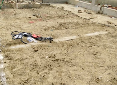
For some practical reasons, it was decided to design the test bench in 1:5 scales. The total dimension of such bench is 12 m in length, 7 m in width and 3 m in depth. The test bench was devided into two parts, one part was designed without any measures, while the other part was set a barrier in each condition (shown as Fig. 1). The excitation and accelerometers installation positions were shown as Fig. 1 as well.
Fig. 1Experimental layout and profile
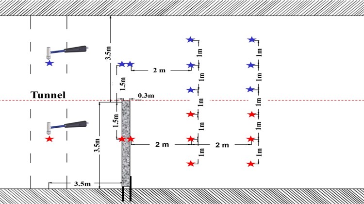
a) Layout of the bench and the positions of excitation and accelerometers
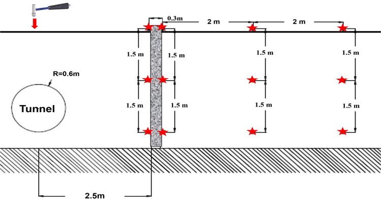
b) Profile of the bench and the positions of excitation and accelerometers
In this paper, four different conditions were introduced, including the control condition, open trench, concrete barriers, and concrete barriers with PUR mat (see Fig. 2). After changed the type of barrier, both control part and barrier part were re-filled together in the same way, the process would guarantee the test always in a consistency and comparable condition. All the barriers were designed in 300 mm in thickness, 3.5 mm in depth and 3 m in width. The open trench was surrounded by 5 mm thickness wooden sheets to keep inside empty. The reinforced concrete barrier was made by C30 concrete and 12 mm steel bars. And in last condition, the 25 mm thickness PUR mat was glued on the concrete surface at the side facing the excitation source.
Measurements were conducted by applying impact excitation using an instrumented hammer. Each response was produced by 5 valid impacts. The coherence curves were carefully controlled to make sure values above 0.8 were obtained.
Fig. 2Test cases
a) Without measures
b) Open trench
c) Concrete barrier
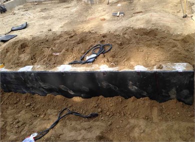
d) Concrete barrier with PUR mat
3. Measurement results
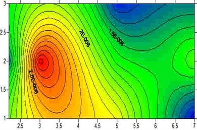
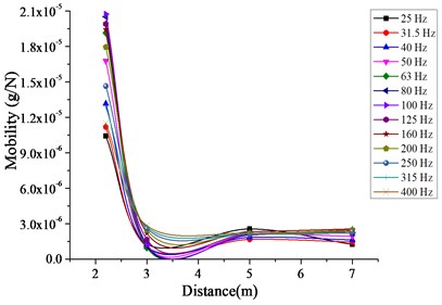
In this paper, the 1/3 octave band mobility of vibration amplitude alternated with the distance was analyzed, and vibration contour was also provided for an intuitional view, as shown in Fig. 3.
From the mobility curve shown in Fig. 3 and Fig. 4, it indicated that:
1) When in control condition, shown as Fig. 3(a) and Fig. 4(a), the vibration amplitude would decrease with the distance. And in the higher frequency range, the vibration is reduced faster. The results coherence with the theoretical definition, the higher frequency vibration (means the longer wavelength) tends to farther transmission.
2) When in the open trench condition, shown as Fig. 3(b) and Fig. 4(b), vibration mitigated behind the trench in some frequency range, and also the vibration was isolated in the shadow behind the trench. However, the vibration re-increased in farther distance.
3) When in the concrete barrier, shown as Fig. 3(c) and Fig. 4(c), the vibration behind the wall was noticed obviously higher than the frontal area. It may because the concrete wall became a new vibration source after absorb the vibration energy in front of it. It indicated that the nature frequency should be taken into consideration when using such a stiff structure as a vibration barrier.
4) After glued a 25 mm thickness elastic PUR layer on the concrete surface at the side facing the excitation source, shown as Fig. 3(d) and Fig. 4(d), dramatic changes happened. The vibration was obvious shielded in frontal area of the barrier in very larger frequency range.
Fig. 3Vibration contour for some typical frequency
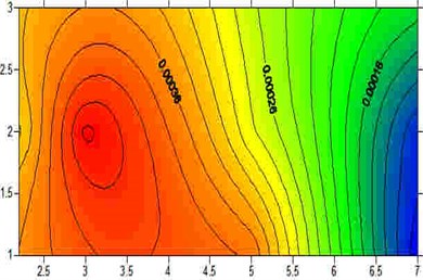
a) Without measures (at 400 Hz)
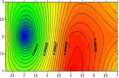
b) Open trench (at 400 Hz)
c) Concrete barrier (at 400 Hz)
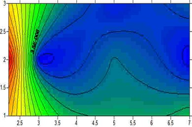
d) Concrete barrier with PUR mat (at 400 Hz)
Fig. 41/3 octave band acceleration mobility
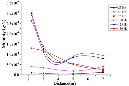
a) Without measures
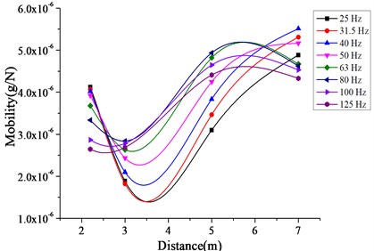
b) Open trench

c) Concrete barrier
d) Concrete barrier with PUR mat
4. Conclusions
Based on the above presented test results, it partly proved some achievements recorded in academic papers, in which the simulation method was mostly used to calculate the vibration mitigation performance by setting measures at the transmission path. However, depends on the discreteness properties of soil and location between vibration source and the protection objects, it hardly to evaluate the vibration isolation efficiency by using open trench and barriers.
However, something positive findings could be noticed from this test campaigns, that is one can conclude that the use of a specific barriers made of concrete with elastic layer, can indeed efficiently reduce the transmission through the soil of vibrations.
References
-
Thompson D. J. Railway Noise and Vibration: Mechanisms, Modelling and Means of Control. Elsevier, Oxford, 2008.
-
Lombaert G., Degrande G., François S., Thompson D. J. Ground-borne vibration due to railway traffic: a review of excitation mechanisms, prediction methods and mitigation measures. Notes on Numerical Fluid Mechanics and Multi Disciplinary Design, Vol. 126, 2015, p. 253-287.
-
Woods R. Screening of surface waves in soils. Journal of the Soil Mechanics and Foundations Division, Vol. 94, Issue 4, 1968, p. 951-979.
-
Richart F. E., Hall J. R., Woods R. D. Vibration of Soils and Foundations. Englewood Cliffs, Prentice-Hall, New Jersey, 1970.
-
Celebi E., Firat S., Beyhan G., Cankaya I., Vural I., Kirtel O. Field experiments on wave propagation and vibration isolation by using wave barriers. Soil Dynamics and Earthquake Engineering, Vol. 29, 2009, p. 824-833.
-
Kim M., Lee P., Kim D., Kwon H. Vibration isolation using flexible rubber chip barriers. Proceedings of the International Workshop Wave, Wave Propagation, Moving Load, Vibration Reduction, Rotterdam, 2000, p. 289-298.
About this article

This work was under the support of Beijing Natural Science Foundation (No. 8164053) and the Postdoctoral Program Funds (2016ZZ-83).
