Abstract
A coupled model of a track-layered ground-in-filled trench system is developed to investigate the isolation effects of an in-filled trench on reducing vibrations generated by moving train loads. By using the substructure method, the whole model is decomposed into two parts: the layered ground containing the in-filled trench and the track. Firstly, the flexibility coefficient for moving uniformly distributed loads applied on the layered ground containing the trench is obtained by using the 2.5D indirect boundary element method. Then, the dynamic equilibrium equation of the track under the moving train loads and uniformly distributed loads are established. Finally, the layered ground and the track are coupled according to the equivalence between the deformation of the track and the vertical displacement of the layered ground. The validity of the method is confirmed by comparing its results with the published ones. Numerical calculations are performed by embedding an in-filled trench in a homogenous ground, in a single layered ground and also in the real site at Ledsgard as examples. The results show that the isolation effects are different for different ground conditions and for different geometric parameters such as the depth, width and location of the in-filled trench.
1. Introduction
In recent years, the rapid development of high-speed trains not only promotes the economy greatly, but also improves people's life significantly. However, train-induced vibration has also been a source of annoyance for line-side residents or buildings with highly sensitive instruments. Therefore, it is of great importance in studying how to reduce the vibrations induced by high-speed trains.
At present, some vibration isolation methods have been adopted to reduce ground vibrations, such as heavy rail and seamless line, isolation fastener, elastic foundation, wave barriers and so on. And wave barriers can be divided into continuous barriers such as isolation trench, bentonite slurry, concrete wall etc. and discontinuous barriers such as rows of openings, sheet-pile walls etc. Isolation can be active and passive. Active isolation is the method of reducing wave energy radiated from the vibration source by setting barriers near the vibration source and passive isolation in contrast is the method of reducing wave energy by setting barriers near the area to be shielded.
A remarkable amount of literatures has been reported to study the reduction of train-induced vibration by wave barriers. Woods [1] summarized the basic standard of wave barriers through a great deal of experiments and adopted an amplitude attenuation factor tomeasure the isolation effectiveness of wave barriers. Beskos et al. [2] studied structural isolation from ground transmitted vibrations by open or in-filled trenches. Yang and Hung [3] investigated the effectiveness of three different wave barriers, i.e., the open trench, in-filled trench, and elastic foundation, in reducing the ground vibrations caused by the passage of trains through a finite/infinite element model. Adam and Von Estorff [4] established a two-dimensional soil-structure system containing the cross-section of a railway embankment, the underlying soil, a trench barrier and a nearby six storey building and described the effect of open and in-filled trenches in reducing the building vibrations due to passing trains. Hung et al. [5] studied the effectiveness of different vibration countermeasures (open trenches, in-filled trenches, and wave impeding blocks) in isolating the ground vibrations induced by trains moving at sub- and supercritical speeds, with respect to the Rayleigh wave speed of the soils. Andersen and Nielsen [6] employed a coupled finite element-boundary element model to examine the influence of the track design and properties on the level of ground vibration due to a vehicle. With et al. [7] presented a comparison between measured train-induced ground vibrations in the free-field before and after countermeasures had been taken at Kahog in Sweden and used two-dimensional finite element model to study the relative importance of the wave barrier and the noise-embankment. Deng et al. [8] analyzed the efficiency of vibration isolating groove's depth, width and position to the vibration caused by vehicle load using FEM and NEWMARK implicit integration algorithm. Gao et al. [9] established 2.5D finite element model of train-track-ground-vibration countermeasures and analyzed the effectiveness of different vibration countermeasures including open trench, in-filled trench and concrete slab in isolating the ground vibrations induced by trains moving at sub- and high-speeds. Other researches in this area in recent years are carried out by Hildebrand [10], Yang et al. [11], Jesmani et al. [12], Tsai [13], and Zakeri et al. [14]. In a recent study, Kim [15] studied the characteristics and the reduction methods of ground vibration due to the tilting train. Chiang and Tsai [16] examined the screening effectiveness of open trenches on reducing vibration generated by a high-speed train using 2D boundary element method in time domain. Esmaeili et al. [17] firstly used a V-shaped trench to investigate the effect of the trench’s shape on its performance.
It should be noted that the above studies are restricted to the homogenous ground. However, the layered ground is more common and dynamic responses of the layered ground can be significantly different from the homogenous case according to the author's previous study [18]. At present, there are few studies reported to investigate the isolation effects by using the layered ground model. Banerjee et al. [19] and Leung et al. [20] studied the problem of isolating structures from surface waves by open or filled trenches in layered medium using the Green's function. Karlstrom and Bostrom [21] adopted a 3D analytical approach to account for trenches on one or both sides close to a railroad and the ground was modelled as a layered semi-infinite domain. Di Mino et al. [22] analyzed several open trench configurations such as width and depth, distance from the rail, thickness of the soil layer over the rigid bedrock, type of the ground, ratio between the depth of the trench, and the thickness of the soil layer. Sivakumar Babu et al. [23] used finite difference tool FLAC 5.0 to suggest effective vibration isolation systems. Connolly et al. [24] undertook a geophysical investigation on a high speed railway line outside Edinburgh, Scotland and established a 3D finite element railway model using commercially available software to mitigate vibration levels. Jiang et al. [25] studied two mitigation measures-open trenches and buried soft wall barriers using coupled finite element-boundary element models. Gao et al. [26] analyzed the effectiveness of passive vibration isolation by open trench in upper soft-layer and lower stiff-layer visco-elastic foundations in detail. Yuan et al. [27] built a model for open trenches in a saturated ground and investigated the vibration-isolation effects of open trenches in three saturated grounds (homogeneous saturated ground, layered saturated ground and saturated ground with upper layer being single-phase elastic medium).
In this paper, a coupled model of track-layered ground-wave barrier is established and the in-filled trench with rectangular cross-section serves as the barrier. And the isolation effects of the in-filled trench are studied in detail. The rest of the paper is organized as follows. Firstly, the method is introduced in detail. Secondly, the accuracy of the method is verified by comparing its results with the published ones. Thirdly, numerical calculations are performed by embedding the in-filled trench in a homogenous ground and in a single soil layered ground as examples and the effects of depth, width and location of the in-filled trench on the isolation effects for the sub-, trans- and supersonic speed train loads are studied specifically. Finally, the proposed method is used to investigate the isolation effects of the Swedish high-speed train X-2000 induced vibration at Ledsgard by using the in-filled trench.
2. Model and methodology
A track resting on a layered ground containing an in-filled trench is illustrated in Fig. 1. The geometric parameters of the trench are defined as follows: trench depth of , trench width of , distance from the track to the centerline of the trench as . The layered ground is formed by horizontal layers and the underlying half-space. Each of the media forming the layered ground is assumed to be slightly dissipative and is characterized by the shear wave velocity , the mass density , Poisson’s ratio , and the hysteretic damping ratio ( 1, ). The underlying half-space is characterized by the complex S-wave velocity , the mass density , Poisson’s ratio , and the hysteretic damping ratio . The in-filled trench is characterized by the shear wave velocity , the mass density , Poisson’s ratio , and the hysteretic damping ratio . The track system comprising rails, sleepers and ballast bed is modeled by an Euler beam with the mass per unit length being and a bending rigidity being . And the width of the track is (). Point A (6 m, 0 m, 0 m) and Point B (13 m, 0 m, 0 m) are the two observation points.
Fig. 1The coupled model of a track -layered ground-trench system
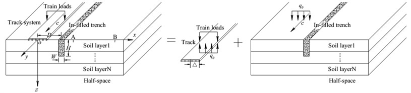
To solve the problem, the substructure process is introduced. And the whole model is decomposed into two parts: the track and the layered ground containing the in-filled trench (Fig. 1). Firstly, the flexibility coefficient of a layered ground containing an in-filled trench under moving uniformly distributed line loads is obtained. Then, the dynamic equilibrium equation of the track under the moving train loads and also the moving uniformly distributed line loads is established. Finally, the two parts are assembled together according to the equivalence between the deformation of the track and the vertical displacement of the layered ground.
A 2.5D indirect boundary element method is proposed to obtain the flexibility coefficient of the layered ground containing the in-filled trench. It is assumed that the train speed is constant, and also the track properties and the soil parameters of every cross-section vertical to the direction of the track are the same. The 2.5D formulation reduces the discretization effort to the cross-section of the in-filled trench by exploring the particular feature of dynamic response repeating themselves with a certain delay of time in time domain (a certain delay of phase in frequency domain) when the train moving with a constant speed. The 2.5D indirect boundary element method will be described in detail in the following subsection. To calculate the flexibility coefficient conveniently, we decompose the layered ground containing the in-filled trench into two parts: domain outside of the in-filled trench and domain inside of the in-filled trench. Further, we define the total wave fields outside of the in-filled trench as the summation of the free field responses and the scattered field responses, and the total wave fields inside of the in-filled trench as the scattered field responses only. The free wave fields are defined as the train-induced dynamic responses (displacements and tractions) in a layered ground without the in-filled trench. And the scattered wave fields are defined as the additional wave fields due to the inhomogeneity of the in-filled trench. The scattered wave fields outside and inside of the in-filled trench are simulated by applying two sets of virtual moving uniformly distributed line loads on the boundary of the in-filled trench. The densities of the two sets of moving uniformly distributed line loads can be obtained by introducing the boundary conditions. Finally, the total wave fields outside of the in-filled trench are obtained by adding the free wave fields to the scattered ones, in other words the flexibility coefficient of a layered ground containing the in-filled trench is obtained.
2.1. The flexibility coefficient of the layered ground containing the in-filled trench
2.1.1. Free wave fields responses
The free wave fields responses are calculated by using the direct stiffness method. The procedures are as follows. Uniformly distributed line load with width and density moving along the y direction (Fig. 1) can be expressed as:
where is the moving velocity and is the Dirac function. Performing Fourier transformation on Eq. (1) with respect to the two horizontal coordinates and also with respect to time, the load amplitude in frequency and wave number domains can be expressed as:
where and are the wave numbers with respect to and . is the circular frequency with respect to the time . The discrete dynamic equation of the layered ground under can be written as:
where is the vector of displacement amplitudes at the layer’s interfaces. is the three dimensional dynamic stiffness of the layered ground [28]. Solving Eq. (3), the displacement amplitudes at the upper and bottom interfaces of each layer are obtained and then the amplitudes of the up-going and down-going waves in the corresponding layer are obtained. Finally, the displacements , and and tractions , and in frequency and wave number domains can be obtained through the relationship between the dynamic responses and the amplitudes of up-going and down-going waves.
It should be noted that the above calculations are performed in frequency and wave number domains, and the dynamic responses in time and space domains can be obtained by using inverse Fourier transformation given by Eq. (4):
where, is the dynamic response in frequency and wave number domains, is the response in time and space domains.
2.1.2. Scattered wave fields responses
As stated above, the scattered wave fields outside and inside of the in-filled trench can be simulated by applying two sets of virtual moving loads on the boundary of the in-filled trench. This method is also called the Green's functions method. In this paper, the used Green’s functions include Green’s functions for moving uniformly distributed loads acting on a horizontal line and also on a vertical line in a layered ground. The Green’s functions for moving uniformly distributed loads acting on a horizontal line in a layered ground can refer to Ref. [29]. As to the Green’s functions for moving uniformly distributed loads acting on a vertical line, the main procedures are as follows (Fig. 2). Firstly, the moving uniformly distributed loads are transformed into the frequency and wave number domains. And in the transformed domain, the moving uniformly distributed loads are fixed by introducing two additional interfaces at their upper and bottom boundaries to obtain the dynamic responses restricted in the fixed layer and the corresponding reaction forces , , , , and . Secondly, the dynamic responses of the reaction forces are determined by applying them with opposite sign to the whole layered ground. And the dynamic responses due to the reaction forces are obtained by direct stiffness method. Thirdly, dynamic responses restricted in the fixed layer are added to those of reaction forces to obtain the global ones. Finally, dynamic responses in the frequency and wave number domains are retrieved by inverse Fourier transformation.
Fig. 2Dynamic Green’s functions for moving uniformly distributed loads acting on a vertical line in a layered ground
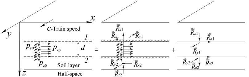
As is shown in Fig. 2, uniformly distributed loads in the , and directions moving along the axis can be expressed as:
with , , being the uniformly distributed loads densities in the directions of , , , respectively. Performing Fourier transformation with respect to the two horizontal coordinates and also with respect to time on Eq. (5), the loads amplitudes in frequency and wave number domains can be expressed as:
The displacements, which varied as in the two horizontal directions and also as in frequency domain, can be expressed as:
where , and are the corresponding displacements amplitudes. The harmonic dynamic equilibrium equation can be expressed as:
where is the vector of the virtual moving uniformly distributed loads. and are the two complex Lamb constants. is the hysteretic damping ratio. By inspection, the amplitudes of the particular solutions (identified with superscript ‘’) of Eq. (8) can be specified as:
By substituting Eq. (9) into Eq. (8) and identifying the constant terms, the following equation for the three constants (, and ) are obtained:
where:
Substituting the coefficients , , solved by Eq. (10) into Eq. (9), and introducing 0 and into Eq. (9), the amplitudes of displacements , , , , , and at the upper and bottom interfaces of the fixed layer can be obtained. And then the amplitudes of particular reaction forces are obtained with , , , , and .
To fix the two interfaces, the homogeneous solutions (identified with superscript corresponding to the negative values of , , , , , and must be imposed on the particular ones. The external loads (homogenous reactions) , , , , and result from:
where is the exact 3-D stiffness matrix of the layer which can refer to Ref. [28]. The total external loads at the top and bottom of the fixed layer which need to be applied on the total layered half-space are equal to:
Substituting Eq. (12) into discrete dynamic equation of the layered ground (assuming the vertical load locates in the th layer), we have:
Solving Eq. (13), the displacements amplitudes at the upper and bottom interfaces of each soil layer are obtained, and then the amplitudes of the up-going and down-going waves are obtained. Finally, the displacements and tractions at every point can be obtained through the relationship between the dynamic responses and the amplitudes of up-going and down-going waves.
It should be noted that the above calculations are also performed in frequency and wave number domains which is the same as the calculation for the free wave fields, and the Green’s functions in frequency and space domain can be obtained with the inverse Fourier transformation.
Letting and are the displacements and tractions Green’s functions for the layered ground (outside of the in-filled trench) and and are the displacements and tractions Green’s functions for the in-filled trench, the displacements and tractions in the region of the layered ground and in the region of the in-filled trench can be expressed as:
where the subscript ‘’ indicates results attributable to the moving uniformly distributed loads, while the superscripts ‘’ and ‘’ denote parameters associated with the layered ground and the in-filled trench, respectively. and are the load vectors acting on the interface to calculate the Green’s functions for layered ground and the in-filled trench, respectively.
2.1.3. Boundary conditions
The boundary conditions on the interface of the in-filled trench (continuity of displacement and traction) can be expressed as:
where, , , , , , are the tractions and displacements on the interface corresponding to the layered ground; , , , , , are the tractions and displacements on the interface corresponding to the in-filled trench; , , , , , are the tractions and displacements on the interface corresponding to the free wave field; For simplicity, , the weighting function, is chosen as a unite matrix to calculate the integral over each element separately. Substituting Eq. (14) into Eq. (15) gives:
where:
Solving Eq. (16), the two sets of virtual loads and are obtained. Substituting loads into Eq. (14a), the scattered fields for the displacements are obtained. Finally, the total displacements at every point in the layered ground are obtained by adding the free field responses to the scattered field responses:
And Eq. (17) can be rewritten as:
where , , are the flexibility coefficients in the , , and directions of the layered ground containing an in-filled trench under moving uniformly distributed loads, is the moving vertical uniformly distributed load and is the vector of the displacements.
It should be noted that the above calculations are performed in frequency domain, and the displacement, velocity and acceleration in time domain can be obtained by using inverse Fourier transformation:
2.2. Couple the layered ground and the track
Assuming the interaction force between the track and the layered ground is the dynamic equilibrium equation can be expressed as:
where is the deformation of the track, is the summation of the axle loads and the detailed expression can refer to [29]. Performing Fourier transformation on Eq. (22), the following equation is obtained:
The layered ground and the track are coupled by letting the deformation of the track equal to the vertical surface displacement of the layered ground containing the in-filled trench:
where is the vertical flexibility coefficient of a layered ground containing an in-filled trench. Combining Eqs. (23) and (24), the interaction forces can be obtained. Substituting the interaction force into Eq. (22), the deformation of the track is obtained. Substituting the interaction force into Eq. (18), the displacement responses in frequency-space domain are obtained and the displacement, velocity and acceleration responses at every point in time-space domain are obtained by Eq. (19), Eq. (20) and Eq. (21).
3. Verification of the method
To verify the accuracy of the presented method, our results are firstly compared with those of article [30, 31] which examined the screening effectiveness of open trenches on reducing vibration generated by a high-speed train using the 2D boundary element method. To compare, we set the shear velocity of the in-filled trench as 1 m/s and (by setting , the presented 2.5D formulation in this paper reduces to the 2D case and setting the shear of the in-filled trench as 1 m/s to obtain an open trench). The model of uniformly distributed load acting on a homogenous ground containing an open trench is illustrated in Fig. 3. The material properties of the homogenous ground are as follows: the shear modulus 132 MN/m2, Poisson ratio 0.25, mass density 1785.7 kg/m3, shear velocity 271.88 m/s. The material damping is not included in this study. A uniform traction is subjected to a zone of 22 m in width. The time history of traction is a triangular impulse (amplitude of impulse 1 MN/m2). The rise-time of the load is 0.002 s, and the duration of the load is 0.004 s. The distance from the center of the loading zone to the center of the open trench (width: 1 m and depth: 3 m) is 11.5 m.
Fig. 3Model of an opened trench to reduce ground vibration
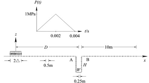
The vertical displacement time history of Point A (10 m, 0 m) and Point B (13 m, 0 m) shown in Fig. 3 are illustrated in Fig. 4 and the dimensionless time and dimensionless displacement are defined as follows: , . As can be seen from Fig. 4, our results are very close to those obtained by Israil and Banerjee [30] and also by Chiang and Tsai [31]. This validates the accuracy of our method. And it should be noted that Israil and Banerjee [30] used the full-space Green’s function to formulate their boundary element method, so that the free surface of the ground also needed to be discretized. And we use the half-space Green’s functions in the present indirect boundary element method, so that only the free surface of the open trench needed to be discretized.
Fig. 4Comparison between the results obtained by the presented method with those of Israil and Banerjee [30] and Chiang and Tsai [31]
![Comparison between the results obtained by the presented method with those of Israil and Banerjee [30] and Chiang and Tsai [31]](https://static-01.extrica.com/articles/16566/16566-img4.jpg)
a) Displacement time history at Point A without the trench
![Comparison between the results obtained by the presented method with those of Israil and Banerjee [30] and Chiang and Tsai [31]](https://static-01.extrica.com/articles/16566/16566-img5.jpg)
b) Displacement time history at Point A with the trench
![Comparison between the results obtained by the presented method with those of Israil and Banerjee [30] and Chiang and Tsai [31]](https://static-01.extrica.com/articles/16566/16566-img6.jpg)
c) Displacement time history at Point B without the trench
![Comparison between the results obtained by the presented method with those of Israil and Banerjee [30] and Chiang and Tsai [31]](https://static-01.extrica.com/articles/16566/16566-img7.jpg)
d) Displacement time history at Point B with the trench
Then, our results are compared with those [32] of the Swedish high-speed train X-2000 measured by Swedish National Railway Administration in 1997-1998. To compare, we set the material parameters of the in-filled trench the same as the layered ground to obtain a homogenous layered half-space (without in-filled trench). The material parameters of the layered ground are listed in Table 1. The track properties are given in Table 2. Fig. 5 illustrates the Swedish Railway X-2000 high-speed train with five cars and the axle loads at the precise positions on each individual car are taken into account as indicated in Table 3. Fig. 6 illustrates the deformations of the track obtained by the presented method with those of the actual field measurements for different train speeds. As can be seen, our results are in good agreement with those of the article [32].
Fig. 5X-2000 train geometry and axle loads
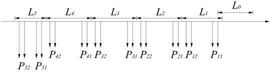
Table 1Soil parameters for train speeds of 70 and 200 km/h
Soil layer | Thickness / m | Mass density / (kg/m3) | Shear velocity / (m/s) | Poisson ratio | Damping ratio | ||
70 km/h | 200 km/h | 70 km/h | 200 km/h | ||||
Surface crust | 1.1 | 1500 | 72 | 65 | 0.49 | 0.04 | 0.063 |
Organic clay | 3.0 | 1620 | 41 | 33 | 0.49 | 0.02 | 0.058 |
Clay | 4.5 | 1475 | 65 | 60 | 0.49 | 0.05 | 0.098 |
Clay | 6.0 | 1475 | 87 | 85 | 0.49 | 0.05 | 0.064 |
Half-space | ∞ | 1475 | 100 | 100 | 0.49 | 0.05 | 0.060 |
Table 2Track properties
Train speed | Track width / m | Mass density / (kg/m) | Bending rigidity / (MN/m2) | Damping ratio |
70 km/h | 3.0 | 10.8E3 | 200E6 | 0.1 |
200 km/h | 3.0 | 10.8E3 | 80E6 | 0.1 |
Table 3Train geometry
Car number | 5 | 4 | 3 | 2 | 1 |
/ kN / kN | 181.5 180.0 | 122.5 122.5 | 122.5 122.5 | 122.5 122.5 | 122.5 122.5 |
/ m | 2.9 | 2.9 | 2.9 | 2.9 | 2.9 |
/ m | 6.6 | 14.8 | 14.8 | 14.8 | 11.6 |
/ m | 17.17 | 24.4 | 24.4 | 24.4 | 22.17 |
Fig. 6Comparison between the results obtained by the presented method with those of field measurements
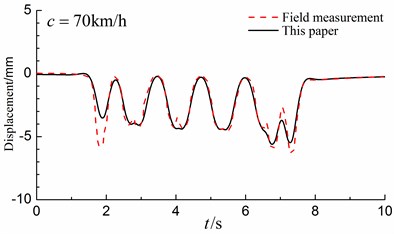
a) 70 km/h
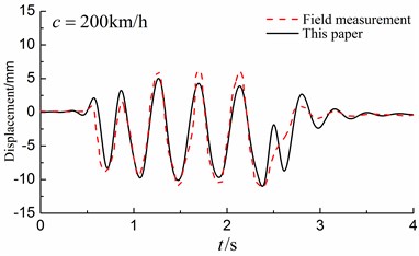
b) 200 km/h
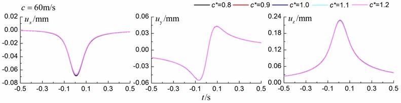
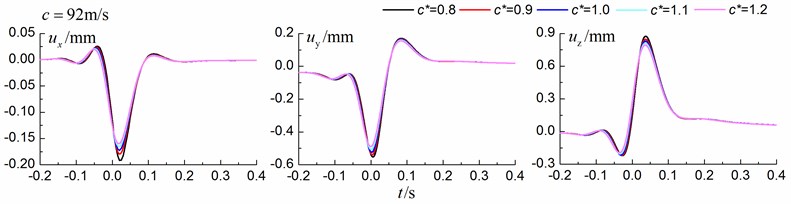
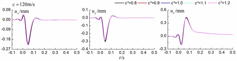
As the parameters of the in-filled trench approach the parameters of the ground, the dynamic responses should approach the dynamic responses of the free field (dynamic response of the ground without the trench). Motivated by this idea, the time history curves of the displacement and also the corresponding maximum values for different shear wave velocity ratios between the in-filled trench and the homogenous ground are compared. The parameters of the homogenous ground are listed in Table 6. The shear wave velocity ratios are 0.8, 0.9, 1.0, 1.1, 1.2 and the corresponding parameters of the in-filled trench are listed in Table 4. Track properties are as follows: Track width 3 m, mass density 10.8×10³ kg/m, bending rigidity 200×106 MN∙m2, damping ratio 0.1. The axle load is one car of 160 kN. The train speeds are 60 m/s (subsonic cases), 92 m/s (transonic cases) and 120 m/s (supersonic cases) with respect to the Rayleigh wave velocity of the homogenous ground.
Fig. 7 shows the time history curves of the displacement in the , and directions at point A (Fig. 1) and Table 5 show the corresponding maximum values. The depth of the in-filled trench is 3 m, the width of the in-filled trench is 1 m and the distance between the center of in-filled trench and the track is 4 m. As is shown in Fig. 7 and Table 5, the time history curves approach the time history curves of the free filed with the shear wave velocity ratio getting closer to 1.0, especially for subsonic and supersonic cases, which give additional confidence of our method.
Table 4Soil parameters inside of the in-filled trench
Shear velocity / (m/s) | Mass density / (kg/m3) | Poisson ratio | Damping ratio |
80 | 2000 | 0.25 | 0.05 |
90 | 2000 | 0.25 | 0.05 |
100 | 2000 | 0.25 | 0.05 |
110 | 2000 | 0.25 | 0.05 |
120 | 2000 | 0.25 | 0.05 |
Table 5The amplitudes of the time history curves
0.8 | 0.9 | 1.0 | 1.1 | 1.2 | ||
60 m/s | / mm | 0.0689 | 0.0684 | 0.0679 | 0.0675 | 0.0670 |
/ mm | 0.0546 | 0.0548 | 0.0548 | 0.0547 | 0.0545 | |
/ mm | 0.2280 | 0.2278 | 0.2273 | 0.2266 | 0.2258 | |
92 m/s | / mm | 0.1916 | 0.1808 | 0.1724 | 0.1657 | 0.1602 |
/ mm | 0.5566 | 0.5416 | 0.5255 | 0.5090 | 0.4916 | |
/ mm | 0.8767 | 0.8496 | 0.8322 | 0.8140 | 0.7960 | |
120 m/s | / mm | 0.2297 | 0.2273 | 0.2252 | 0.2217 | 0.2179 |
/ mm | 0.3062 | 0.2987 | 0.2922 | 0.2884 | 0.2839 | |
/ mm | 0.4335 | 0.4255 | 0.4196 | 0.4149 | 0.4109 |
Fig. 7The time history curves of the displacement for different in-filled trenches
4. Numerical results and analyses
In practical engineering, stiff in-filled trench are widely used. And the isolation effects of the rigid barriers (/1, and are shear velocities of the in-filled trench and ground respectively) are stable. Therefore, for all the calculations in this paper, the parameters of the in-filled trench are kept invariant with the shear velocity 500 m/s, the density 2400 kg/m3, the Poisson’s ratio 0.25, and the damping ratio 0.01.
4.1. Results for the homogenous ground and the single layered ground
In this section, we will take the homogenous ground and also the single layered ground as examples to study the isolation effects due to the in-filled trench. Firstly, the influences of the trench depth, trench width, and location between the in-filled trench and the track on the ground vibrations are studied by using the homogenous ground model. Then the isolation effects to the single layered ground are studied. Finally, the isolation effects to the homogenous ground are compared with those to the single layered ground. The soil parameters are listed in Table 6. Track properties are as follows: Track width 3 m, mass density 10.8×10³ kg/m, bending rigidity 200×106 MN∙m2, damping ratio 0.1. The axle load is one car of 160 kN. The train speeds are 60 m/s (subsonic cases), 92 m/s (transonic cases) and 120 m/s (supersonic cases) with respect to the Rayleigh wave speed of the soils.
Table 6Soil parameters of the homogenous ground and the layered ground
soil layer | Homogenous ground | layered ground |
Soil’s shear velocity / (m/s) | 100.0 | 100.0 |
Half-space’s shear velocity / (m/s) | 100.0 | 200.0 |
Mass density () / (kg/m3) | 2000.0 | 2000.0 |
Poisson ratio () | 0.25 | 0.25 |
Thickness / m | – | 5 m |
Damping ratio () | 0.05 | 0.05 (0.02) |
4.1.1. Results for the homogenous ground
4.1.1.1. The effect of trench depth
Figs. 8-10 shows the time history curves of the displacement, velocity and acceleration in the , and directions at point A for different trench depths of 0 m, 3 m, 5 m and 7 m in a homogenous ground. 0 represents ground without the trench. The load is moving with subsonic, transonic and supersonic speeds, respectively. The width of the in-filled trench is 1 m and the distance between the in-filled trench and track is 4 m.
As is shown in Figs. 8-10, we can find that trench depth has a great influence on isolation effects. The amplitudes of the dynamic responses reduce greatly with the increase of the in-filled trench depth for all the three moving speeds and for all the three directions. The isolation effects are better for the vertical vibration than those for the two horizontal vibrations. Besides, the in-filled trench tends to isolate vibrations induced by the transonic and supersonic train more effectively than those induced by the subsonic train. In addition, the peaks of point A’s displacement, velocity and acceleration curves arrive earlier than those of free field under transonic and supersonic cases due to the rigid in-filled trench. And it should be noted that the supersonic train induces the strongest vibrations and we will mainly discuss the isolation effects corresponding to the supersonic train.
4.1.1.2. The effect of trench width
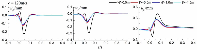
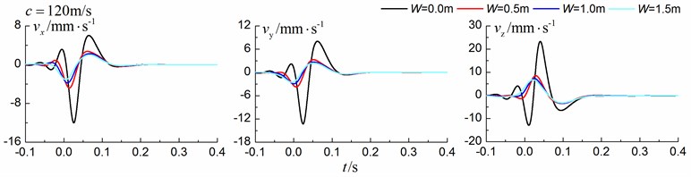
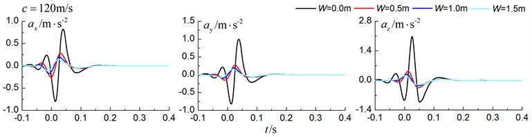
Fig. 11 shows the time history curves of the displacement, velocity and acceleration in the , and directions at point A for different trench widths of 0.0 m, 0.5 m, 1 m and 1.5 m in a homogenous ground. 0.0 m represents ground without the trench. The load is moving with supersonic speed. The depth of the in-filled trench is 3 m and the distance between the in-filled trench and track is 4 m. As is shown in Fig. 11, it is clear that the width of the in-filled trench does not have much influence on the insertion loss and the isolation effects improve slowly with the increase of the trench width.
Fig. 8Influence of trench depth on isolation effects in a homogenous ground under subsonic train
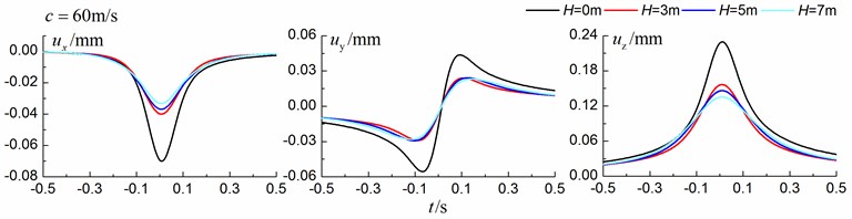
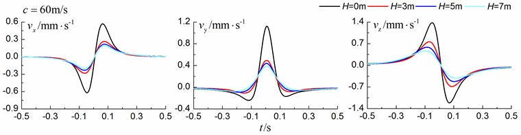
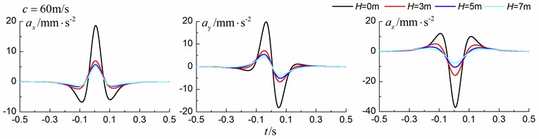
Fig. 9Influence of trench depth on isolation effects in a homogenous ground under transonic train
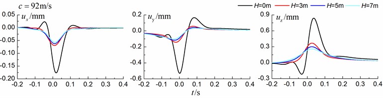
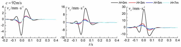
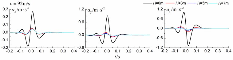
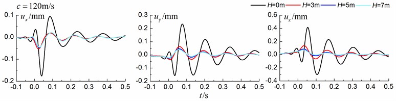
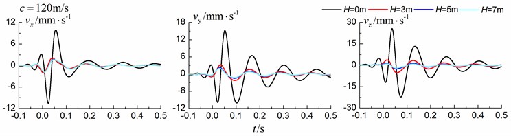
Fig. 10Influence of trench depth on isolation effects in a homogenous ground under supersonic train
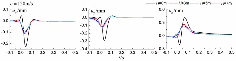
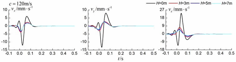
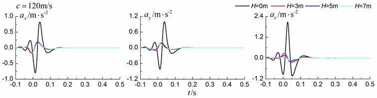
Fig. 11Influence of trench width on isolation effects in a homogenous ground
4.1.1.3. The effect of distance from the track to the center of the in-filled trench
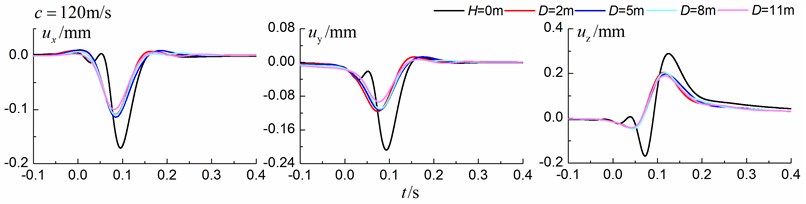
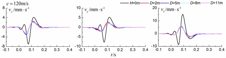
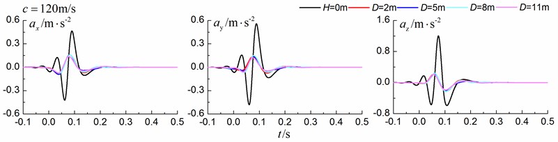
Fig. 12 shows the time history curves of the displacement, velocity and acceleration in the , and directions at point B for different trench locations from the track to the center of the in-filled trench of 2 m, 5 m, 8 m and 11 m in a homogenous ground. 0 m represents ground without the trench. The load is moving with supersonic speed. The depth of the in-filled trench is 3 m and the width of the trench is 1 m. As is shown in Fig. 12, it is clear that the location of the trench has little influence on the insertion loss
Fig. 12Influence of trench location on isolation effects in a homogenous ground
4.1.2. Results in a single layered ground
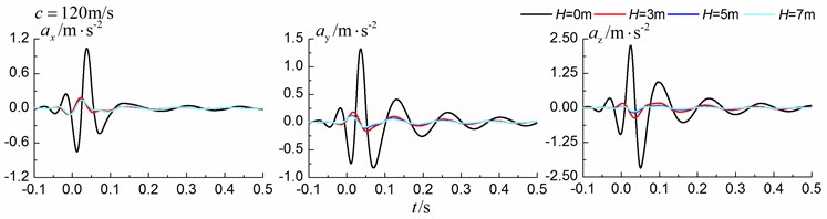
Figs. 13-15 shows the time history curves of the displacement, velocity and acceleration in the , and directions at point A for different trench depths of 0 m, 3 m, 5 m and 7 m in a layered ground. 0 represents ground without the trench. The load is moving with subsonic, transonic and supersonic speed. The width of the in-filled trench is 1 m and the distance between the in-filled trench and track is 4 m. As is shown in Figs. 13-15, it can be easily observed that trench depth has a great influence on isolation effects. Similar to the homogenous ground case, the amplitudes of the dynamic responses reduce greatly with the increase of the in-filled trench depth for all the three moving speeds and for all the three directions, however, the isolation effects of 5 m and 7 m have little difference. In addition, the peaks of point A’s displacement, velocity and acceleration curves arrive earlier than those of free field under transonic and supersonic cases.
Fig. 13Influence of trench depth on isolation effects in a layered ground under subsonic train
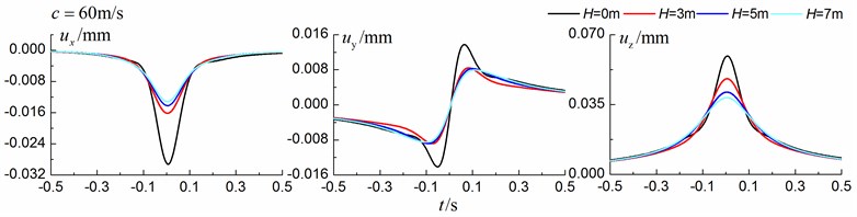
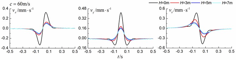
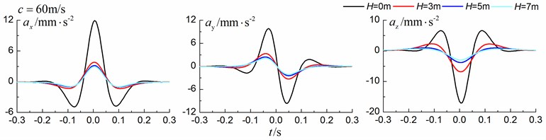
Fig. 14Influence of trench depth on isolation effects in a layered ground under transonic train
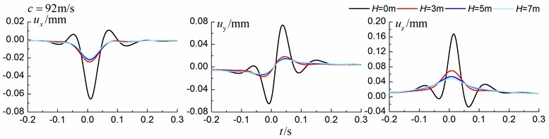
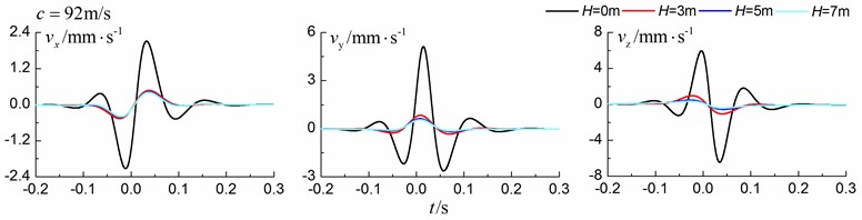
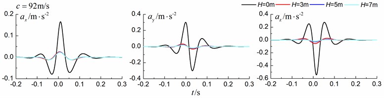
Fig. 15Influence of trench depth on isolation effects in a layered ground under supersonic train
4.1.3. Comparison of the homogenous ground and the single layered ground
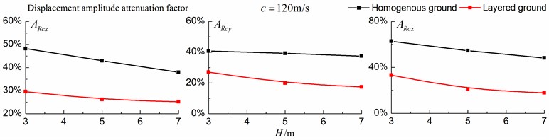
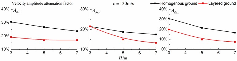
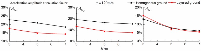
Figs. 16-18 shows the amplitude attenuation curves of the displacement, velocity and acceleration in the , and directions at point A for different trench depths of 0 m, 3 m, 5 m and 7 m in a homogenous ground and in a single layered ground. The load is moving with subsonic, transonic and supersonic speeds. The width of the in-filled trench is 1 m and the distance between the in-filled trench and track is 4 m. The amplitude attenuation factor is defined as follows:
As is shown in Figs. 16-18, for subsonic cases, the displacement isolation effects of in-filled trench in the direction of y in a homogenous ground are better than those in a layered ground, but there is no great difference between the two foundations in the velocity, acceleration isolation effects of direction and also in the displacement, velocity, acceleration isolation effects of , direction. For transonic cases, the velocity isolation effects in the direction of in the homogenous ground are better than those in the layered ground when the trench’s depth is 5 and 7 meters, but in other situations, the isolation effects are better in the layered ground. For supersonic cases, there is no great difference in the vertical acceleration isolation effects between the two foundations, but in general, the isolation effects in the layered ground are better than those in the homogenous ground. In addition, the in-filled trench tends to isolate vibrations induced by the transonic and supersonic train more effectively than vibrations induced by the subsonic train for both in the homogenous ground and in the layered ground.
Fig. 16Comparison of isolation effects in a homogenous ground and in a layered ground under subsonic train
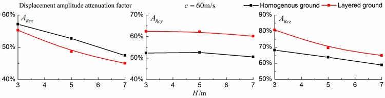
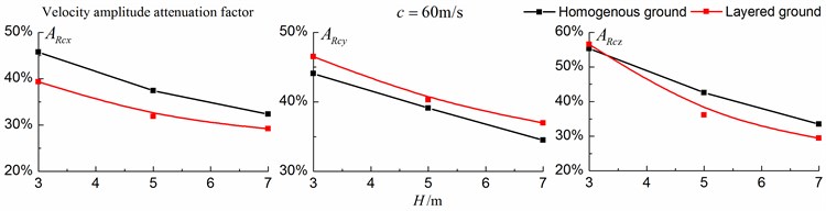
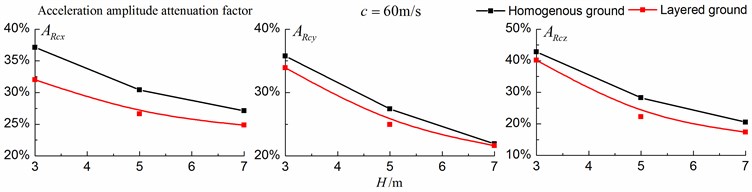
Fig. 17Comparison of isolation effects in a homogenous ground and in a layered ground under transonic train
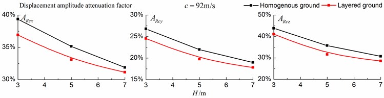
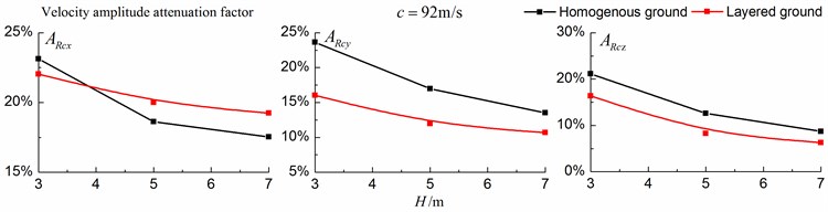
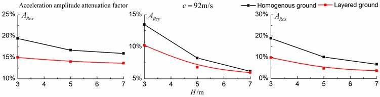
Fig. 18Comparison of isolation effects in a homogenous ground and in a layered ground under supersonic train
4.2. Analysis of the actual layered ground
In this subsection, the isolation effects of Swedish high-speed train X-2000 at Ledsgard running on the soft layered ground by using the in-filled trench are studied. The values of the soil properties [33] are listed in Table 7. The track properties are given in Table 2. Fig. 5 illustrates the Swedish Railway X-2000 high-speed train and the axle loads are indicated in Table 3.
Table 7Soil parameters for train speeds of 70 and 200 km/h
Soil layer | Thickness / m | Mass density / (kg/m3) | Shear velocity / (m/s) | Poisson ratio | Damping ratio | ||
70 km/h | 200 km/h | 70 km/h | 200 km/h | ||||
Surface crust | 1.0 | 1500 | 72 | 65 | 0.39 | 0.04 | 0.063 |
Organic clay | 3.0 | 1620 | 41 | 33 | 0.35 | 0.02 | 0.058 |
Clay | 4.5 | 1475 | 65 | 60 | 0.41 | 0.05 | 0.098 |
Clay | 7.0 | 1475 | 87 | 85 | 0.33 | 0.05 | 0.064 |
Half-space | ∞ | 1475 | 100 | 100 | 0.33 | 0.05 | 0.060 |
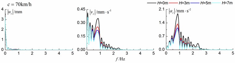
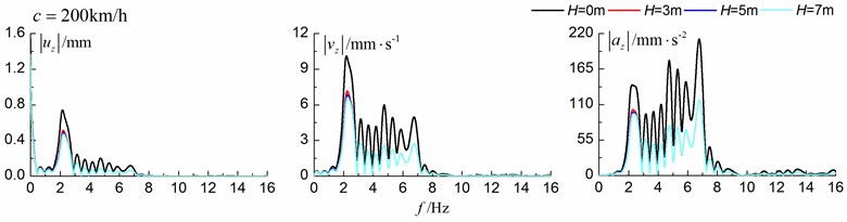
Fig. 19 and Fig. 20 show the time history curves and the Fourier amplitude spectrums, respectively, of the vertical displacement, velocity and acceleration at point A (Fig. 1) for different trench depths of 0 m, 3 m, 5 m and 7 m. 0 represents ground without the trench. The moving speed can be low (70 km/h) and high (200 km/h). The width of the in-filled trench is 1 m and the distance between the in-filled trench and track is 4 m.
As is shown in Fig. 19, the dynamic vibrations reduce greatly with the increase of the depth of the in-filled trench, especially for train moving with high speed (200 km/h). In addition, it seems that the isolation effects of the velocity and acceleration are more significant than those of the displacement.
From the results in Fig. 20, it can be easily observed that the in-filled trench has a great influence on the frequency spectrums and the in-filled trench isolates dynamic responses for the high frequency more effectively than those for the low frequency. Furthermore, the responses spectrums migrate to high frequency with the increase of train speed, which is the very reason why the isolation effects for the higher speed (200 km/h) are better than those for the lower speed (70 km/h). And the accelerations and velocities contain more high frequencies than those of the displacements, which is the very reason why the in-filled trench reduces the amplitudes of the accelerations and velocities more efficiently than those of the displacements.
Fig. 19Influence of trench depth on the isolation effects
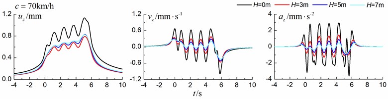
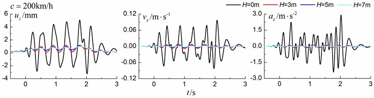
Fig. 20Influence of trench depth on the Fourier spectrums
5. Conclusion
1) The isolation effects improve with the increase of the in-filled trench depth for all the subsonic, transonic and supersonic speeds.
2) In general, the isolation effects of the in-filled trench in the layered ground are better than those in the homogenous ground. In addition, the in-filled trench tends to isolate the vibrations for the transonic and supersonic moving train loads more effectively than those for the subsonic case.
3) The width of the in-filled trench does not have much influence on the insertion loss with the isolation effects improving slowly with the increase of trench width. The location of the in-filled trench also has little influence on the isolation effects.
4) Studying the isolation effects of Swedish high-speed train X-2000 at Ledsgard running on the soft layered ground show that the in-filled trench isolates dynamic responses for the high frequency more effectively than for the low frequency.
References
-
Woods R. D. Screening of surface waves in soils. Journal of the Soil Mechanics and Foundations Division, Vol. 94, Issue 4, 1968, p. 951-980.
-
Beskos D. E., Dasgupta Vardoulakis B. I. G. Vibration isolation using open or filled trenches. Computational Mechanics, Vol. 1, Issue 1, 1986, p. 43-63.
-
Yang Y. B., Hung H. H. A parametric study of wave barriers for reduction of train-induced vibrations. International Journal for Numerical Methods in Engineering, Vol. 40, 1997, p. 3729-3747.
-
Adam M., von Estorff O. Reduction of train-induced building vibrations by using open and filled trenches. Computers and Structures, Vol. 83, 2005, p. 11-24.
-
Hung H. H., Yang Y. B., Chang D. W. Wave Barriers for reduction of train-induced vibrations in soils. Journal of Geotechnical and Geoenvironmental Engineering, Vol. 130, Issue 12, 2004, p. 1283-1291.
-
Andersen L., Nielsen S. R. K. Reduction of ground vibration by means of barriers or soil improvement along a railway track. Soil Dynamics and Earthquake Engineering, Vol. 25, Issues 7-10, 2005, p. 701-716.
-
With C., Bahrekazemi M., Bodare A. Wave barrier of lime-cement columns against train-induced ground-borne vibrations. Soil Dynamics and Earthquake Engineering, Vol. 29, 2009, p. 1027-1033.
-
Deng Yahong, Xia Tangdai, Chen Jingyu Analysis of efficiency of vibration isolating groove subjected to vehicle load. Rock and Soil Mechanics, Vol. 28, Issue 5, 2007, p. 883-888, (in Chinese).
-
Gao Guangyun, He Junfeng, Li Ning, et al. Analysis of isolating ground vibration induced by trains running on saturated ground. Rock and Soil Mechanics, Vol. 32, Issue 7, 2011, p. 2191-2198, (in Chinese).
-
Hildebrand R. Asymptotic analysis of hard wave barriers in soil. Soil Dynamics and Earthquake Engineering, Vol. 23, Issue 2, 2003, p. 143-158.
-
Yang Y. B., Hung H. H., Hong X. Wave Propagation for Train-Induced Vibrations: A Finite/Infinite Element Approach. World Scientific Publishing Company Incorporated, 2009.
-
Jesmani M., Shafie M. R., Sadeghi Vileh R. Finite element analysis of active isolation of deep foundation in clayey soil by rectangular trenches. Electronic Journal of Geotechnical Engineering, Vol. 13E, 2008, p. 143-152.
-
Tsai P. H. Effects of open trench dimension on screening effectiveness for high speed train induced vibration. Applied Mechanics and Materials, 2013, 256: 1187-1190.
-
Zakeri J. A., Esmaeili M., Mosayebi S. A. Numerical investigation of the effectiveness of a step-shaped trench in reducing train-induced vibrations. Proceedings of the Institution of Mechanical Engineers, Part F: Journal of Rail and Rapid Transit, Vol. 228, Issue 3, 2014, p. 298-306.
-
Kim H. S. A study on the characteristics and the effective reduction methods for the ground vibration due to the travelling Tilting train. Engineering, Vol. 6, 2014, p. 202-209.
-
Chiang C., Tsai P. A numerical study of the screening effectiveness of open trenches for high-speed train-induced vibration. Shock and Vibration, 2014, p. 1-11.
-
Esmaeili M., Zakeri J. A., Mosayebi S. A. Investigating the optimized open V-Shaped trench performance in reduction of train-induced ground vibrations. International Journal of Geomechanics, Vol. 14, Issue 3, 2013, p. 04014004.
-
Linag Jianwen, Ba Zhenning Surface motion of an alluvial valley in layered half-space for incident plane SH waves. Journal of Earthquake Engineering and Engineering Vibration, Vol. 27, Issue 3, 2007, p. 1-9, (in Chinese).
-
Banerjee P. K., Ahmad S., Chen K. Advanced application of BEM to wave barriers in multi-layered three-dimensional soil media. Earthquake Engineering and Structural Dynamics, Vol. 16, Issue 7, 1988, p. 1041-1060.
-
Leung K. L., Beskos D. E., Vardoulakis I. G. Vibration isolation using open or filled trenches. Computational Mechanics, Vol. 7, Issue 2, 1990, p. 137-148.
-
Karlström A., Boström A. Efficiency of trenches along railways for trains moving at sub- or supersonic speeds. Soil Dynamics and Earthquake Engineering, Vol. 27, 2007, p. 625-641.
-
Di Mino G., Giunta M., Di Liberto C. M. Assessing the open trenches in screening railway ground-borne vibrations by means of artificial neural network. Advances in Acoustics and Vibration, 2009, p. 1-12.
-
Sivakumar Babu G. L., et al. Analysis and design of vibration isolation system using open trenches. International Journal of Geomechanics, Vol. 11, Issue 5, 2010, p. 364-369.
-
Connolly D., Giannopoulos A., Fan W., et al. Optimising low acoustic impedance back-fill material wave barrier dimensions to shield structures from ground borne high speed rail vibrations. Construction and Building Materials, Vol. 44, 2013, p. 557-564.
-
Jiang J., Toward M. G. R., Dijckmans A., et al. Reducing Railway Induced Ground-Borne Vibration by Using Trenches and Buried Soft Barriers. Noise and Vibration Mitigation for Rail Transportation Systems. Springer, Berlin, Heidelberg, 2015, p. 555-562.
-
Gao Guangyun, et al. Analysis of passive vibration isolation using open trench in layered ground. Northwestern Seismological Journal, Vol. 31, Issue 2, 2009, p. 115-120, (in Chinese).
-
Yuan Wan, Cai Yuanqiang, Shi Li, et al. Study of vibration-isolation efficiency of open trench in saturated ground by 2.5D finite element method. Rock and Soil Mechanics, Vol. 34, Issue 7, 2013, p. 2111-2118, (in Chinese).
-
Linag Jianwen, Ba Zhenning Exact dynamic stiffness matrices of 3-D layered site and its Green's functions. Journal of Earthquake Engineering and Engineering Vibration, Vol. 27, Issue 5, 2007, p. 7-17, (in Chinese).
-
Ba Zhenning, Liang Jianwen, Jin Wei Dynamic responses of layered ground-track coupled system under the moving loads from high-speed train. China Civil Engineering Journal, Vol. 47, Issue 11, 2014, p. 108-119.
-
Israil A. S. M., Banerjee P. K. Advanced time-domain formulation of BEM for two-dimensional transient elastodynamics. International Journal for Numerical Methods in Engineering, Vol. 29, Issue 7, 1990, p. 1421-1440.
-
Chiang C., Tsai P. A numerical study of the screening effectiveness of open trenches for high-speed train-induced vibration. Shock and Vibration, 2014, p. 489090.
-
Takemiya H. Simulation of track–ground vibrations due to a high-speed train: the case of X-2000 at Ledsgard. Journal of Sound and Vibration, Vol. 261, Issue 3, 2003, p. 503-526.
-
Bian Xuecheng, Chen Yunmin Characteristics of layered ground responses under train moving loads. Chinese Journal of Rock Mechanics and Engineering, Vol. 26, Issue 1, 2007, p. 182-189, (in Chinese).
Cited by
About this article

