Abstract
The problem of gear walk on landing gear becomes increasingly serious. A rigid-flexible coupling dynamic half-axle main landing gear model, verified to be in accordance with the test data and the original deceleration control system, are built to study the gear walk problems. The co-simulation method is adopted. According to the severe gear walk phenomenon under the deceleration braking system, two modified braking control laws-only the reference speed-speed difference (with PBM) control and the one combining the PBM with the fuzzy control are designed for this type of airplane to weaken the gear walk. The simulating results show that the modified braking control law weakens the gear walk considerably. The braking frequency increases by about 17 %. The average wheel axle gear walk average amplitude decreases by 73 % and the longitudinal acceleration drops by about 91 %. The braking frequency decreases by 50 % so that the vibration frequency of the gear walk decreases by about 59 %. The combined braking control law is verified that is of great stability, adaptability and robustness under variable external conditions.
1. Introduction
The braking control system is one of the most significant components in aircraft. It plays an important role in taking off, landing and taxiing process on the ground to ensure aircraft safety [1]. With the development of new materials on brake apparatus and the application of high-strength steel on landing gear, vibration on landing gear resulting from the flexibility of landing gear [2], the improper design of braking system [3] and other factors is increasingly serious. The brake-induced vibration load on landing gear will shorten its fatigue life and may lead to flight accident if it is severe enough [4]. How to identify the vibration characteristics of landing gear accurately under the influence of braking system and to reduce the vibration through rational design of braking control laws are always the most important and difficult problems in landing gear design [5].
When an aircraft taxiing on the ground during braking process, gear walk is defined as the low frequency brake-induced vibration resulting from the combined action of the periodical variation of the friction force between the ground and the tire and the brake torque produced by the interaction between brake discs on the main wheel [6]. The braking control system has a vital effect on gear walk. The problem of gear walk is so important that researchers have been carrying out the related research ever since 1990s. Pritchard [7] describes that gear walk is a type of vibration on landing gear caused by wheel speed variation due to braking control system. Zhang et al. [8] study the dynamic performance of gear walk adopting a nonlinear hysteretic model to describe the relationship between braking torque and braking pressure. Ku [9] establishes the quantitative relationship among landing gear stiffness, wheel speed, rolling radius, period of vibration, slip rate and braking torque to study the mutual effect between braking system and gear walk with the purpose of weakening gear walk. Li et al. [10] put forward the idea of oscillation integration of antiskid braking system and landing gear structure to avoid gear walk through tuning control parameters. Khapane [6] compares the influence of open-loop and anti-skid braking control laws on longitudinal vibration on landing gear. Gualdi et al. [11] analyze the effect of PID control parameters’ change of braking system and variation in the runway surface condition to brake-induced vibration instability. Wu et al. [12] has introduced some solutions concerning the braking system including runway recognition, intelligent control, Pressure-Bias-Modulated Control method, antivibration, and wheel speed collecting and smoothing technology to restrain brake-induced vibration. With the development of braking control system, new braking control laws [13] have provided new research ideas for brake-induced vibration. Wang et al. [3] carry out the analysis based on fluid-structure coupling of braking control system to obtain the key control parameters for reducing the braking system coupling vibration.
Researches indicate that the half-axle main landing gear [14] in some types of airplane often encounters gear walk due to the landing gear structure flexibility and the braking control system. Therefore, a new braking control law is needed to reduce the brake-induced vibration on this type of landing gear. In this paper, the half-axle main landing gear is taken as the research object. The gear walk analysis model that includes rigid-flexible coupling dynamic model of the landing gear and the wheel as well as the braking control system model is built. The mechanical and kinetic characteristics are considered and the influence of different braking control laws on gear walk and vibration stability is investigated.
2. Gear walk dynamic modeling
2.1. Landing gear structural modeling
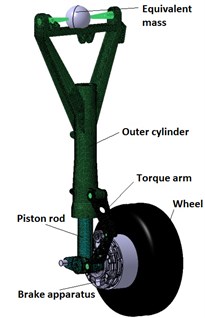
The rigid-flexible coupling dynamic model of the half-axle main landing gear shown in Figure1 is built in LMS Virtual.Lab Motion based on some data of some type of airplane. The flexibility of the piston rod, the outer cylinder and the torque arm is considered in the model.
Fig. 1Rigid-flexible coupling multi-body model of the half-axle main landing gear. The piston rod, the outer cylinder and the torque arm are flexible bodies; the equivalent mass, the wheel axle and the brake apparatus are rigid bodies. The tire model is based on Pacejka tire model, see Section 2.2
2.2. Tire model
The tire model used in this study is based on classic Pacejka Magic-Formula tire model [15], the magic formula is:
where can either be lateral force, aligning torque or longitudinal force, the independent variable can be sideslip angle or slip rate, the coefficients , , can be determined by vertical load and camber angle.
The tire deflection is calculated by [17]:
where is the deflection caused by the tire vertical force, is the tire vertical force, is the actual tire inflation pressure, is the rated tire inflation pressure, is the tire sectional width, and is the tire diameter, respectively.
The corresponding tire internal pressure is given by [18]:
Slip rate is a parameter used to measure the brake level of a tire. It is defined as the amount of the tire skidding relative to the ground. The slip rate is defined as:
where is the forward taxiing speed, is the linear velocity of the tire.
During the braking process, the friction coefficient [16] between the tire and the ground is computed according to the slip rate, namely:
– Dry runway:
– Wet runway:
– Icy runway:
The rotation of the wheel is caused by the friction torque and by the braking torque :
where and are the angular velocity and the angular acceleration, is the rotational inertia of a wheel, is the rolling radius, respectively.
The friction torque can be calculated by:
where is the friction coefficient between the tire and the ground, is the frictional force between the tire and the ground, and is the bearing reaction force of the tire.
2.3. Shock absorber model
The shock absorber of the half-axle main landing gear is a single-cavity oleo-pneumatic shock absorber. The buffer axle force consists of air spring force , oil damping force and structure restriction force [16]. The expression of the buffer axle force is:
Without regard to the compressibility of hydraulic oil and the change of cavity volume, the air spring force can be calculated by:
where is the cross section area of the air cavity, is the original additive gas pressure, is the air polytropic exponent, and is the atmospheric pressure.
Assume that the oil hole area of the main oil cylinder cavity remains the same and there exists a side oil hole, then the oil damping force can be computed as:
where is the oil density, is the effective cross section area of the main oil cavity, is the oil hole area of the main oil cavity, is the contraction coefficient of the main oil cavity, is the effective cross section area of the return oil cavity, is the oil hole area of the return oil cavity, and is the contraction coefficient of the return oil cavity, respectively.
The structure restriction force is given by:
where is the structure restriction stiffness, and is the compression stroke of the shock absorber.
2.4. Fundamental dynamic model verification
2.4.1. Comparison of dynamic simulation with experiment results
The simulation of the tire static curve, the landing gear drop test and the first order longitudinal mode of the rigid-flexible coupling model is carried out based on the landing gear dynamic model. Simulating results are compared to the corresponding experimental data. The comparisons are shown in Fig. 2, Fig. 3 and Table 1.
Table 1Comparison of simulation and test of the main landing gear first order longitudinal mode
Buffer stroke / mm | 0 | 100 | 250 |
Simulation / Hz | 78.13 | 85.24 | 92.07 |
Test / Hz | 72 | 79 | 88 |
Error / % | 8.5 | 7.9 | 4.6 |
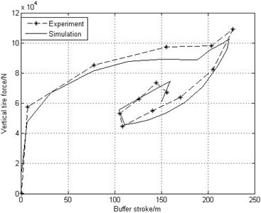
From Fig. 2 it is seen that the simulation of the tire static curve agrees well with the experiment results. Comparisons of the drop dynamic figure of the main landing gear drop test shown in Fig. 3 and the main landing gear first order longitudinal mode listed in Table 1 show that the simulation of the drop test is similar to the experiment data and the error of the first order longitudinal mode between the simulation and the experiment results is within 10 %. Therefore, the established rigid-flexible dynamic model is correct and effective.
Fig. 2Tire static curves of simulation and experiment
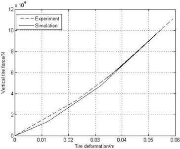
Fig. 3Drop dynamic figure of main landing gear drop test and simulation
2.4.2. Verification of the gear walk dynamic model during landing
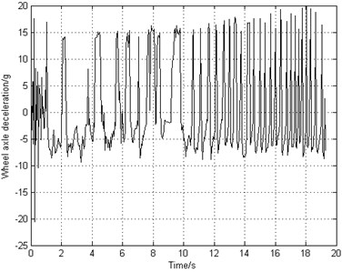
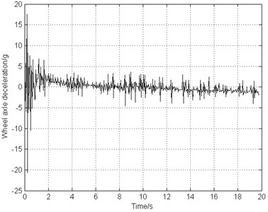
When the tire just touches the ground before the braking system starts working, the rotational speed of the wheel accelerates from stationary state to pure rolling state. During this landing process, the fore and aft vibration of the landing gear strut occurs. According to the test data and relevant information in literature [11], at the moment when the tire touches the ground, the peak value of landing gear longitudinal acceleration can reach from ±15 g to ±30 g. Fig. 4 illustrates that the wheel axle longitudinal acceleration is approximately ±20 g, consistent with the test results. Therefore, the brake-induced vibration model is verified and fitted well with the dynamic characteristic of the actual landing gear, thus can be used to investigate the gear walk.
Although the peak value of landing gear longitudinal acceleration reaches 20 g at the moment when the landing gear touches the ground, such a high acceleration of the wheel axle will produce unstable longitudinal vibration during braking process. As a result, a braking system with an appropriate braking torque is necessary to reduce the phenomenon of the gear walk.
Fig. 4Wheel axle acceleration-time diagram after the tire touching the ground
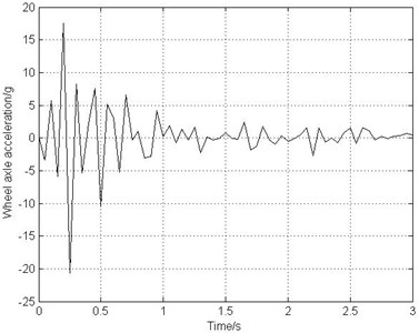
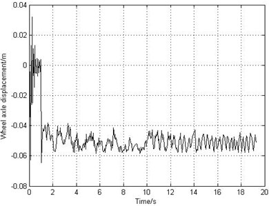
Fig. 5Wheel axle displacement-time diagram after the tire touching the ground
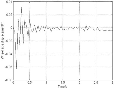
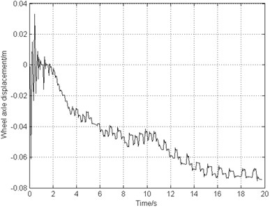
Fig. 5 shows that the initial longitudinal displacement of the wheel axle reaches maximum values ranging from –0.06 m to +0.03 m. Then the amplitude decays rapidly to around zero. After 1 second of landing, the landing gear and the rotating wheel come to a steady state and then the braking system starts to work.
3. Deceleration brake
3.1. Deceleration braking control system modeling
The original braking control system of this type of airplane is deceleration braking control. This braking control law is simple to design and easy to take into practice. However, it is of low braking efficiency [17] and would lead to severe gear walk. The deceleration braking control theory is that the braking system detects the forward velocity through the velocity sensor and calculates the deceleration of the airplane, then the braking system outputs braking torque. When the deceleration is lower than 5 m/s², the braking system starts to output braking torque of 10000 N∙m to the rotating wheel, while the deceleration is higher than 5 m/s², the braking system stops working. The expression of the braking control law is given below:
where is the braking torque.
This braking control system model is established in MATLAB/Simulink, is joint-simulated with the dynamic model presented in Section 2 to study the vibration performance of the gear walk.
3.2. Simulation results and discussion
The deceleration braking control system starts to work after 1 second of landing. The landing operating condition is that the runway is dry and smooth. The landing forward velocity is 77 m/s. The equivalent longitudinal stiffness of the landing gear strut is 1.04e6 N/m. The frictional coefficient between the brake disks is 0.25. Fig. 6(a) shows that the airplane can stop completely in 20 s and the airplane brakes with a constant deceleration. However, Fig. 6(b) indicates that the rotating speed of the braking wheel shocks with poor stability and in high frequency. Fig. 6(c) shows that the slip rate fluctuates around 0.05 rather than the optimal value 0.15 so that the frictional coefficient and the frictional force are relatively small, resulting in low braking efficiency. Fig. 6(d) and Fig. 6(e) illustrate that the fluctuating frequency of braking torque is very high which leads to high vibrating frequency of gear walk. As time goes on, the braking torque adjusts more frequently and the phenomenon of brake-induced vibration becomes more serious. Fig. 6(f) shows that the longitudinal acceleration of the wheel axle increases gradually and the amplitude value reaches 20 g. As mentioned previously in Section 2.4.2, the vibration becomes unstable when the longitudinal acceleration reaches 20 g. That will not only shorten the fatigue life of landing gear, but also cause severe accidents.
4. PBM reference speed-speed difference brake
4.1. Reference speed-speed difference braking control system with PBM (Pressure-Bias-Modulated) control system modeling [16]
4.1.1. PBM reference speed-speed difference braking control law
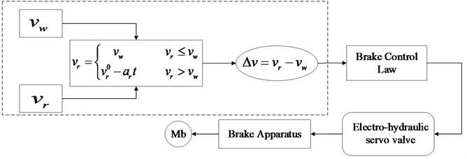
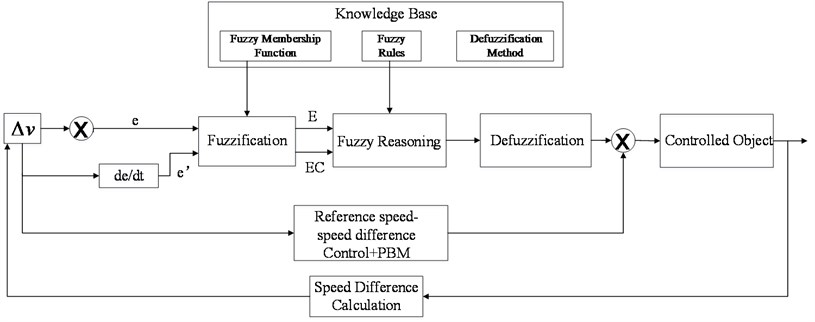
This type of braking control law is similar to the classic PID control. The difference is that in order to obtain better braking performance, the integration coefficient of this controller is variable due to the input. The input of the reference speed-speed difference braking control system with PBM is quasi slip velocity. Slip velocity is the difference between the airplane forward velocity and the linear velocity of the braking wheel. The control system replaces the airplane forward velocity with the reference speed and then the quasi slip velocity can be figured out. This type of control law is of more accurate control and better stability since detecting the actual airplane forward velocity is not necessary. The diagram of this control theory is shown in Fig. 7.
Fig. 6Simulation results of deceleration-rate braking system
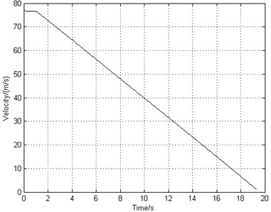
a) Aircraft speed
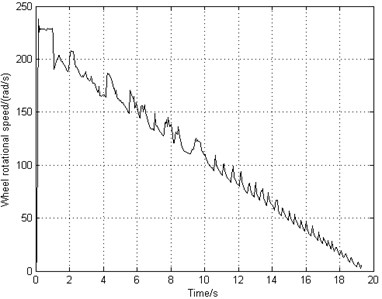
b) Wheel speed
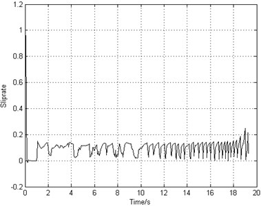
c) Slip rate
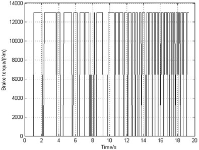
d) Brake torque
e) Longitudinal displacement of wheel axle
f) Longitudinal acceleration of axle wheel
The reference speed-speed difference braking control box with PBM contains not only the speed input and the reference speed calculation module in the dashed box in Fig. 7, but also the comparator and PBM modules. The control process is that the reference speed is calculated by the reference deceleration and the linear velocity of the braking wheel, then the wheel linear velocity and the reference speed are compared and amplified. The comparator output is the input of PBM module. The desired control effect is to make the wheel linear velocity tend to converge to the reference speed. And the output of this PBM module is the input of the brake apparatus.
Fig. 7Diagram of the reference speed-speed difference braking control theory
4.1.1.1. Reference speed module
The following control law should be obeyed. If the wheel linear velocity is higher than the reference speed, the reference speed is then equal to the wheel linear velocity, otherwise the reference speed decreases according to a constant reference deceleration. The reference speed is computed by:
where is the reference speed, is the wheel linear velocity, is the reference speed of the previous instantaneous moment, and is the reference deceleration, respectively.
If the wheel linear velocity is higher than the reference speed, it means that the braking torque is insufficient. Then the reference speed is equal to the wheel linear velocity so that the anti-skid electric current is about zero which enlarges the braking torque to the peak value. On the contrary, the braking torque will decrease to release the excessive brake.
The value of deceleration has great influence on braking system. If the deceleration is too large, the control system would response slowly. If the deceleration is too small, the system would encounter high frequency oscillations.
4.1.1.2. Comparator
The difference between the reference speed and the wheel linear velocity is amplified and output to the next module. The expression is:
where is the output voltage of the comparator, is the proportional gain.
4.1.1.3. Proportion and differentiation modules
The proportion module is the proportional cycle amplifying the output of the comparator:
where is the proportional coefficient.
The differentiation module is:
where is the differential coefficient.
4.1.1.4. PBM module
The control theory of PBM is to settle different threshold values and different control parameters according to the input value. If the input, the difference between the reference speed and the wheel linear velocity, is higher than a certain threshold value, it means that the braking torque is too high and a bigger control parameter is needed to reduce the braking torque sharply. If the input value is lower than that threshold value, then a smaller control parameter is needed to decrease the braking torque gently. If the input value is close to zero, another control parameter is needed to increase the braking torque to improve the braking efficiency. The output voltage of PBM module is defined as:
where , and are the voltage values of the last instantaneous moment, and are the threshold values, and are the control parameters.
4.1.2. Hydraulic braking apparatus modeling
The output of the electro-hydraulic servo valve is the brake pressure, controlled preciously by the input current to realize the braking function. The output pressure is in inverse proportion to the input current.
When modeling the electro-hydraulic servo valve, a second order transfer function is adopted to represent the electro-hydraulic servo valve model:
where is the proportionality coefficient of the electro-hydraulic servo valve, is the damping of the electro-hydraulic servo valve, is the natural frequency of the electro-hydraulic servo valve.
Also the frictional loss and time delay of the oil pipelines should be considered. A first order transfer function is used:
where is the proportionality coefficient of the pipeline inertia unit, is the retardation coefficient of the pipeline.
Then function of the output brake pressure and the input current is:
where is the output brake pressure of the electro-hydraulic servo valve, is the input current, and are the linear function coefficients.
Due to that there is a return spring and small distance between brake stators and rotors in the disk type brake apparatus, the relationship between braking torque and brake pressure is:
where is the friction coefficient between the brake stators and rotors, is the number of the friction contact surfaces, is the outer radius of the brake stators, is the inner radius of the brake rotors, is the pressure loss generated by the return spring and small distance between brake disks.
4.2. Simulation results and discussion
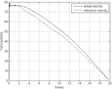
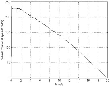
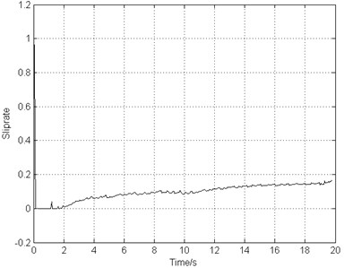
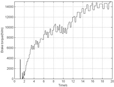
The landing operating condition is the same as the one used in Section 3.2. Fig. 8(a) indicates that the airplane stops in 20 s smoothly, remaining the same braking time comparing to the deceleration brake, while Fig. 8(b) illustrates that the rotating speed of the braking wheel shocks markedly slightly. As can be seen from Fig. 8(c) that the slip rate keeps increasing during the whole taxiing process even though the value ranging from 0.1 to 0.2, the braking efficiency is not high either. Fig. 8(d) show that of the braking torque frequency drops by about 25 % and the torque amplitude fluctuates much more mildly in comparison with the deceleration brake. Fig. 8(e) demonstrates the high vibrating frequency of gear walk resulting from high frequency braking torque and the vibration amplitude growing gradually when braking, but still smaller vibration amplitude and lower frequency comparing to the deceleration brake. Fig. 8(f) shows that after 2 seconds, the longitudinal acceleration of the wheel axle remains under 5 g, acceptable according to the data in reference [11].
5. Combined brake
5.1. Combined braking control system designing and modeling
To solve the problems of the severe gear walk caused by both the deceleration and only PBM braking control laws, a new braking control law is promoted and designed for this type of airplane. The control law combines reference speed-speed difference braking control with fuzzy control [19] to replace the original deceleration control law on the half-axle landing gear to stop the airplane.
The reference speed-speed difference braking control system is the same as Section 4. Due to the complexity and nonlinearity of braking system, the braking process would be inefficient and the robustness would be weak if there is only the PBM control is used in the braking system. Therefore, adding fuzzy control into the braking system would be necessary and would improve the braking performance. The fuzzy control law is designed and the fuzzy control rule is obtained based on test data and expertise to ensure that the braking system can restrain gear walk effectively.
The structural schematic diagram of anti-skid braking control system is shown in Fig. 9. The controller is a single variable two-dimensional Mamdani controller. One of the inputs of fuzzy controller is the same as the input of the reference speed-speed difference controller, namely, the difference between the reference speed and the wheel linear velocity . The other input is its derivative . The output voltage of the fuzzy controller is the input of the brake apparatus. This kind of two-dimensional controller can reflect the dynamic behavior of the system and improve the braking control performance.
Fig. 8Simulation results of PID antiskid braking system
a) Aircraft speed
b) Wheel speed
c) Slip rate
d) Brake torque
e) Longitudinal displacement of wheel axle
f) Longitudinal acceleration of axle wheel
5.1.1. Identifying inputs and outputs
The inputs and outputs are fuzzified and the fuzzy domains can be divided into 7 sets:
The difference between the reference speed and the wheel linear velocity is:
The derivative of the velocity difference is:
Fig. 9The structural schematic diagram of anti-skid braking control system
The output voltage is:
The membership functions of every fuzzy set should be determined. In order to guarantee both the sensitivity and the robustness, selecting the membership functions needs several times of modification and is shown in Fig. 10. The membership functions of the two inputs are Gaussian-type, while the output is triangular type.
Fig. 10The fuzzy sets and the membership functions of variables
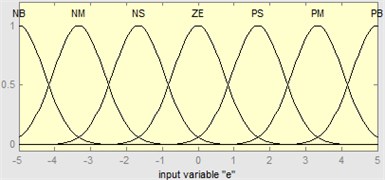
a) The fuzzy sets and the membership functions of input
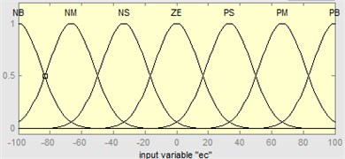
b) The fuzzy sets and the membership functions of input
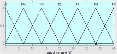
c) The fuzzy sets and the membership functions of output
5.1.2. Fuzzy rules
In Mamdani fuzzy controller, the fuzzy control rule is equivalent to the classic PID control. The fuzzy control rule of this braking system is shown in Table 2. Mamdani minimum computation method is adopted to run fuzzy logic operations.
5.1.3. Defuzzification
The last step of fuzzy control is to transform the fuzzy sets to an exact physical value. The method of Center of Area is used here to obtain the output voltage. If the domain is , the membership function of the fuzzy set is , . If the -coordinate of the center of area is , then is calculated as:
Table 2Fuzzy control rules
NB | NM | NS | ZE | PS | PM | PB | |
NB | NB | NB | PS | ||||
NM | NS | NM | NM | PS | PS | ||
NS | NM | NM | NS | NS | ZE | PM | PM |
ZE | NB | NM | NS | ZE | PS | PM | PB |
PS | NM | NM | ZE | PS | PS | PM | PM |
PM | NS | NS | PM | PM | PS | ||
PB | NS | PB | PB | ||||
5.2. Simulation results and discussion
The landing operating condition is the same as the one used in Sections 3.2 and 4.2. The combined braking system starts to work after 1 second of landing. From Fig. 11(a) and Fig. 11(b), it can be seen that the airplane stops in 16 s, decreased by about 17 % comparing to the deceleration brake. The airplane keeps stable taxiing in a constant deceleration and the wheel rotating speed reduces steadily. Fig. 11(c) illustrates that the slip rate is close to the optimal value 0.15. This indicates that the frictional force between the ground and the tire reaches the maximum, bringing about higher braking efficiency. Fig. 11(d) shows that the braking frequency is very low ranging from 1 Hz to 2 Hz. Fig. 11(e) indicates that the vibration frequency approximately equals to the braking frequency and the gear walk average amplitude is only 2 mm. Fig. 11(f) demonstrates that the wheel axle longitudinal acceleration is located at 5 g. As time goes on, the acceleration decreases smoothly and the gear walk phenomenon converges in a stable state.
5.3. Comparison of the influence of two braking systems on gear walk
The modified combined brake and PBM reference speed-speed difference brake simulation results, related to gear walk characteristics are compared to the results of original deceleration brake in Table 3.
Table 3Percentage change of two proposed brake simulation results relative to deceleration brake
Change of wheel axle gear walk average amplitude (%) | Change of wheel axle longitudinal acceleration peak value (%) | Change of braking time (%) | Change of braking frequency (%) | Change of gear walk frequency (%) | |
Only PBM brake | –26.53 % | –65.76 % | +1.28 % | –25 % | –31.81 % |
Combined brake | –73.16 % | –91.04 % | –17.09 % | –50 % | –59.02 % |
From Table 3, it can be seen that in the same landing and taxiing operating condition, the average wheel axle gear walk average amplitude decreases by 73 % under the control system of combined brake, and the only PBM brake system by 26 %. Meanwhile, the average wheel axle longitudinal acceleration peak value reduces by 65 % and 91 % respectively. In addition, the braking time is shortened by 17 % of combined system and the PBM system almost remains the same. This indicates that not only the braking efficiency is improved but also the braking frequency drops sharply by the new combined system, much better than the improvement of the only PBM system. The modified braking system works more steadily and is able to protect the braking apparatus. Due to lower braking frequency, the vibration frequency of gear walk also decreases by 59 %, making the vibration gentler. Therefore, the gear walk phenomenon is weakened effectively by the modified combined braking control system.
Fig. 11Simulation results of combined braking system
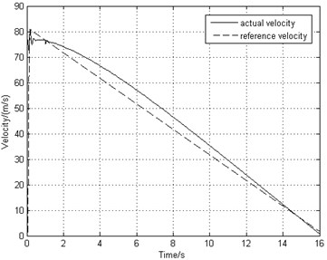
a) Aircraft speed
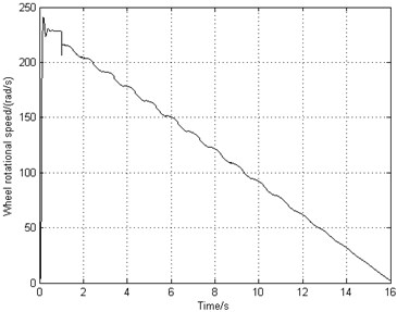
b) Wheel speed
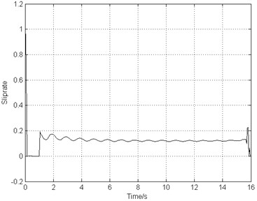
c) Slip rate
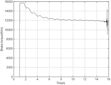
d) Brake torque
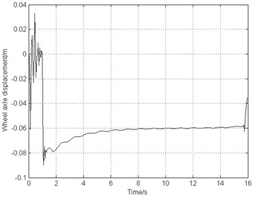
e) Longitudinal displacement of wheel axle
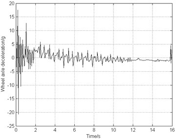
f) Longitudinal acceleration of axle wheel
6. The stability and robustness of the combined braking control system
6.1. Runway surface
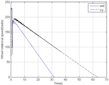
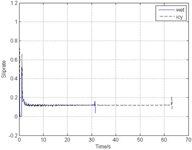
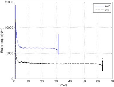
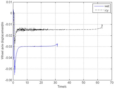
Due to different weather change, the runway would become wet or icy, leading to the drop of the friction coefficient between the ground and the tire. The friction coefficient value varies according to Eq. (5). Fig. 12 shows the simulation results of the braking response and gear walk performance when the runway surface is wet and icy, with other operating conditions remaining unchanged.
Fig. 12Simulation results of different runway surfaces
a) Wheel speed
b) Slip rate
c) Brake torque
d) Longitudinal displacement of wheel axle
As can be seen in Fig. 12(a), the aircraft could stop in 32 s and 63 s on wet and icy runway respectively. With the decrease of the friction coefficient of the runway as the largest coefficient drops from 0.8 to 0.4 and 0.2, the braking time multiples. However, Fig. 12(b) shows that even though a step response appears at the start of braking and there is some fluctuation during the first half of the whole process, the wheel velocity, the braking torque and gear walk vibration converge to a constant and the vibration is gentle. Fig. 12(c) and Fig. 12(d) illustrate that on the icy runway, the main landing gear vibrates a little more fiercely than it on the wet and dry runway with a higher gear walk frequency, while the vibration and the brake torque amplitudes are both lower due to the smaller friction force on the ground. A large span of the friction coefficient variation indicates that the proposed combined braking control system performs well and is of good adaptability.
6.2. Landing gear strut longitudinal stiffness
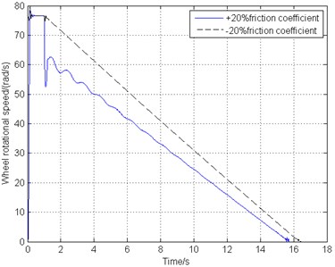
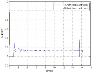
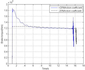
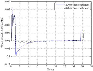
Gear walk, caused by several external and internal factors, is a longitudinal vibration on the landing gear. Therefore, the longitudinal stiffness of the main landing gear strut is one of the most important internal factors and has great impact on gear walk. Fig. 13 demonstrates the braking response and gear walk performance under different strut longitudinal stiffness ranging from –20 % to +20% change of the original structure stiffness.
Fig. 13Simulation results of different landing gear strut longitudinal stiffness
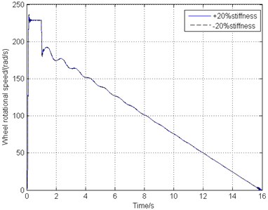
a) Wheel speed
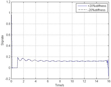
b) Slip rate
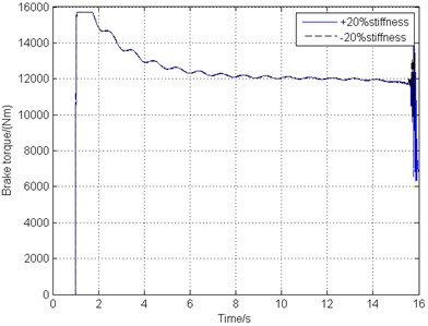
c) Brake torque
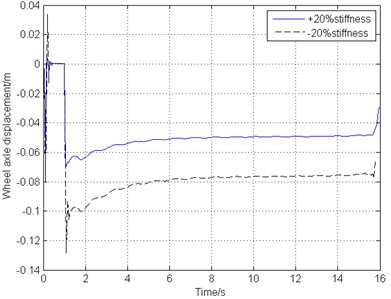
d) Longitudinal displacement of wheel axle
From Fig. 13, it can be seen that the internal factors variation such as the landing gear strut longitudinal stiffness does not have any influence on the brake response. Fig. 13(a), (b), (c) indicate that the combined braking control law is also stable in this landing gear system no matter how the landing gear strut structure changes. Fig. 13(d) shows that as the decreasing of the strut longitudinal stiffness, gear walk amplitude becomes larger, but the vibration frequency and trend stay the same.
6.3. Brake disks friction coefficient
Brake apparatus is also one of the most significant part in braking system, working together with braking control laws to stop the aircraft within the required time and distance safely. Possible fluctuant hydraulic pressure and worn-down with use of the brake disks would take place during the braking process, requiring the braking control system’s good robustness to ensure the aircraft security. Fig. 14 shows the simulation results under ±20 % friction coefficient variation between the brake disks contact surfaces.
Different friction coefficient between brake disks results in different braking torque under the control system output. Fig. 14 shows that larger brake torque lead to shorter braking time but a little fiercer fluctuation of the tire, braking torque and gear walk vibration at the first half section of the whole process. However, after the adjustment of the braking control law, the gear walk tends to vibrate gently and remain smooth, indicating that this combined control law possesses good stability and robustness.
Fig. 14Simulation results of different brake disks friction coefficient
a) Wheel speed
b) Slip rate
c) Brake torque
d) Longitudinal displacement of wheel axle
7. Conclusions
The main research and conclusions are summarized as follows:
1) A rigid-flexible coupling dynamic model of a half-axle main landing gear is built based on some type of airplane and the fundamental dynamic model is verified by comparing to the experiment data. The results indicate that the rigid-flexible dynamic model is correct and effective, and can be used to do research further on the gear walk.
2) The original deceleration braking control system is established in MATLAB/Simulink. The dynamic model in LMS Virtual.Lab Motion and the control model in MATLAB/Simulink are co-simulated to study gear walk performance. The simulations show that under this kind of braking control system, the braking torque fluctuates frequently leading to violent gear walk. The peak value of the wheel axle longitudinal acceleration reaches 20 g resulting unstable brake-induced vibration and may have great impact on both structural strength of the landing gear and the brake apparatus.
3) A deterministic brake control law, PBM reference speed-speed difference brake, is adopted to try to improve the braking and gear walk vibration performance of the landing gear. However, even though the average wheel axle gear walk amplitude decreases by 26 %, the average wheel axle longitudinal acceleration peak value by 65 % and the braking and gear walk frequency reduces about 30 %, the braking efficiency is not improved and the gear walk vibration is not as stable as the combined brake system.
4) To solve the problems of the severe gear walk caused by the deceleration braking control law, a modified braking control law combining the reference speed-speed difference (with PBM) control with the fuzzy control is designed. The simulations and the comparisons of the two braking laws demonstrate that the modified braking control law can weaken the gear walk considerably. The braking frequency increases by 17 %. The average wheel axle gear walk average amplitude decreases by 73 % and the longitudinal acceleration drops by 91 %. The braking frequency decreases by 50 % so that the vibration frequency of gear walk decreases by 59 %.
5) The combined braking control law is of great stability, adaptability and robustness under variable external conditions. Some external factors such as runway and brake apparatus variation will have impact both on brake response and gear walk, while the internal factors such as landing gear structure change only have influence on gear walk performance.
References
-
Li Yuren, Zhang Zhihui, Xu Jianglong Study on fuzzy sliding-mode variable structure control for aircraft anti-skid braking. Journal of Northwestern Polytechnical University, Vol. 33, Issue 1, 2015, p. 45-49.
-
Feng Fei, Chang Zheng, Nie Hong, Zhang Ming, Peng Yiming Analysis of influence of aircraft flexibility on nose landing gear shimmy. Acta Aeronautics et Astronautica Sinica, Vol. 32, Issue 12, 2011, p. 2227-2235.
-
Wang Hongling, Tian Guanglai, Fu Longfei, Liu Jingsong, Qiang Gang, Zhao Wenqing Study on resonance of braking pressure control system of multi-wheel and multi-strut aircraft. Journal of Northwestern Polytechnical University, Vol. 32, Issue 4, 2014, p. 646-650.
-
William S. Chao Brake Hydraulic System Resonance Analysis. American Institute of Aeronautics and Astronautics, Inc., 1997.
-
Chevillot F., Sinou J.-J., Mazet G. B., Hardouin N., Jezequel L. The destabilization paradox applied to friction-induced vibrations in an aircraft braking system. Archive of Applied Mechanics, Vol. 78, 2008, p. 949-963.
-
Khapane P. D. Gear walk instability studies using flexible multibody dynamics simulation methods in SIMPACK. Aerospace Science and Technology, Vol. 10, 2006, p. 19-25.
-
Pritchard J. An Overview of Landing Gear Dynamics. NASA/TM-1999-209143, Virginia, 1999, p. 1-20.
-
Zhang Ling, Zhu Depei On the dynamic properties of landing gear walking. Acta Aeronautica et Astronautica Sinica, Vol. 17, Issue 3, 1996, p. 292-296.
-
Ku Yuao Interaction between braking landing gear vibration. Acta Aeronautica et Astronautica Sinica, Vol. 18, Issue 2, 1996, p. 228-230.
-
Li Feng, Liu Gang, Zhang Yu A simulation research on proper design of aircraft antiskid braking system considering avoidance of gear walk. Journal of Northwestern Polytechnical University, Vol. 17, Issue 3, 1999, p. 404-408.
-
Gualdi S., Morandini M., Ghiringhelli G. L. Anti-skid induced aircraft landing gear instability. Aerospace Science and Technology, Vol. 12, 2008, p. 627-637.
-
Wu Huawei, Chen Tefang, Hu Chunkai, Ku Yuao Simulation of the resonance caused by aircraft braking. Aviation Precision Manufacturing Technology, Vol. 48, Issue 2, 2012, p. 50-53.
-
Wei Xiaohui, Yin Qiaozhi, Nie Hong, Zhang Ming, Tao Zhouliang Aircraft electric anti-skid braking system based on fuzzy-PID controller with parameter self-adjustment feature. Transactions of Nanjing University of Aeronautics and Astronautics, Vol. 31, Issue 1, 2014, p. 111-118.
-
Wei Xiaohui, Liu Chenglong, Liu Xiangyao, Nie Hong, Shao Yizhou Improved model of landing-gear drop dynamic. Journal of Aircraft, Vol. 51, Issue 2, 2014, p. 695-700.
-
Wang Jisen Nonlinear Control Theory and Its Application to Aircraft Antiskid Brake Systems. Northwestern Polytechnical University, Xi’an, 2001.
-
Zhang Ming Research on Some Key Technologies of Aircraft Ground Dynamics. Nanjing University of Aeronautics and Astronautics, Nanjing, 2009, p. 23-24.
-
Aircraft Design Manual: Taking Off and Landing System Design. Aviation Industry Press, Beijing, 2002.
-
Zhu Depei Shimmy Theory and Anti-Shimmy Measure. National Defense Industry Press, Beijing, 1984.
-
Shi Xinmin, Hao Zhengqing Fuzzy Control and MATLAB Simulation. Tsinghua University Press, Beijing, 2008, p. 93-113.
Cited by
About this article

This study was funded by the National Natural Science Foundation of China (Grant No. 51305198), the Research Fund of State Key Laboratory of Mechanics and Control of Mechanical Structures (Nanjing University of Aeronautics and Astronautics) (Grant No. 0214G01), Funding of Jiangsu Innovation Program for Graduate Education (KYLX_0297 and KYLX15_0240), Specialized Research Fund for the Doctoral Program of Higher Education (Grant No. 20123218120003), the Fundamental Research Funds for the Central Universities, the Priority Academic Program Development of Jiangsu Higher Education Institutions.
Qiaozhi Yin builds the dynamic gear walk model and the braking control systems and is responsible for writing the paper. Hong Nie gives an instruction on the outline of the paper and provides some revising suggestions on this paper. Ming Zhang conducts the landing gear drop tests and helps to revise the manuscript. Yongquan Wang carries on the static experiments of the main landing gear and helps to give some analysis on the simulation results. Jian Deng builds the finite element (FE) analytical model of the main landing gear and helps to polish the writing language of the manuscript.
