Abstract
In the very early the problem of train induced ground vibrations has received considerable attention, due to the sever effect of wheel-rail interaction force on the railway infrastructures and nearby buildings. To predicate and mitigate such vibration problems, three dimensional finite element packages are most recently and widely used numerical method, although method of achieving non-reflecting boundary condition to avoid the boundary-related wave reflection is still problem. In most case, wide finite element models far from the field that is capable of minimizing the reflection is favored by researchers. However, modelling wide finite element mesh is time consuming and it is the most difficult issue to determine whether the cross-sectional model is sufficient. Thus, other schemes such as the material property of the non-reflecting soil model have to incorporate to minimize the size in the cross-sectional directions. Hence, a parametric study by using ABAQUS is conducted in this paper to identify the paramount important parameters of the soil that may affect the boundary-related wave reflection caused by the moving train loads. With this perspective, the finite element model is divided into two regions, called the near-field and far-field. The near-field includes the moving train loads and other geometric/material properties of the entire railway infrastructure represented by the finite element, while the far-field is covered the non-reflecting model placed at the truncated boundaries. To this end, a systematic study is carried out to examine the sensitivity of damping ratio, length, Young’s modulus and Poisson’s ratio of the boundary in suppressing the reflections. The results demonstrate the beneficial role of the boundaries and their parameters in suppressing the reflection, if the paramount important parameters are properly selected.
Highlights
- 3-D finite element model consists of the railway track components is created using Abaqus.
- A non-reflecting boundary is modeled at the truncated boundaries to absorb the reflection.
- A parametric study on the boundary is performed to study their effects in screening of the reflection.
- Abaqus/explicit analysis was used to analyze the ground borne vibrations.
- The study has been proven the importance of defining of the non-reflecting boundary attached to the end of the original model.
1. Introduction
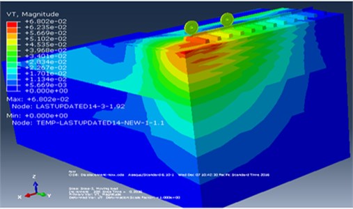
Railways are a solution to traffic congestion and pollution; however one drawback is the problem of noise and vibration [1]. To predicate and mitigate such vibration problems, finite element models of train induced ground vibrations has been increasingly contributed in recent years, since full scale model test results are often difficult to extrapolate [2]. However, the finite element model must be terminated at finite boundary and appropriate assumptions about the boundary condition to be applied must be made. In train-induced-ground vibration analysis, as it has been demonstrated in Fig. 1, waves can be bounced back from the borders and superimpose with the progressing waves, when the finite portion of the ground model is not sufficient to avoid the spurious reflections of waves caused by the dynamic loading. To overcome these problems, many previously published papers have used two different methods. Train-Induced Wave Propagation in layered soils using Finite/Infinite Element is simulated in [3] and used to study the transmission of train-induced ground vibration moving at different train speeds. In this study, the effect of different parameters (i.e., shear wave speed, damping ratio, stratum depth of the supporting soils, moving speed and vibration frequency of the traveling trains) on the ground response are conducted. This work have made a great contribution to concluding the mechanism of wave propagation in layered soils, and the infinite elements are used to minimize the influence of the modeled domain boundaries.
A infinite element was also used in numerical modelling of ground borne vibrations from high speed rail lines on embankments [4] in which train-track-ground interface model was interpreted in Abaqus. The study used to investigate the effect of embankment constituent material on ground borne vibration levels at various distances from the track. To increase the absorption performance of the absorbing boundary (infinite element), the soil structure is modeled using an elongated spherical geometry. Similarly, a number of authors, e.g. [5-13], have used infinite elements combined with finite element models to determine the dynamic response of the train-track-ground models, due to its simplicity and ease to combine with the finite elements. However, it has been shown in [14-16] that use of infinite element is not satisfactory. In this regard, [17-23] established geometrically wide cross-sectional model far from the moving train loads, that can avoided the boundary-related wave reflection problems by spreading the vibration energy over large area. However, modelling wide finite element mesh is computationally expansive depending on the model being analyzed and suffers from the drawback that the geometric radiation effect of the half space is the most difficult issue to model properly. Hence, in [24-26] finite element models for the analysis of more comprehensive response of railway line under moving train loads were presented. To avoid any spurious reflections generated by the finite boundary of the finite element model damped artificial non-reflecting boundary was designed using frequency domain analysis and absorbing regions.
Although the above finite element models have made a great effort on solving the dynamic response of track-subgrade system and vibration transmission to buildings near the railway lines, the effect of different parameters of the artificial non-reflecting boundary (i.e., damping ratio, Young’s modulus, Poisson’s ratio, and length) on avoiding any spurious reflection are still remains. To fill such a gap, parametric study is conducted in this paper to identify the paramount important parameters that may affect the boundary-related wave reflection caused by the moving train loads. With this perspective, the finite element model is divided into two regions, i.e., the original model and far field, as shown in Fig. 5. The near field, including the moving train loads and other geometric/material properties of the entire railway infrastructures represented by finite elements, while the far field is covered the non-reflecting boundary located at the truncated boundaries.
.
Fig. 1Visualization of wave reflection in the original model by Abaqus/CAE
2. Finite element formulation in Abaqus
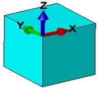
All the components of the track were represented using eight-node linear brick elements as shown in Fig. 2. The global coordinates (, and ) and local coordinates (, and ) are regarded as a variant of the 8-node linear brick elements. The displacement of the element which is a function of coordinates , and is interpolated by:
where:
is the nodal displacement in which:
is the displacement at node and the shape function matrix is given by:
in which each sub-matrix, is given as:
Fig. 2Eight-node linear brick element
The shape functions, take on the usual form in terms of local coordinates, , and , as:
where denotes coordinates of node .
Rayleigh damping model is considered in the formulation to represent the material damping of the railway components. In every node of the mesh, the damping matrix [] is directly proportional to the mass matrix [] and stiffness matrix [] given by:
where and are the Rayleigh damping factors required to solve the dynamic problems:
From Eq. (8), it can be observed that the damping ratio is proportional to the circular frequency and Rayleigh damping factors, and of the system. Considering the frequency range of interest ( and ) and their damping ratio values of the vibrational modes th and th, the method of determining the Rayleigh damping coefficient as is shown in Eq. (9) and Eq. (10) was used. These Rayleigh factors can be defined in Abaqus/property module. However, modal analysis should be performed, in order to obtain the main vibration modes and these pre-defined constant. Therefore, Abaqus frequency analysis has been used to calculate the natural frequencies and corresponding mode shapes of the model. The model system has many degrees of freedoms and therefore many modes, but for most practical problems the lowest frequencies are the most important and 30 mode shapes were used to represent the dynamic behavior of the track. The total modal effective mass for all of these modes was well over 90 % of the mass of the track that can move in the -direction, indicating that the dynamic representation is adequate and the table of participation factor indicated that the railway track starts vibrating predominately in the vertical direction. An example of mode shapes (1st and 30th) and Eigen values extracted for the base set parameters shown in Table 2 and Table 3 is reported in Fig. 3.
Fig. 3Railway track mode shapes at: a) 3.65 Hz and b) 9.44 Hz
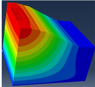
a)
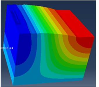
b)
3. 3-D FE model
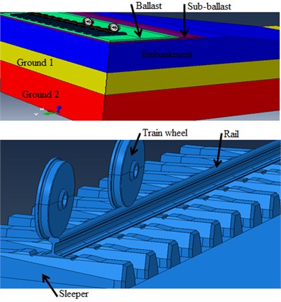
A compressive model comprises of rail (UIC-54), rail-pads, sleepers and the soil layers are modeled as 3-D solid finite element model in Abaqus with geometry aspects shown in Fig. 4. The mass of rail-pads is neglected and considered as spring and dashpot, since the rail-pads mass is negligible with respect to concrete sleeper’s mass, while comparing mass and stiffness between rail-pads and concrete sleepers. The finite element model was developed by considering rolling and translating a series of successive moving wheel loads in finite length of a railway track at the speed of 120 km/h. Further, to reduce excessive computational burden, it was decided to solve the 3-D dynamic problem through symmetry with respect to the center line. Three kinds of soil profiles are considered in this study (i.e., Ground 2, Ground 1 and Embankment). The elastic properties of the train wheels, superstructure, substructure and the ground layers are shown in Table 2 and Table 3.
Table 1Principal infrastructures of the model
Infrastructure | Thickness (m) |
Ballast | 0.15 |
Sub-ballast | 0.15 |
Embankment | 2.5 |
Ground 1 | 2 |
Ground 2 | 11.5 m |
Table 2The material properties of train wheel, superstructure and substructure
Elastic characteristic | Wheel | Rail | Sleeper | Ballast | Sub-ballast |
Density (kg/m3) | 7800 | 7800 | 2400 | 1600 | 1900 |
Modulus (MPa) | 210000 | 210000 | 37278 | 150 | 80 |
Poisson’s ratio | 0.3 | 0.3 | 0.2 | 0.35 | 0.35 |
Table 3The material properties of sub-grade and subsoil layers
Infrastructure (Soil layers) | Density (kg/m3) | Modulus (MPa) | Poisson’s ratio | Damping ratio (%) |
Embankment | 1600 | 50 | 0.3 | 5 |
Ground 1 | 1650 | 55 | 0.3 | 5 |
Ground 2 | 1700 | 60 | 0.3 | 5 |
Fig. 4Finite element model of the track component
The symmetry boundaries get restricted the horizontal movement perpendicular to the rail. Besides, the nodes at bottom parts are restricted in both vertical and horizontal movements to create bed rock conditions. The sleepers are constrained orthogonal to the lateral boundaries of the model to consider their embedment. The non-reflecting boundary was applied at the edges of the original model, as shown in Fig. 5.
Fig. 5Schematic view of the finite element mesh: a) without non-reflecting (original model) and b) with non-reflecting boundary
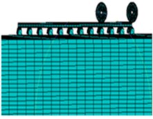
a)
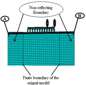
b)
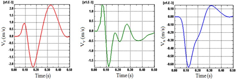
Considering the previously presented and verified computations in [26], the finite element package Abaqus/explicit analysis has been divided in to five stages, capable of predicating the dynamic response of the railway track under moving train loads. The illustration on each stage of wheel loading and moving is detailed in [26]. Note that to stabilize the vibrations in the railway tracks, the computation must end later; if not the steady state response can be claimed. Therefore, the analysis of this article completes when the velocity in the railway track is negligibly small (zero) (i.e. the steady state is essentially reached), as shown in Fig. 6.
Fig. 6Time histories of velocity on the track
4. Results and discussions
The 3D finite element models of train-induced ground vibration were simulated, by using Abaqus finite element package. All the FE model simulation results were reported in the time domains. A total period of 0.5 second for 120 km/h was considered and the vibration levels have been measured in two points at the right edge (Node B) and left edge (Node A) of the non-reflecting boundary, shown in Fig. 5(b).
Fig. 7Time histories of vertical velocity (Node B) for different length
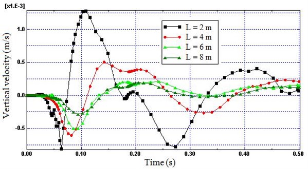
4.1. Length
The intensity of the wave propagated decreases as the distance from the wheel-rail interaction forces increases because the train induced vibration energy spread over increasing large area, consequently the reflection of the wave and superimpose with the progressing waves. Therefore, to evaluate the numerical value of the geometric dispersion and energy absorption of the non-reflecting region in respect to length, four different boundary lengths were considered in the model ( 2, 4, 6, 8 m). As shown in Figs. 7 and 8, the reflection is sharply decreased as length increases from 2 m to 4 m (57 %), while the effect of length on reflection is highly decreased as the length increase from 4 m to 8 m (27 %). Hence, Fig. 7 and Fig. 8 demonstrate that small length of the non-reflecting boundary far from the near-field would increase the boundary related waves reflection sharply.
Fig. 8Time histories of vertical velocity (Node A) for different length
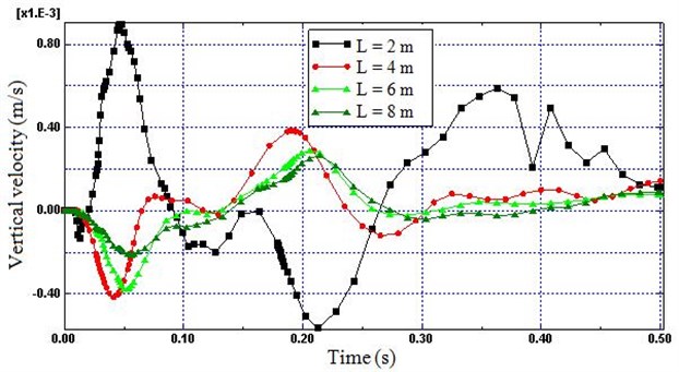
Fig. 9Time histories of vertical velocity (Node B) for different damping ratio
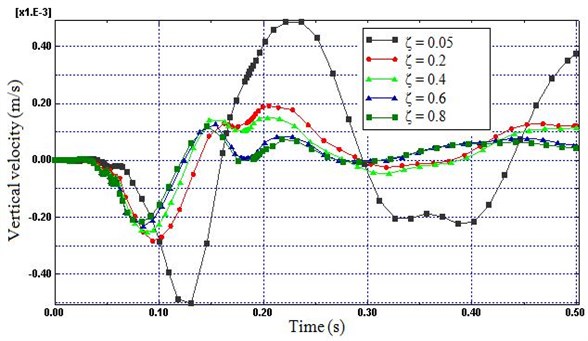
Fig. 10Time histories of vertical velocity (Node A) for different damping ratio
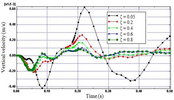
4.2. Damping ratio
The train induced vibration energy is expected to dissipate as a result of material damping of the soil model. Therefore, Fig. 9 and 10 is used to show the influence of damping ratio () to form a good non-reflecting boundary. Fig. 9 and 10 prove that small values of damping ratio do not generate enough dissipation force to avoid the distortion of the simulation results caused by the reflected wave. On the other hand, the variations in the nodal velocities of the boundary decreases highly as damping ratio of the soil raised from 0.05 to 0.6 (83 %). However, small change was observed as damping ratio was raised from 0.6 to 0.8 (13 %). Therefore, a damping ratio of 0.6 and above was deemed most efficient for minimizing the reflected wave.
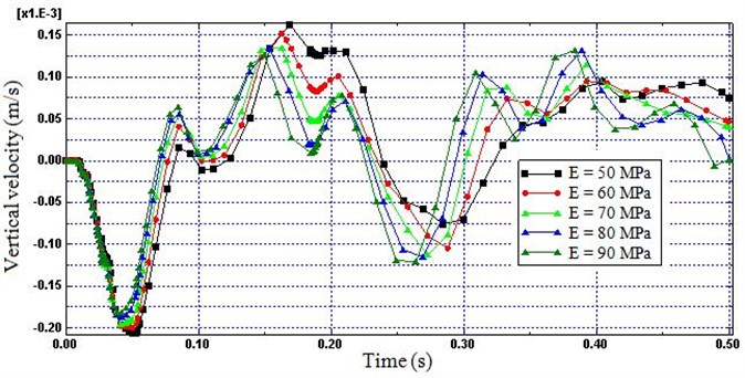
4.3. Young’s modulus
The graphs depicted in Fig. 11 and 12 illustrate the variations in the vertical velocity for five Young’s modulus (E) (i.e.; 50, 60, 70, 80 and 90 MPa). These graphs indicate that by increasing the Young’s modulus of the non-reflecting boundary, the reflection of the wave and superimpose with the progressing waves decreases. Again, as the Young’s modulus increases from 50 MPa to 90 MPa the percent decrease in the reflection was 22 %. Hence, higher reflection will be introduced by softer non-reflecting boundaries; however, as it is get closer to the hard rock the reflection may be increased due to contractile resistance of the layers.
Fig. 11Time histories of vertical velocity (Node B) for different modulus
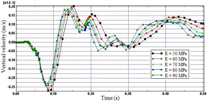
Fig. 12Time histories of vertical velocity (Node A) for different modulus
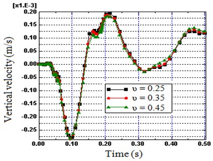
4.4. Poisson ratio
Since the stiffness of the soil somewhat depends on the Poisson’s ratio of the soil, hence its influence in minimizing the reflection is additionally computed. The vertical velocity computed at node B has been plotted with respect to the time domain for different Poisson’s ratio in Fig. 13. As can be seen in the peak response, a non-reflecting boundary with a Poisson’s ratio of 0.45 attenuates the reflection compared to 0.25 (5 %), but the direct effect of Poisson’s ratio in improving the efficiency of the proposed boundary is very small.
Fig. 13Influence of Poisson ratio on vertical velocity: on Node B
5. Conclusions
In this paper, the finite element method (FEM) is used to evaluate the non-reflecting boundary used for simulating ground borne vibrations and to investigate the effect of various parameters such as length, damping ratio, Young’s modulus and Poisson’s ratio of the boundary in screening the reflection caused by the moving train loads acting vertically on the ground. The study has been shown that defining of the non-reflecting boundary attached to the right and left end of the original model has a paramount important role; because it can be assigned a suitable material model differ from the field easily using the available finite element packages. Other observations are summarized in the following. The main emerging conclusion drawn below remains strictly valid for the conditions considered in the analysis, however the issue addressed is not specific to this package only.
1) The length of the non-reflecting boundary was seemed as the most important parameter on screening the boundary related wave reflection problems; especially a maximum increase in the reflection occurs when the crest of the boundary get closer to the original model. Hence, a sufficient length can be used to fully damp the spurious reflections from the sides of the model, but the computations are found to be considerably more costly.
2) The reflection decreases as damping ratio of the boundary increases. Additionally, the reflection decreases highly as damping ratio rises from 0.05 to 0.6, and it will be caused a decrease in length of the boundary consequently reduce the computational costs.
3) For a soil layer with defined non-reflecting boundary, the distortion of the simulation results caused by the reflection of wave decreases as the Young’s modulus increases; meanwhile a higher reflection will be introduced by softer non-reflecting boundary.
4) The influence of increasing the Poisson’s of the non-reflecting boundary is very small.
References
-
Kouroussis G., Connolly D. P., Verlinden O. Railway-induced ground vibrations - a review of vehicle effects. International Journal of Rail Transportation, Vol. 2, Issue 2, 2014, p. 69-110.
-
Leonardi G., Buonsanti M. Reduction of train-induced vibrations by using barriers. Research Journal of Applied Sciences, Engineering and Technology, Vol. 7, 2014, p. 3623-3632.
-
Yang Y. B., Hung H. H., Chang D. W. Train-induced wave propagation in layered soils using finite/infinite element simulation. Soil Dynamics and Earthquake Engineering, Vol. 23, Issue 4, 2003, p. 263-278.
-
Connolly D., Giannopoulos A., Forde M. C. Numerical modelling of ground borne vibrations from high speed rail lines on embankments. Soil Dynamics and Earthquake Engineering, Vol. 46, 2013, p. 13-19.
-
Yang Y. B., Hung H. H. A 2.5D finite/infinite element approach for modelling visco-elastic bodies subjected to moving loads. International Journal for Numerical Methods in Engineering, Vol. 51, Issue 11, 2001, p. 1317-1336.
-
Hall L. Simulations and analyses of train-induced ground vibrations in finite element models. Soil Dynamics and Earthquake Engineering, Vol. 23, Issue 5, 2003, p. 403-413.
-
Kouroussis G., Verlinden O., Conti C. Ground propagation of vibrations from railway vehicles using a finite/infinite element model of the soil. Journal of Rail and Rapid Transit, Vol. 223, Issue 4, 2009, p. 405-413.
-
Motamed R., Itoh Hirose K. S., Takahashi A., Osamu Kusakabe O. Evaluation of wave barriers on ground vibration reduction through numerical modeling in Abaqus. SIMULIA Customer Conference, 2009.
-
Thack P. N., Kongo G. Q. A prediction model for train-induced track vibrations. Electronic Journal of Geotechnical Engineering, Vol. 17, 2012, p. 3559-3569.
-
Elkacimi A., Woodward P. K., Laghrouche O., Medero G. Time domain 3D finite element modelling of train-induced vibration at high speed. Computers and Structures, Vol. 118, 2013, p. 66-73.
-
Thach P. N., Liu H. L., Kong G. Q. Vibration analysis of pile-supported embankments under high-speed train passage. Soil Dynamics and Earthquake Engineering, Vol. 55, 2013, p. 92-99.
-
Fu Q., Zheng C. Three dimensional dynamic analyses of track-embankment-ground systems subjected to high speed train loads. The Scientific World Journal, Vol. 2014, 2014, p. 924592.
-
Liu G. R., Quek Jerry S. S. A non-reflecting boundary for analyzing wave propagation using the finite element method. Finite Elements in Analysis and Design, Vol. 39, Issues 5-6, 2003, p. 403-417.
-
Drozdz M., Moreau L., Castaings M., Lowe M., Cawley P. Efficient numerical modelling of absorbing regions for boundaries of guided waves problems. AIP Conference Proceeding, Vol. 820, 2006, p. 126-133.
-
Serdaroglu M. S. Nonlinear Analysis of Pile Driving and Ground Vibrations in Saturated Cohesive Soils Using the Finite Element Method, Boundary Conditions for Time-Dependent Wave Propagation. Ph.D. Thesis, University of Iowa, 2010.
-
Mohammad S., Hossein H., Duczek S., Gabbert U. Non-reflecting boundary condition for Lamb wave propagation problems in honeycomb and CFRP plates using dashpot elements. Composites: Part B, Vol. 54, 2013, p. 1-10.
-
Galvın P., Romero A. A., Domınguez J. Fully three dimensional analysis of high-speed train track soil-structure dynamic interaction. Journal of Sound and Vibration, Vol. 329, Issue 24, 2010, p. 5147-5163.
-
Montalban L., Real J. I., Real T. Mechanical characterization of railway structures based on vertical stiffness analysis and railway substructure stress state. Proceedings of the Institution of Mechanical Engineers, Journal of Rail and Rapid Transit, Vol. 227, Issue 1, 2013, p. 74-85.
-
Antolin P., Zhang N., Goicolea J. M., Xia H., Astiz M. A., Oliva J. Consideration of nonlinear wheel-rail contact forces for dynamic vehicle-bridge interaction in high-speed railways. Journal of Sound and Vibration, Vol. 332, Issue 5, 2013, p. 1231-1251.
-
Sanudo R., Olio L. D., Casado J. A., Carrascal I. A., Diego S. Track transitions in railways. Construction and Building Materials, Vol. 112, 2016, p. 140-157.
-
Gallego I., Rivas A., Cambronero S. S., Ljara J. Dynamic modelling of high speed ballasted railway tracks: analysis of the behaviour. Transportation Research Procedia, Vol. 18, 2016, p. 357-365.
-
Llario F. R., Marzal S., Zamorano C., Real J. Numerical modelling of building vibrations due to railway traffic: analysis of the mitigation capacity of a wave barrier. Journal of Shock and Vibration, Vol. 2017, 2017, p. 4813274.
-
Beskou N. D., Theodorakopoulos D. D. Dynamic effects of moving loads on road pavements. Soil Dynamics and Earthquake Engineering, Vol. 31, Issue 4, 2011, p. 547-567.
-
Zhai W., He Z., Song X. Prediction of high-speed train induced ground vibration based on train-track-ground system model. Earthquake Engineering and Engineering Vibration, Vol. 9, Issue 4, 2010, p. 545-554.
-
Shan Y., Albers B., Savidis S. A. Influence of different transition zones on the dynamic response of track–subgrade systems. Computers and Geotechnics, Vol. 48, 2013, p. 21-28.
-
Aynalem M. Train induced pore water pressure generation model: numerical comparison. Journal of Vibroengineering, Vol. 21, Issue 4, 2019, p. 952-961.
Cited by
About this article

