Abstract
Theoretical modeling, parameters identification and vibration characteristic of heavy-loaded radial tire is investigated with rigid-elastic coupling model with normal damping. The normal damping, including structural damping of flexible carcass and proportion damping of distributed sidewall element is added to enrich the flexible beam on modified elastic foundation tire model. The rigid-elastic coupling tire model with normal damping is investigated and derived with finite difference method. The mass, stiffness and damping matrixes of the proposed tire model are analytically related with the structural and geometrical parameters of heavy-loaded radial tire. Taking the error between the analytical and experimental transfer function as the object value, Genetic Algorithm (GA) is utilized to identify the damping coefficients of flexible carcass and distributed sidewall element. The influence of modal order and tire damping parameters on the in-plane transfer function is discussed. The theoretical and experimental results show that the rigid-elastic coupling tire model with normal damping can achieve the sectional feature of in-plane transfer function resulting from the coupling characteristic between the flexible carcass and distributed sidewall element within the frequency band of 300 Hz.
1. Introduction
In recent years, the maneuver stability [1], smoothness [2] and braking safety [3] of the heavy-loaded vehicles have become being of vital importance in the automotive community, especially the speed is exceeding towards higher. As only link between the road and vehicle, the heavy-loaded radial tire is required to perform multiple functions, not only supporting the weight and cushioning the irregularities of road, but also providing the desired braking/traction and lateral force for vehicle control system. So, dynamics of the heavy-loaded radial tire influences largely the main performance indexes of heavy vehicle, including ride comfort [2], power [4], economy [4] and maneuver stability [1].
Despite the simple appearance, tire is a complex composite structure consisting of carcass, tread and sidewall, meanwhile carcass and sidewall are the most essential ones affecting the tire behavior. As the base of the tire, the carcass is needed to support the load, hold the internal air pressure and filter the road irregularities; meantime the sidewall transmits the forces acted from the tire-road contact zone to the rim. The carcass and sidewall both consist with steel and bonded layers of cords and rubber to provide the strength against the inflation pressure. With the development of the computational numerical method, non-linear Finite Element [5], ANCF Finite Element [6] and Spectral Element Formulation [7] are utilized to describe the geometrical and material feature of tire in detail for the application of tire design and tire wear analysis. However, the comprehensive numerical computation of the detailed tire model increases the difficulty of real-time simulation and hinders effective vehicles system application. In order to avoid the comprehensive computation of the detailed tire model, structural tire model is investigated with the combined advantage of high the simulation precision and efficient computation. Analytical modal frequency and vibration feature can be obtained and the structural tire model can be easily extended to the vehicle systems dynamics.
As the tropical respective of the structural tire model, significant research effort is dedicated to the flexible continuous carcass tire models [8] over the past decade. Flexible continuous carcass tire model simplifies the tire as the flexible continuous carcass (string, beam, ring, plate and shell) acting on elastic foundation, in which continuous carcass refers to flexible carcass, meantime sidewall and inflation pressure refer to elastic foundation. Flexible continuous carcass tire model is investigated with the continuum mechanics theory and the nonlinear characteristic resulting from the geometrical and structural feature of tires can be added into the flexible continuous carcass tire model. Deformation of carcass and in-plane vibration can be analytical derived and extended to the vehicle system dynamics.
With the larger flat ratio (the ratio of sidewall radii to carcass width) (0.98 for heavy loaded radial tire, nearly closed to 1) of the heavy-loaded radial tire, the in-plane coupling characteristic of flexible carcass and circumferential distributed sidewall is highlighted and the coupling vibration modal of flexible carcass and circumferential distributed sidewall was investigated in the prior research [9] utilizing the flexible continuous beam on modified elastic foundation tire model. The influence of structural parameters on in-plane coupling modal frequency was analyzed. However, the coupling partial differential equation of the flexible carcass kinematics between the space and time domain deformations should be decoupled during the rolling and contact analysis, so the coupling characteristic between space-domain deformation and time-domain deformation the flexible carcass increases the difficulty of the rolling characteristic analysis utilizing the flexible continuous carcass tire model.
Flexible distributed carcass tire model [10-12] is proposed by the distributed carcass segment and decouples the space deformation and time domain deformation of flexible carcass. The finite carcass segment tire model is presented and modeled by Umstrithong [10]; FTire tire model [11] is developed with the distributed carcass and the distributed carcass segment is connected with bending and stretching spring, while the stiffness of the spring connecting the carcass element has no physical meaning; constraint mode tire model [12] is proposed by dividing the tire carcass into element and each segment is modeled as an Euler elastic beam, while the inflation pressure is ignored. The most important challenge is that the existing research mainly focuses on the interaction movement between the flexible carcass and rim and the sidewall acts as the elastic foundation which is suitable for the passenger and car tires with a little flat ratio (respectively 0.5 and 0.3). For the heavy-loaded radial tire with a large flat ratio, the coupling characteristic between the flexible carcass and circumferential distributed sidewall segment is highlighted and the modified elastic foundation is considered for the sidewall foundation.
The rigid-elastic coupling tire model with the modified elastic foundation is proposed and derived based on the flexible beam on modified elastic foundation tire model [9] and the in-plane normal damping of the heavy-loaded radial tire, including structural damping of flexible carcass and proportion damping of distributed sidewall element is modeled. The modal parameters of the heavy-loaded radial tire, including modal resonant frequency and transfer function are discussed.
The rest of the paper is organized as follows: The rigid-elastic coupling tire model with normal damping of heavy-loaded radial tire is derived and the in-plane analytical modal resonant frequency of the proposed tire model is investigated and compared with the experimental results in Section 2. The in-plane experimental transfer function is presented and the damping coefficients are identified utilizing Genetic Algorithm in Section 3. The influence of modal truncation order and tire damping coefficients on in-plane transfer function is investigated in Section 4.
2. Rigid-elastic coupling tire model with normal damping
2.1. Flexible beam on modified elastic foundation with normal damping
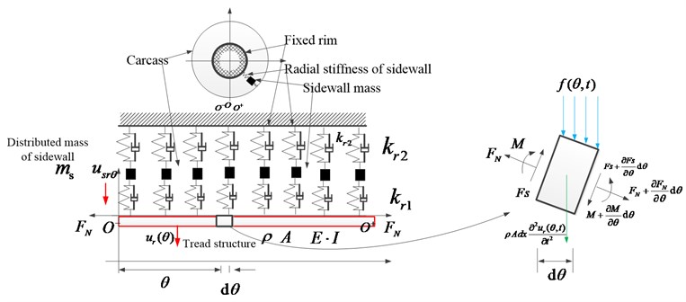
In-plane tire model is based on the flexible beam on modified elastic foundation tire model and consists with three critical sections (Fig. 1):
(1) Flexible carcass is simulated with Euler beam and the axis force of the Euler beam [13] is considered resulting from the inflation pressure;
(2) Circumferential distributed sidewall segment refers as the radial spring with two-sectional spring force and the inertia force;
(3) Normal damping, including the structural damping of flexible carcass and the proportion damping of sidewall radial spring, is added to enrich the rigid-elastic coupling tire model.
Fig. 1Flexible beam on modified elastic foundation with structural damping
Resulting from the inner material friction, the structural damping of flexible carcass is considered and the dynamic stress of flexible carcass is dependent on the strain and strain velocity shown as:
where, is the horizontal displacement of the carcass micro-segment at the time and for short, is utilized for substitute ; is the strain of the carcass micro-segment; is the stress of the carcass micro-segment; is elasticity modulus; is the structural damping coefficient and dependent on the material property.
Bending moment refers as Eq. (2):
where, is the bending moment of flexible carcass; is the bending stiffness of flexible carcass; is inertia moment of cross section and , is carcass width and is carcass thickness; is carcass radius.
Equations of force and moment balance of the flexible carcass micro-segment are respectively shown in Eq. (3):
where, is the shear moments of the carcass cross-section; is the inertial forces of the carcass micro-segment and is the density per line of carcass; is the interaction force between the carcass micro-section and the distributed sidewall segment, ; is the horizontal displacement of the sidewall segment at the time ; is the radial stiffness connecting the carcass micro-section and the distributed sidewall segment and is the radial proportion damping connecting the carcass micro-section and the distributed sidewall segment; is the external moment of the microsegment and ; is the axil pre-tension force of flexible carcass resulting from the inflating pressure and , is inflation pressure.
Substituting Eq. (3b) and Eq. (2) in Eq. (3a), In-plane bending dynamics of flexible carcass is derived as:
Dynamics of in-plane coupling vibration equation of flexible carcass and distributed sidewall element with normal damping is derived as:
where, Eq. (5a) is the bending vibration equation of flexible carcass, and are respectively the damping characteristic of flexible carcass and sidewall element (connecting flexible carcass and distributed sidewall element); Eq. (5b) is the radial vibration equation of distributed sidewall segment, and are respective the damping feature of distributed sidewall element; is the rad density of sidewall; is the radial stiffness connecting the distributed sidewall segment and tire rim; is the radial proportation damping connecting the distributed sidewall segment and tire rim.
Taking the error between the analytical modal resonant frequency and the experimental modal resonant frequency as the object value, Genetic Algorithm [9] was utilized to identify the structural and geometrical parameters. The identified results are listed in Table 1.
Table 1Parameters of heavy-loaded radial tire
Parameters | Symbol | Unit | Identified value |
Carcass width | M | 0.35 | |
Inflation pressure | N/m2 | 8×10⁵ | |
Carcass radius | M | 0.65 | |
Density per rad of sidewall | kg/rad | 10 | |
Density per line of carcass | kg/m | 19.64 | |
Radial stiffness connecting the sidewall and carcass | N/m | 6.686×10⁶ | |
Radial proportation damping connecting the sidewall and carcass | N/(m/s) | Un-known | |
Radial stiffness connecting the sidewall and rim | N/m | 4.431×10⁶ | |
Radial proportation damping connecting the sidewall and rim | N/(m/s) | Un-known | |
Bending stiffness of carcass | N/m | 25.697 |
2.2. Rigid-elastic-coupling tire model
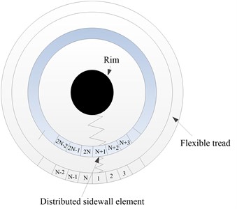
The in-plane rigid-elastic coupling tire model is derived with flexible beam on modified elastic foundation tire model and the flexible carcass is discreted into segments with finite difference method shown in Fig. 2. The difference forms of the one-order, second-order and fourth-order utilized in Eq. (5) refer as:
Fig. 2Scheme of rigid-elastic coupling tire model
The in-plane flexible beam on modified elastic foundation model is transformed:
Namely, the rigid-elastic coupling tire model with normal damping is derived as:
By simultaneously analyzing the elements of flexible carcass, the two order differential equation of in-plane rigid-elastic coupling tire model with freedom of can be referred as below:
where:
The in-plane rigid-elastic coupling tire model shows that:
(1) The equivalent mass parameters and of rigid-elastic coupled tire model are related with the density of carcass and sidewall;
(2) Three equivalent parameters: , and of stiffness matrix are related with the geometrical and structural parameters which enable the analytical vibration analysis of heavy loaded radial tire;
(3) Three equivalent parameters: , and of damping matrix are related with the damping characteristic of carcass and sidewall.
2.3. Modal resonant frequency analysis
In order to validate the modal analysis ability of rigid-elastic coupling tire model, the experimental modal test with coupling feature of flexible carcass and distributed sidewall element is proposed and presented.
2.3.1. Analytical modal resonant frequency
The analytical coupled vibration modal of heavy-loaded radial tire is derived utilizing modal expansion method and the free vibration mode of the flexible carcass and the distributed sidewall is assumed in the sinusoidal series as:
Substituting Eq. (10) into Eq. (5), the coupled dynamics of heavy-loaded radial tire refer as:
Simplification:
Result is obtained as:
where:
Analytical modal resonant frequency of the flexible tread and the circumferential distributed sidewall is derived as:
The two roots of Eq. (14) is discussed as:
The Eq. (17) is the identical equation:
(1) , substituting Eq. (17) into Eq. (15), , implying the same vibration direction of flexible tread and continuous sidewall;
(2) substituting Eq. (17) into Eq. (16), implying the opposite vibrationdirection of flexible tread and continuous sidewall.
2.3.2. Experimental modal resonant frequency
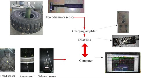
Fig. 3 shows the hardware implementation of experimental modal test with coupling feature of flexible carcass and distributed sidewall element.
The step to implement the experimental modal analysis is list below:
(1) The tire carcass is dived into 34 sections in the circumference direction and moving hammer method is utilized (Fig. 3(b));
(2) Vibration acceleration sensor of PCB is pasted respectively in the tire carcass and sidewall (Fig. 3(c));
(3) With the measurement means of the B&K force hammer transducer and PCB acceleration sensor, the exciting force and the responding acceleration are acquired by DE-43 data collector;
(4) The in-plane transfer function is computed with the spectrum method;
(5) The transfer functions of carcass radial response-carcass radial excitation, sidewall radial response-carcass radial excitation, and rim radial response-carcass radial excitation are summed up as the object transfer function;
(6) The modal parameters, including resonant frequency, modal damping, participation factor and modal shape are calculated with least squares complex exponential method (LSCE) by fitting the object transfer function.
Fig. 3Implement of experimental modal test
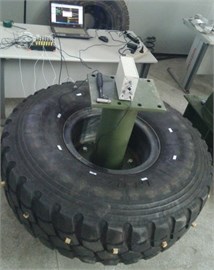
a) Experiment implementation of modal test
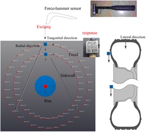
b) Scheme of experimental modal test
c) Hardware implementation of modal test
Eq. (14) presents the analytical modal frequency of heavy-loaded radial tire solved with the modal expansion method. The analytical modal resonant frequency of rigid-elastic coupling tire model with 200 are compared with the experimental modal frequency and modal frequency calculated by Eq. (14) in Fig. 4.
Fig. 4Compared figure between the analytical and experimental modal resonant frequency
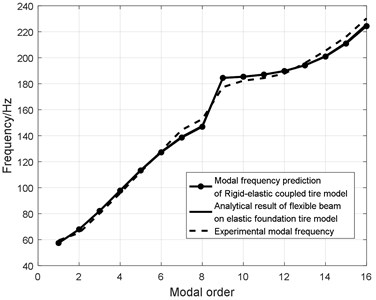
The compared result (Fig. 4) shows that:
(1) The error between the analytical modal frequency of flexible beam on modified elastic model and the experimental modal frequency is within 4 %, while the analytical modal resonant frequency of rigid-elastic coupling tire model fits well with the analytical modal frequency calculated by Eq. (14);
(2) The modal resonant frequency is divided into two parts: the first is the modal of the first to eighth order (0-160 Hz) with the modal shape of same direction of flexible carcass (Fig. 5(a)) and distributed sidewall element; the second is the modal of the ninth to sixteenth order (160-300 Hz) with the modal shape of opposite direction of flexible carcass (Fig. 5(b)) and distributed sidewall element;
(3) The modal shapes of heavy-loaded radial tire within 300 Hz are featured as harmonic characteristic and the harmonic characteristic of tires is influenced by the in-plane bending vibration of the flexible carcass and circumferential sidewall, which agrees with the flexible Euler beam theory;
(4) The modal shape of the first to eighth modal order is the same-direction coupled vibration of flexible carcass and circumferential sidewall and the bending direction of the flexible carcass and circumferential sidewall is same (Fig. 5(a));
(5) The modal shape of ninth to sixteenth modal order is the opposite-direction coupled vibration of flexible carcass and circumferential sidewall and the bending direction of the flexible carcass and circumferential sidewall is opposite (Fig. 5(b));
(6) The analytical vibration direction of flexible carcass and circumferential sidewall (Eq. (15)) of first to eighth modal order agree with the experimental result with same-direction coupled vibration of flexible carcass and circumferential sidewall;
(7) The analytical vibration direction of flexible carcass and circumferential sidewall (Eq. (16)) of ninth to sixteenth modal order agree with the experimental result with opposite-direction coupled vibration of flexible carcass and circumferential sidewall;
(8) Rigid-elastic coupling tire model is qualified to predict the in-plane modal feature of heavy-loaded radial tire, which validates the modal analysis effectiveness of the rigid-elastic coupling tire model.
Fig. 5Experimental modal shape [9]
![Experimental modal shape [9]](https://static-01.extrica.com/articles/19191/19191-img7.jpg)
a) Fifth modal order with five-sectional shape
![Experimental modal shape [9]](https://static-01.extrica.com/articles/19191/19191-img8.jpg)
b) Thirteenth modal order with five-sectional shape
3. In-plane transfer function analysis of heavy-loaded radial tire
In-plane transfer function is the basic of the deformation and rolling analysis of tire decided not only by the structural and geometrical parameters (Table 1), but also by the damping coefficients. Better knowledge of damping feature lays the precision basic of the in-plane transfer function, so the damping coefficient is identified.
3.1. Analytical transfer function of rigid-elastic coupling tire model
Equation of frequency domain is transformed from that of time domain (Eq. (9) for rigid-elastic coupling tire model with normal damping):
The displacement transfer matrix refers as :
Damping matrix is consisted with two parts: structural damping matrix of flexible carcass and proportional damping matrix of sidewall radial spring and both two matrixes are symmetric. As proportional feature of damping matrix , the matrixes , and can be orthogonal with the modal shape matrix:
where, is the modal shape matrix, , is the vector of th modal shape; - is the modal shape with the same direction of flexible carcass and circumferential sidewall element (Fig. 5(a)); - is the modal shape with the same direction of flexible carcass and circumferential sidewall element (Fig. 5(b)).
Displacement transfer matrix is calculated as:
where, the frequency and damping respectively refer as: , .
Acceleration transfer function is calculated as:
By considering the sectional modal feature of heavy-loaded radial tire, the piecewise modal truncation method is utilized and presented below:
where, is the calculated modal order.
3.2. Implement of hammer test
Experimental transfer function with the rim fixed condition is obtained by hammer test shown in Fig. 6. Exciting force is measured by the hammer sensor of B&K and the vibration response is measured by the acceleration sensor of PCB. The exciting force and acceleration response are gathered by the high-speed data acquiring equipment of DEWE-43.
The carcass is excited at the carcass point: A by hammer sensor and vibration response of point A are gathered (Fig. 6).
Fig. 7 shows that:
(1) Transfer function of in-plane vibration for heavy-loaded radial tire within 300 Hz can be divided into two parts: vibration feature between 0 to 160 Hz and vibration feature between 160 to 300 Hz;
(2) The sectional transfer function agrees with the sectional feature of modal frequency (Fig. 5).
The sectional transfer function can be explained as the different vibration feature between the flexible carcass and distributed sidewall element result from the larger flat ration of heavy-loaded radial tire.
Fig. 6Hammer test
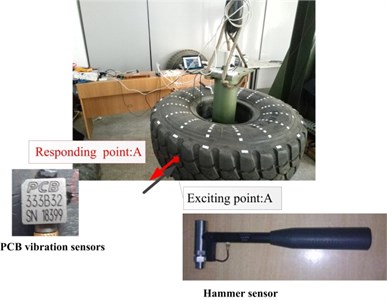
Fig. 7In-plane experimental transfer function
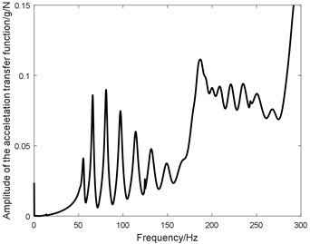
a) Amplitude of transfer function
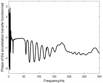
b) Phase of transfer function
3.3. Damping coefficient identification
Taking the error between the analytical transfer function (Eq. (22)) and experimental transfer function (Fig. 7), Genetic Algorithm (GA) [14] is utilized to identify the normal damping coefficient, including the structural damping of flexible carcass and proportion damping of radial sidewall spring. Based on natural selection and genetic theory, GA combining the survival of fittest rules and the exchange mechanism of random chromosomes information forms the efficient global optimization search algorithm and the whole scheme of damping coefficient identification is shown in Fig. 8.
Genetic Algorithm is initialized as population size: 50; generations: 300; generation gap: 0.9; crossover rate: 0.7 and mutation rate: 0.1. Object value and damping coefficients of the optimization procedure are respectively shown in Figs. 9, 10.
The optimization results (Figs. 9, 10) imply that:
(1) The object value (Fig. 9) is convergent to the steady point when the optimization procedure proceeds to 15 generations and the minimum value of object value is 0.01;
(2) The damping coefficient of flexible carcass converges to the steady value (9×10⁻⁴) as the optimization procedure proceeding 150 generations (Fig. 10(a));
(3) The damping coefficient of sidewall radial converges to the steady point (1.25×10⁻⁴) when the optimization procedure proceeds to 150 generations (Fig. 10(b));
(4) The damping coefficient of sidewall radial converges to the steady point (1.81×10⁻⁴) when the optimization procedure proceeds to 150 generations (Fig. 10(c)).
Fig. 8Scheme of damping coefficient identification

Fig. 9Object value of optimization procedure
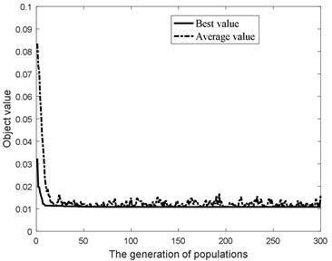
Fig. 11 show the compared results between the experimental transfer function and analytical transfer function of rigid-elastic coupling tire model with the identified damping coefficient.
The compared results (Fig. 11) imply that:
(1) The resonant frequencies of the analytical transfer function fit well with that of the experimental transfer function;
(2) The amplitude of the analytical transfer function at 55.576 Hz is larger than that of the experimental transfer function, while the amplitude of the analytical transfer function at 179.076 Hz is lower than that of the experimental transfer function;
(3) The deviation presents in the amplitude of analytical transfer function, especially at the shift modal frequency (55.576 Hz and 179.076 Hz) can be explained that the lumped mass modeled in the rigid-elastic coupling tire model is different from the circumferential distributed mass of sidewall along the tire radial direction. The in-plane rigid-elastic coupling tire model presented in the paper overestimates the inertial force of circumferential distributed sidewall segment, meantime the vibration characteristic of the shift modal shape is dependent on the stiffness and mass;
(4) The coupling vibration feature of the carcass and sidewall divides the transfer function within 300 Hz into two sections, in which the transfer function within the frequency band 0-180 Hz refers as the same-direction coupling vibration between the flexible carcass and the circumferential sidewall segments, meantime the transfer function within the frequency band 180-300 Hz refers as the opposite-direction shape coupling vibration between the flexible carcass and the circumferential sidewall segments;
Fig. 10Damping coefficients of optimization procedure
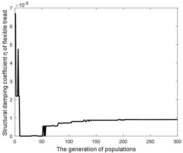
a) Damping coefficient of flexible carcass
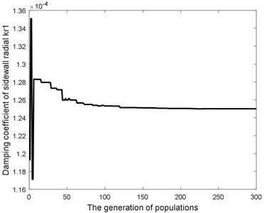
b) Damping coefficient of sidewall radial
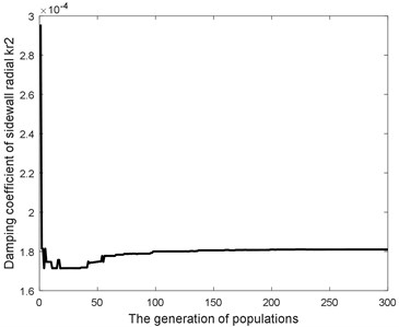
c) Damping coefficient of sidewall radial
Fig. 11Compared figure between the experimental transfer function and analytical transfer function with identified damping coefficients
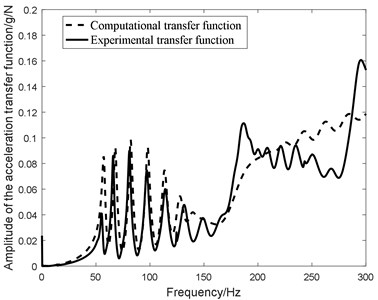
a) Amplitude of transfer function
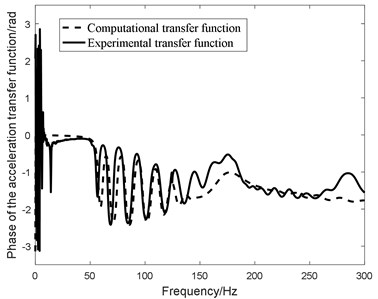
b) Phase of transfer function
(5) The transfer function within the frequency band 0-180 Hz is consistent with the same-direction coupling vibration between the flexible carcass and the circumferential sidewall segments;
(6) The transfer function within the frequency band 180-300 Hz is coincident with the opposite-direction coupling vibration between the flexible carcass and the circumferential sidewall segments.
4. Discuss
The in-plane transfer function calculated with piecewise modal truncate method is compared with different truncate modal order and the influence of the damping coefficients on in-plane transfer function is discussed.
4.1. Influence of modal order on transfer function
Fig. 12 shows that the analytical transfer function of rigid-elastic coupling tire model with different truncate modal orders.
The compared result illustrates that:
(1) The analytical transfer function with the truncate modal order being 20 underestimates the high frequency response above 260 Hz;
(2) With the truncate modal order larger than 40, the deviation between the analytical transfer function and experimental transfer function is not obvious within 300 Hz;
(3) The analytical transfer function with modal order 100 is adequate to character the in-plane sectional transfer function of heavy-loaded radial tire.
Fig. 12In-plane analytical transfer function with different truncate modal order
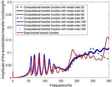
a) Amplitude of transfer function
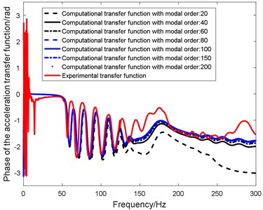
b) Phase of transfer function
4.2. Influence of tire damping on in-plane transfer function
Consisting with the structural damping of flexible carcass and proportion damping , of sidewall springs, the normal damping of rigid-elastic coupling tire model influences largely the attenuation of vibrations with increasing frequency.
The influence of different damping parameters on the in-plane transfer function is researched and investigated utilizing the single variable method.
Initial damping coefficients of heavy-loaded radial tire identified by GA are list as , and .
Fig. 13 presents the compared transfer function with proportion damping coefficients of 80 percent, 100 percent and 120 percent of damping parameters.
Fig. 14 illustrates the compared transfer function with proportion damping coefficients of 80 percent, 100 percent and 120 percent of damping parameters.
Fig. 15 presents the compared transfer function with structural damping coefficients of 80 percent, 100 percent and 120 percent of damping parameters.
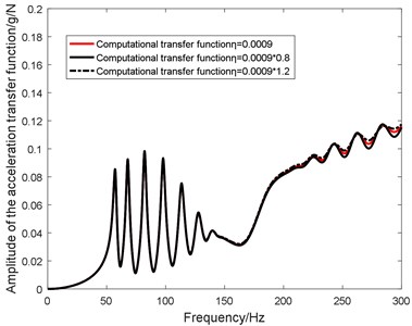
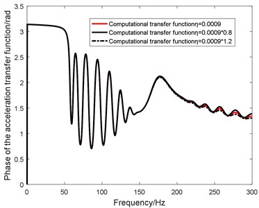
Fig. 13Influence of cr1 on in-plane transfer function
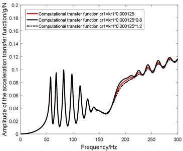
a) Amplitude of transfer function
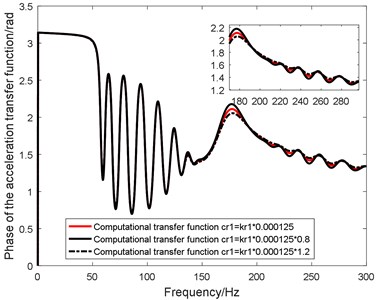
b) Phase of transfer function
Fig. 14Influence of cr2 on in-plane transfer function
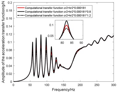
a) Amplitude of transfer function
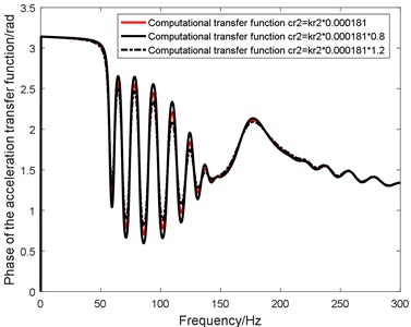
b) Phase of transfer function
Fig. 15Influence of η on in-plane transfer function
a) Amplitude of transfer function
b) Phase of transfer function
The influence of different damping coefficients on in-plane transfer function is investigated in Figs. 13, 14 and 15 and the compared results imply that:
(1) Sidewall proportion damping mainly influences the transfer function within 160-300 Hz and affects largely the opposite vibration feature of flexible carcass and distributed sidewall element;
(2) Sidewall proportion damping mainly influences the transfer function within 0-160 Hz and influence largely the same vibration feature of flexible carcass and distributed sidewall element;
(3) Structural damping of flexible carcass mainly influences the amplitude of high-order transfer function, while the influence on the transfer function within 230 Hz is not apparent.
5. Conclusions
Taking the coupling feature of flexible carcass and circumferential distributed sidewall segment into consideration, rigid-elastic coupling model with normal damping is investigated theoretically and validated by experiment results.
The main works can be concluded as:
1) With the means of finite difference method, the rigid-elastic coupling tire model is developed from the flexible beam on modified elastic foundation tire model;
2) The normal damping, including structural damping of flexible carcass and proportion damping of distributed sidewall element is investigated and added to enrich the proposed tire model;
3) Taking the error between the analytical and experimental transfer function as the object value, Genetic Algorithm (GA) is utilized to identify the damping coefficients of rigid-elastic coupling tire model and the influence of tire damping parameters on the in-plane transfer function is discussed.
The main results are concluded:
1) The vibration characteristic of heavy-loaded radial tire is investigated with rigid-elastic coupling tire model, including analytical modal frequency and transfer function; the compared results of the modal resonant frequency and transfer function validates the effectiveness of vibration analysis utilizing rigid-elastic coupling tire model with normal damping;
2) The proportion damping coefficients of distributed sidewall element and influence respectively the opposite and same vibration feature between flexible carcass and distributed sidewall element, while the structural damping of flexible carcass influences the vibration attenuation of transfer function within the high order modal.
References
-
Chen Long, Luo Yugong, Bian Mingyuan, Qin Zhaobo, Luo Jian, Li Keqiang Estimation of tire-road friction coefficient based on frequency domain data fusion. Mechanical Systems and Signal Processing, Vol. 85, 2017, p. 177-192.
-
Pazooki Alireza, Rakheja Subhash, Cao Dongpu Modeling and validation of off-road vehicle ride dynamics. Mechanical Systems and Signal Processing, Vol. 28, 2012, p. 679-695.
-
Li Jingliang, Zhang Yizhai, Yi Jingang A hybrid physical-dynamic tire/road friction model. Journal of Dynamic Systems, Measurement, and Control, Vol. 135, 2013, p. 011007.
-
Soltani Amir, Goodarzi Avesta, Shojaeefard Mohamad Hasan Optimizing tire vertical stiffness based on ride, handling, performance, and fuel consumption criteria. Journal of Dynamic Systems, Measurement, and Control, Vol. 137, Issue 12, 2015, p. 121004.
-
Li Hao, Schindler Christian Transient dynamics of an excavator tyre rolling over speed bump. Proceedings of the Institution of Mechanical Engineers, Part K: Journal of Multi-body Dynamics, Vol. 228, Issue 3, 2014, p. 229-240.
-
Patel Mohil, Orzechowski Grzegorz, Tian Qiang, Shabana Ahmed A. A new multibody system approach for tire modeling using ANCF finite elements. Proceedings of the Institution of Mechanical Engineers, Part K: Journal of Multi-body Dynamics, Vol. 230, Issue 1, 2016, p. 69-84.
-
Huang Dishan, Tang Liang, Cao Rui Free vibration analysis of planar rotating rings by wave propagation. Journal of Sound and Vibration, Vol. 332, 2013, p. 4979-4997.
-
Masami Matsubara, Daiki Tajiri, Tomohiko Ise Vibrational response analysis of tires using a three-dimensional flexible ring-based model. Journal of Sound and Vibration, Vol. 408, 2017, p. 368-382.
-
Liu Zhihao, Gao Qinhe In-plane vibration modal analysis of heavy-loaded radial tire with a larger flat ratio. Journal of Vibroengineering, Vol. 19, Issue 7, 2017, p. 5327-5345.
-
Corina Sandu, Anake Umsrithong Discrete mass tyre model for ride investigation over uneven rigid terrain. International Journal of Vehicle Design, Vol. 66, Issue 1, 2014, p. 87-106.
-
Gipser Michael FTire and puzzling tyre physics: teacher, not student. Vehicle System Dynamics, Vol. 54, Issue 4, 2016, p. 448-462.
-
Ma Rui, Ferris John B., Reid Alexander A., Gorsich David J. A planar quasi-static constraint mode tyre model. Vehicle System Dynamics, Vol. 53, Issue 12, 2015, p. 1759-1771.
-
Lee Jongsuh, Wang Semyung, Pluymers Bert, et al. A modified complex modal testing technique for a rotating tire with a flexible ring model. Mechanical Systems and Signal Processing, Vols. 60-61, 2015, p. 604-618.
-
Bagheri M., Jafari A. A., Sadeghifar M. Multi-objective optimization of ring stiffened cylindrical shells using a genetic algorithm. Journal of Sound and Vibration, Vol. 330, 2011, p. 374-384.
About this article

