Abstract
The structural system with better seismic performance is one of the key to the seismic design of cable-stayed bridges. The research shows that the internal force response of floating system is small and the displacement response is large, and the seismic response of the hinged system is the opposite. However, the tower bottom moment of the fix hinged cable-bridge could be less than it of the floating system actually, because the inertia force of the girder in the hinge system would be transmitted to the tower through the connection of tower and girder. In the light of these characteristics, a new low-gravity cable-stayed bridge seismic structure system, the safe-belt constraint system, is proposed in this paper, and the seismic response characteristics are studied by ANSYS. In addition, the effect of safe-belt parameters on the vibration reduction effect of the belt system cable-stayed bridge is analyzed.
1. Introduction
The seismic conceptual design for bridges is divided into the seismic isolation design and ductility design. The seismic isolation design is a method of seismic design, which aims at rigid bridge with short cycle. The ductile design theory proposes the plastic hinge of the capability protection member to resist seismic action [1, 2]. However, the structural cycle of the cable-stayed bridge is generally long, so the effect of the seismic isolation design and ductility design to reduce the longitudinal seismic response of the cable-stayed bridge is not obvious. There’s a great deal research shows that the connection mode among cable-stayed bridge tower, beam and pier has a great impact on static and dynamic performance. According to the structural characteristics of cable-stayed bridge, it is critical to choose the structural system with better seismic performance in the seismic design of cable-stayed bridge [3]. The seismic behavior, the advantages and disadvantages and the application range of the cable-stayed bridge with different structural systems were deeply studied by Fan. The structural system of the cable-stayed bridge is divided into floating system, the hinged system and asymmetric restraint according to the connection mode of cable-stayed bridge tower, beam and pier, beam and pier. It is generally believed that the force response of the control section of the floating system is small under the action of earthquake, but the longitudinal displacement of the key point is relatively large. The hinged system can effectively control the longitudinal displacement of the key point under the seismic load, but the shearing force of the structural control section is large. The recent studies have shown that the internal force response usually decrease at the cost of increasing displacement, and vice versa [4]. Researchers have systematically studied the seismic performance of elastic restraint system cable-stayed bridge, viscous damper restraint system cable-stayed bridge and both damper and elastic connection structural system cable-stayed bridge [5-7].
For the double tower low center of gravity cable-stayed bridge [8-10], its main beam span is large, there is plenty of demand for the main girder deformation of fixed hinge system in temperature, shrinkage and creep, and the internal force of the structure. For the low center of gravity cable-stayed bridge under temperature load, it is difficult to meet the design requirements because the pillar lateral stiffness is large. If the floating system should be adopted, the secondary internal force caused by the deformation of the main girder can be controlled, but the seismic response of the floating system with low center of gravity is relatively large. The asymmetric restraining system can not only avoid the larger secondary internal force caused by the deformation of the main girder, but reduce the seismic displacement response of the cable-stayed bridge. However, under the earthquake load, the double tower internal forces are very different and not conducive to the synergistic seismic capacity of the double tower. In order to compensate the shortcomings of the conventional structural system of the cable-stayed bridge, a new seismic structure system, safe-belt constraint system, is proposed. Under the normal working condition, for the asymmetric restraint system, the deformation of the main girder can be satisfied. When the earthquakes occur, it is activated by seismic acceleration, so that the cable-stayed bridge structure system immediately converts into a good earthquake-resistant hinged system, which provides a new choice for the selection and design of cable-stayed bridge, and it is of great significance to the seismic study of cable-stayed bridge.
2. Safe-belt constraint system of low gravity center cable-stayed bridge
At present, it is concluded that the internal force response and displacement response of the hinged system of the low center of gravity cable-stayed bridge are smaller than that of the floating system, and the hinged system is the preferred seismic structure system of the low center of gravity cable-stayed bridge. But under the normal working condition, due to the deformation of temperature, shrinkage and creep, the internal forces of the hinged system will cause great secondary internal force between the tower and the girder, so it is difficult to meet the design requirements. So, the application of the hinged system in the project has been limited. Although the asymmetric restraint system has a small displacement response, the seismic response of the two towers is very different due to the inhomogeneous force transmission, which is not conducive to the seismic capacity of the two towers. Therefore, a new type of the low center of gravity cable-stayed bridge seismic structure system, the safety-belt structure system, has been put forward, in which the hinged connection is used between a tower and the girder and a safe-belt constraint connection is used between the other tower and the girder. In that case, the secondary internal force caused by the deformation of the main girder under the normal working condition could be controlled, and it make good use of the advantages of the hinged system under the action of the earthquake.
2.1. Safe-belt constraint device structure
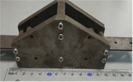
The main components of a safe-belt constraint device are a safety belt, an upper seal plate, a locking roller, a partition board, a stationary roller cap, a lower floor plate, and an adjustable yield control unit of the tonnage. As shown in Fig. 1 and Fig. 2, the safety belt through the bottom plate is fixed to the transverse beam of bridge tower, the upper sealing plate and the lower bottom plate are fixed according to the designed angle, and the stationary roller cap is fixed in the closing device formed by the lower bottom plate and the upper sealing plate. The safe-belt and the beam are connected by a bracket. Based on friction locking principle, the longitudinal connection of the tower and the girder can be changed for the different position of the locking shaft. Safe-belt constraint device has many advantages, such as its low cost, good durability, convenient inspection, and so on. Under normal service condition, the safe-belt constraint device is not activated, longitudinal free sliding can occur between the tower and the beam. When the earthquake bursts, the safety t belt connecting device will be activated by acceleration of ground motion, the safety belt is locked that caused the longitudinal sliding between the tower and the beam cannot occur, and the inertial force transmission force is uniform, thus reducing the seismic response of the cable-stayed bridge and improve the seismic performance of cable-stayed bridge.
Fig. 1The normal working state of the safe-belt
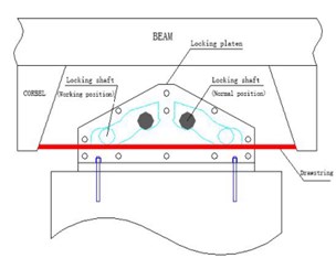
Fig. 2The view of safe-belt connection system
2.2. Unit constitutive model of safe-belt constraint device
According to the structure and working principle of the safety belt, the unit constitutive model of the seismic acceleration safe-belt constraint device is shown in Fig. 3, in which is the acceleration activation threshold; is the initial gap; is the locking gap; is the locking stiffness; is the unit damping coefficient; is the pull-slip force; and is the tensile stiffness.
Fig. 3Mechanical model of safe-belt constraint system
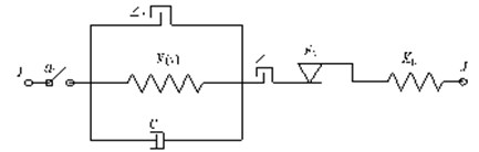
Before the acceleration of the pier top reaches the acceleration activation threshold for the first time, the safety belt is not activated, and the bridge tower and the beam can slide freely. When the acceleration of the pier top reaches the acceleration activation threshold for the first time, the locking shaft rolls out of the stationary roller cap and into the roller channel, with locking shaft position changes, the friction between the locking shaft and the pull bar is increasing, caused the safety belt device was been locked, finally tower and beam are fixed and hinged. For the convenience of expression:
where, is time pier top acceleration; for the pier top acceleration value for the first time to reach the acceleration activation threshold time. According to the working principle of the safety belt, the constitutive equation of the safety belt unit is as follow:
where, is the relative displacement between the main beam and the lower across beam after locking, is the safety belt slip force, is the safety belt stiffness.
3. Study on seismic performance of safe-belt connection system
The full-scale model of a cable-stayed bridge is established by using ANSYS. The bridge tower and main girder are modeled by BEAM4 unit. The cable is simulated using LINK10 bar unit. The safe-belt connection device is simulated by the safe-belt unit shown in Fig. 3. In order to study the damping effect of the safe-belt connection system, cable-stayed bridge models of two kind of structural system are established respectively, and the model constraint conditions are shown in Table 1.
Table 1Models
Model 1 | Model 2 | |
position | Asymmetric constraint sustem | Seat blet connection system |
1# tower and beam connection | Hinged support | Hinged support |
2# tower and beam connection | Roller support | Safe-belt connection |
Table 2Damping effect analysis
Seismic wave | Model | Internal force response of 1# tower | Internal force response of 2# tower | 2# tower/1# tower | Beam end displacement /mm | |||
Shear force / kN | Bending moment / kN.m | Shear force / kN | Bending moment / kN.m | Shear force / kN | Bending moment / kN.m | |||
El-Centro | 1 | 3.93E+07 | 1.52E+09 | 6.91E+07 | 2.06E+09 | 1.76 | 1.36 | 88.8365 |
2 | 3.86E+07 | 1.54E+09 | 4.27E+07 | 1.22E+09 | 1.11 | 0.79 | 51.8441 | |
1.78 % | –1.32 % | 38.21 % | 40.78 % | – | – | 41.64 % | ||
EMC | 1 | 4.64E+07 | 2.25E+09 | 1.09E+08 | 3.07E+09 | 2.35 | 1.36 | 106.419 |
2 | 5.41E+07 | 1.72E+09 | 4.54E+07 | 1.61E+09 | 0.84 | 0.94 | 57.954 | |
–16.59 % | 23.56 % | 58.35 % | 47.56 % | – | – | 45.54 % | ||
In order to facilitate the analysis of shock absorption mechanism of the seatbelt connection system, the capacity loss in the safe-belt collision process is not considered in the analysis, that is, 0. Take the safe-belt connection stiffness 1×10¹²N/m, the safe-belt sliding force 1×10⁹N, the acceleration activation threshold 1 m/s2.
Through the comparison and analysis of the two calculation models, the damping effect of the safe-belt connection system under the earthquake is verified. The damping effect is expressed by the damping rate, and the damping rate is calculated as . represents the maximum seismic response of model 1, and represents the maximum seismic response of model 2. 0 for the shock absorption.
Ground motion input for the El-Centro wave and EMC wave, the calculation, the maximum acceleration peak adjusted to 0.4 g, the results shown in Table 2. In order to further explain the damping mechanism of the safe-belt connection system, the time history curve of the #1 tower and the #2 tower bottom bending moment, the bridge beam end displacement and the safe-belt axial force are listed.
It can be seen: 1) The moment ratio of the # 2 and the #1 tower of Model 1 is 1.36, the shear ratio is 1.76, the moment ratio of the # 2 tower and the # 1 tower of Model 1 is 0.79, and the shear ratio is 1.11. This is because the asymmetric restraint system transmission force is uneven, resulting in a large difference between the internal forces, safe-belt system to change its transmission mode, so that the twin towers co-force. 2) It can be seen from the axial force diagram, the safe-belt is activated in 1.74 s, the safe-belt is activated, the 2 # lower tower bottom bending moment damping rate 40.8 %, 2 # lower tower bottom shear force 38.2 %, 1 # lower tower bottom bending moment –1.2 %, 1 # lower tower bottom shear force 1.7 %; from the time history curve can also clearly see the 2 # tower damping effect is obvious; 3)For the El Centro wave and EMC wave, the decreasing amplitude ratio of the # 1 bottom shear force, bending moment and 2 # bottom shear force and bending moment are 1.78 % (–16.59), –1.32 % (23.56 %), 38.21 % (58.35 %) and 40.78 % (47.56 %) respectively, and the decreasing amplitude ratio of beam end displacement was 41.64 % (45.54 %). The damping effect of the safe-belt connection system on the internal force response and the beam end displacement of the 2 # tower is very significantly. And the damping effect of the safe-belt system is greatly affected by the seismic wave.
Fig. 4Axial force of safe-belt connection system
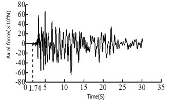
Fig. 5Time history curves
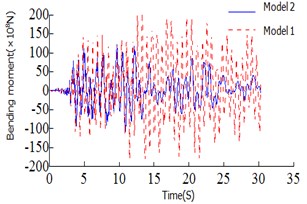
a) Bending moment of 2# tower bottom
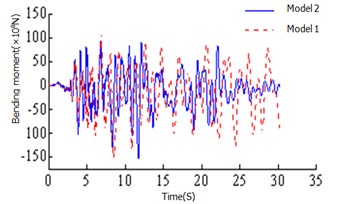
b) Bending moment of 1# tower bottom
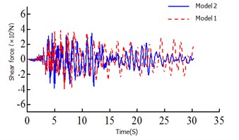
c) Shear force of 1# tower bottom
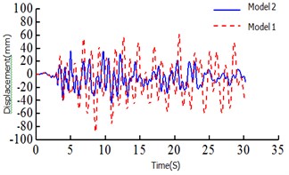
d) Beam end displacement of the 1# tower top
4. Optimization of safe-belt parameters
The parameters of the safe-belt connection device have a great influence on its mechanical properties. The control variable method is used to analyze the influence of the acceleration threshold , the safe-belt stiffness and Sliding force of safe-belt on the seismic response, which provides a reference for the application of the seatbelt ligation system.
4.1. Acceleration threshold
The acceleration threshold is the switch that the seatbelt connection device activates, and if the acceleration threshold is too small, it may be activated under non seismic loads such as wind vibration, rain vibration and nature vibration. If the acceleration threshold is too large, the safe-belt device cannot be activated when the earthquake arrives. Therefore, the acceleration threshold is crucial to the seatbelt connection device. In order to study the effect of the acceleration threshold on the seismic response of the safe-belt connection device, the range of the acceleration threshold is: 0.5, 1.0,..., 3.5, 4. The dynamic time-history analysis was carried out for the 8-cable-stayed bridge model corresponding to the acceleration threshold. The relationship of the maximum responses and acceleration threshold are shown in Fig. 6. It can be shown: 1) when the acceleration threshold is low, the earthquake arrives, the safe-belt is activated immediately, limiting the longitudinal displacement of the main girder, the damping effect is the best. 2) With the increase of acceleration threshold, the damping effect is decreased. When the acceleration threshold is increased to a certain value, the damping effect changes less.
Fig. 6Relationship of the maximum responses and acceleration threshold
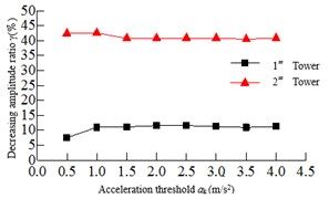
a) Tower bottom bending moment
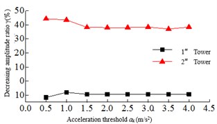
b) Tower bottom shear force
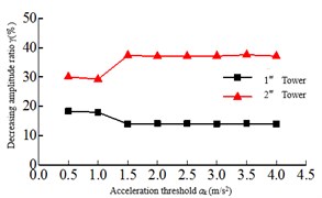
c) Tower top displacement
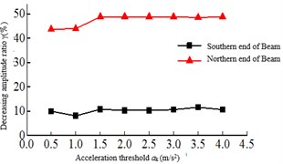
d) Beam end displacement
4.2. Safe-belt stiffness
The safe-belt stiffness refers to the longitudinal connection stiffness between the main girder and the lower beam. When the safe-belt stiffness is infinitely large, the connection between the tower and beam is equivalent to a hinged when the safe-belt is activated, and when the safe-belt stiffness is small, it can be understood that the tower and beam connection is elastic. Fig. 7 is the relationship between the maximum responses and the safe-belt stiffness. It shows that with the increase of the safe-belt stiffness, the damping rate of the internal force response of the 2# tower is increased, and the damping rate of the internal force of the 1# tower is reduced. When the increase to a certain value, the seismic response of the bottom of the bridge tower is smaller. As shown in Fig. 7(a), the damping rate of the tower bottom bending moment of the 2# tower is higher than 1# tower, and with the increase of the safe-belt stiffness, the damping rate of the tower bottom bending moment of the 1# tower and 2# tower is increasing.
Fig. 7Relationship of the maximum responses and safe-belt stiffness Kb
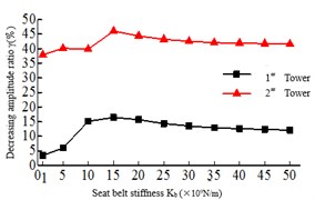
a) Tower bottom bending moment
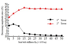
b) Tower bottom shear force
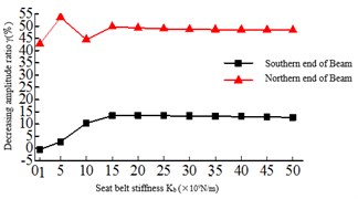
c) Beam end displacement
As shown in Fig. 7(b), the tower bottom shear force of the 2# tower is obviously higher than 1# tower, and with the increase of the safe-belt stiffness, the damping rate of the tower bottom shear force of the 2# tower decreases and the damping rate of the tower bottom shear force of the 1# tower increases. This is because the safe-belt device activates, the Twin Towers work together. In 1-15×109 N/m, the damping rate of beam end displacement is fluctuating, but after 15×109 N/m, the damping rate is stable at about 36 %.
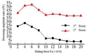
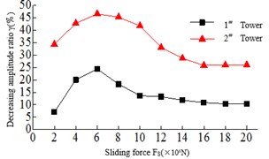
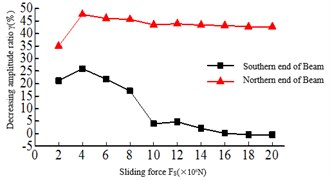
4.3. Sliding force of safe-belt
The Sliding force refers to the maximum longitudinal connected force between the main girder and the lower beam. When the tension of the safe-belt is more than the Sliding force, the safe-belt and the deadlock shaft can slip. From Fig. 8, it can be found 1) the tower bottom bending moment and shear force of the 2# tower are all larger than the 1# tower, and with the increase of the Sliding force, the tower bottom bending moment and the shear force damping rate of the Twin Towers show the trend of first increasing and then decreasing. When the Sliding force 6×10⁶N, the tower bottom bending moment and shear damping rate of the Twin towers are the highest. 2) The damping rate of the top tower displacement is changed when the sliding force 8×10⁶N, and the beam end displacement increases with the increase of the Sliding force.
Fig. 8Relationship of the maximum responses and sliding force
a) Tower bottom bending moment
b) Tower bottom shear force
c) Beam end displacement
5. Conclusions
The seismic response analysis and parameter analysis of the cable-stayed bridge with safe-belt constraint system are carried out under longitudinal seismic excitation, and the main conclusions and suggestions are given as follows:
1) Under the action of earthquake, the structural system of the double-tower cable-stayed bridge with safe-belt constraint system can be changed. So, the two towers can work in coordination, the responses of displacement at beam end and bending moment of the tower bottom can be well controlled.
2) The acceleration threshold of the safe-belt has little influence on the damping effect, but in engineering design, the value should not be too small.
3) The force transfer mode of cable-stayed bridges is affected by the value of the safe-belt stiffness, so the damping effect is also affected by it. But when it is greater than a certain limit, the damping effect is less affected.
4) The slip force of the safe-belt determines the maximum transfer force of the tower and the girder, which influences the seismic effect.
References
-
Fan Lichu Seismic Design. Tongji University Press, Shanghai, 1997.
-
Fen Linyun, Ye Aijun Study of application of seismic mitigation and isolation techniques to multi-span continuous girder bridges. Bridge Construction, Vol. 6, Issue 2005, p. 7-15.
-
Ye Aijun, Hu Shide, Fan Lichu Research on a seismatic structural system of cable-stayed bridge. Bridge Construction, Vol. 4, 2002, p. 1-4.
-
Denizen J., Snuffed C. F., Par Melee R. A. Seismic analysis of bridges on long piles proceedings of the american society of civil engineers. Journal of the Engineering Mechanics Division, Vol. 3, 1964, p. 223-254.
-
Xie Qunhua Effect analysis of constrained system on seismic performance of long-span cable-stayed bridge. Modern Transportation Technology, Vol. 3, 2016, p. 40-42.
-
Hu Qing An, Cui Gang, Liu Jian Xin Application of viscous damper to aseismatic design of cable-stayed bridge. Highway, Vol. 8, 2006, p. 77-80.
-
Yan Bin, Du Xiuli, Han Qiang, et al. Application of hybrid seismic mitigation and isolation device to seismic design of single-pylon cable-stayed bridge. Bridge Construction, Vol. 6, 2014, p. 101-106.
-
Zhang Wenxue, Li Jian Zhong, Li Huai Feng Study of seismic response characteristics of low gravity center cable-stayed bridge. Bridge Construction, Vol. 5, 2007, p. 21-23.
-
Zhang Wenxue, Wang Jingjing, Chen Shitong The influence of high of gravity on seismic response of cable-stayed bridges in different systems is studied. Highway, Vol. 1, 2015, p. 72-76.
-
Zhang Wenxue, Li Chenghua, Yang Jinbao Earthquake resistance of cable-stayed bridge with one tower of low gravity center. Journal of Shijiazhuang Tiedao University (Natural Science), Vol. 2, 2010, p. 88-93.
About this article

