Abstract
This article reviews trends and technologies used in current satellites’ development and launching technologies. Typical drives for attitude control mechanisms could be with: permanent magnets, reaction wheels or thrusters. These methods for attitude control in Orbit is slow or consumes a lot of power. For such tasks one of possible solutions of drive was represented. Some experiments were done and the results publicized in this article.
1. Introduction
Nowadays vital trend in satellites is to do more with low costs. An expression “Smaller, Cheaper, Faster, Better” is perfect example of satellites’ trends. Are a lot of benefits to use small satellites than bigger ones. When these satellites are merged to the clusters, which ones are called “swarms”, these networks will be more effective, more durable. Small satellites can communicate and solve dedicated exercises, merge their study results. Many challenges are investigating control applications, formation control, self-docking mechanisms in recent years. One of the biggest challenges for the satellite swarm are to define and control the orientations and positions of the satellites [1].
Nano satellites are small and has many restrictions for weight, size, computing capabilities. Precise navigation systems for nano satellites are very expensive and sometimes even impossible to integrate, but for their tasks such accurate systems for orientation and positioning are needed.
All satellites are exposed and working by various disturbances: aerodynamic torque, gravity gradient torque, magnetic torque and solar pressure moment. These moments are generally considered as external forces which makes some influences for satellite and stabilization for it. Nevertheless, some of the acting external torques can be used as stabilization or control moments by rational design [2].
2. CubeSats
Small satellites could be classified by different parameters: weight, orbit, purpose etc. Usually, small satellites are sub-categorized into these sections:
• Mini-satellite 100-500 kg (with fuel);
• Micro-satellite 10-100 kg (with fuel);
• Nano-satellite 1-10 kg (with fuel);
• Pico-satellite 100 g – 1 kg;
• Femto-satellite 10-100 g;
Most popular group of small satellites are CubeSats. They often are used for technology demonstration and science/education purposes. These satellites by common scaling system are treated like nano satellites.
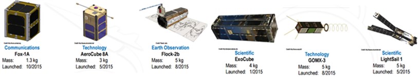
CubeSats have strict size, weight requirements. The requirements are specified by CubeSat program at the California Polytechnic State University. This standard describe size of CubeSat unit is 1U. It means, that it is 10×10×10 cm, and the weight not more than 1.33 kg. Iterative sizes of CubeSats are 1U, 2U, 3U and so on. These sizes mean that CubeSat changes their length, but not the height or the width. In Fig. 1 are shown few examples of CubeSats.
Almost all CubeSats missions are executed in low-Earth orbit or LEO. CubeSats are so small and with very limited size restrictions, there is not so much options what mechanisms and electronic could be installed on CubeSats.
This means that attitude control mechanisms must be effective, small, consume as less power as possible. It extends missions time allow equip nano satellites with measuring apparatus and other necessary mechanisms. Star or sun trackers are devices which helps for small satellites to find their orientation. For moving tasks must be mechanisms, which ones moves satellites sets proper directions, orientations [3].
Fig. 1Examples of nano satellites and CubeSats
3. Orientating axis and coordinate systems
Satellites must notice their own orientation and position. Necessary to select proper or acceptable coordinate system like a reference point, which will be used for investigation. If needed to define a system of coordinates for satellites or space applications, two key points must be achieved: decided with which coordinate system and with which reference point must be selected, also need to know the coordinate system’s center. These key points use the following three coordinate systems to define the attitude of a satellite: Body Frame, Orbit Reference Frame and Inertial Reference Frame.
The center of Body Frame coordinate system is set mass center of satellite and it is orientated according to satellite’s body. The coordinates which represents origin axis of Body Frame (, , ) is shown in Fig. 2. The coordinate system of reference object has represented by axis , , . These axes are located is set mass center of satellite and are orientated with the Orbit. The direction of axis vector pointing to fixed object i.e. center of Earth. The vector of is parallel with reference object vector. Finally, vector points to the direction of velocity vector if satellite’s orbit is circular. This coordinate system mostly is used for attitude maneuvers. The example of this coordinate system is shown in Fig. 2.
Fig. 2Attitude angles for satellites
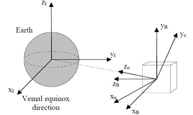
The coordinate system of reference object has its own center, related with the Earth’s center. The vectors of this system are named , , respectively. Vector is in the same direction as the North pole of Earth. The axis refers to Vernal Equinox direction. Vernal Equinox direction is used as the -axis for an astronomical reference system. This is a line, which intersects the Earth’s equatorial plane and the ecliptic plane, which is the plane of the Earth's revolution around the Sun. This reference object origin system basically used for Orbit analysis. The example of this attitude angles is shown in Fig. 2 [4].
4. Attitude control systems in CubeSats
Nowadays most popular method for attitude control of small satellites is magnetic control. Magnetic control method could be divided in two different methods: active (with electromagnets) and passive (with permanent magnets). These systems have big disadvantage magnetic torque acts only in one plane and this plane is perpendicular to the magnetic field vector. When magnetic control systems are used for attitude control, accuracy is 0.4-0.5 deg. It means that small satellites cannot be controlled precisely in space, when such magnetic controlling systems are used.
If passive control elements are used, permanent magnets or hysteresis rods are inserted into satellite’s chassis. It such case, a permanent magnet has a constant dipole it generates reinforce moments to align the magnetic axis with the Earth’s magnetic field. A hysteresis rods are made from conductive material, and can change magnetic dipole with the surrounding magnetic field. inextricable delay in this change imparts a dampening torque. When satellites are equipped with passive magnetic system, then it aligns and orientates it’s one of the axis with Earth’s magnetic field.
When active control systems are used, these systems apply electric current to coils. In these coils electromagnets creates active changes of magnetic dipole, which generates controlling moments. Fig. 3 shows how active coils could be integrated in satellite’s body.
Mostly, in satellite’s body frame for attitude control three rods are added and they are mounted orthogonally. These rods generate a magnetic dipole in any directions. Electromagnets can create different strength of magnetic field and this controls satellite’s orientation in space. Due requirements of strong Earth’s magnetic field, these systems are most efficient in Low Earth Orbit. All magnetic control system usually, will add total weigh about 200 g, and takes about 0.1U. It consumes about 250 mW of electric power.
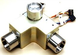
Other popular method for satellite’s attitude control is reaction wheels. The reaction wheels are common mechanisms in CubeSats for attitude control. Reaction wheels creates external mechanical moment by rotating a small wheel (relative to the size of the CubeSat) at a high rotation speed. The size of wheels and their sets are challenge to design and integrate in satellite’s chassis. These wheels consume more power and takes more volume in satellite. Usually, the system assembled from: wheels, motors, sensors, electronic units, mounts. Rotation wheels require at least 0,5U, the weight 700 g, and consume up to 2-3 W. The example of wheel unit shown in Fig. 4.
When exists requirements for accurate attitude control, combination of few methods could be used i.e., magnetic control mechanisms in pair with one reaction wheel, could be used for accurate three-dimensioning control.
Fig. 3Active coils location in CubeSat’s body
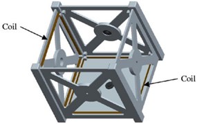
Fig. 4Set of reaction wheels for CubeSats
Last most popular system for attitude control - thrusters. The thrusters could not only attitude satellite, but also keep it desired position. When satellites are in LEO, primary disturbance forces appear. Lifetime of satellite is very limited, but with additional thrusters it could be extended. The power consumptions are huge, it almost equal with all system power consumptions combined. With thrusters is possible to perform both attitude control and orbit maneuvers [5].
5. Spherical magnetic drive
Knowing issues which have typical systems which are described above, new type of gear was invented. This gear is combined with two piezoelectric rings and inserted permanent magnet sphere between them. When electric current is applied, these piezoelectric rings deforming and rotates permanent magnet sphere is rotated. Controlling rotation angles, rotation speed is possible to get control of small satellite in space. This control method combines passive magnetic control system with modified reaction wheel system and uses piezoelectric rings for sphere’s control.
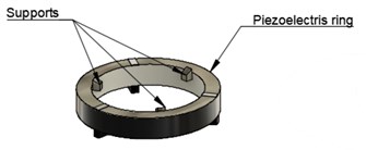
Mechanical side of this control system are consisting of: rotor (magnetic sphere which has north and south poles), this sphere is installed between two ring-shape piezoelectric transducers. Piezoelectric transducer has two electrodes on both opposite sides. One of this electrode is continuous and the other one – divided into three sections at every 120°. On that side, there the ring has divided sections, in inner side there are three support elements, where magnetic sphere is held by them. These supports are made from friction resistant material. On the other side of this piezoelectric ring there are other three supports elastic supports, they touch the flange. Fig. 5.
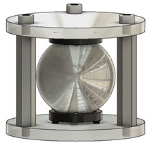
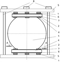
The system has the case, which is assembled from two flanges and three spacers. They close all mechanism, fixes all parts into positions and creates compact size drive. Isometric and schematic views of all system are shown in Fig. 6.
Fig. 5Schematic view of ring-shaped piezoelectric transducer: a) view from a magnetic sphere, b) opposite side view
a)

b)
Fig. 6Spherical magnetic drive: a) model view, b) schematic view: 1 – elastic supports; 2 – resistant-free support; 3 – magnetic sphere, 4 – piezoelectric transducers, 5 – flanges, 6 – sides of continuous electrodes of piezoelectric rings, 7 – sides of divided electrodes of piezoelectric rings, 8 – bolts
a)
b)
The system works following: continues electrodes of rings are connected together, and then connected to the ground. Divided electrodes are connected together (top and bottom rings) and then they are connected to three-phase generator (A, B and C phases). When electric current is applied for one segment, piezoelectric ring will have 3D deformations. If two electrodes (segments) from bottom ant top ring are connected and electric current is applied these piezoelectric rings deforms in elliptic shapes and it spins the magnetic sphere. If all electrodes (segments) are connected to reprehensive phases A, B and C and at the same time electric current are applied to these phases (, ir , then “running wave” will appear and it turns magnetic sphere. Because electric phases could be controlled, it allows to control that “running wave” and at the same time, the direction of rotation can be controlled. Such system is very compact, could be integrated in small volumes, and consumes small amounts of energy and could be used for such applications like attitude control of small satellites. Also, such system is precise and allows control SatCubes accurate.
6. Experiments
Initial experiments to determine resolution piezoelectric 3D motor with spherical rotor were carried on with experimental setup, shown in Fig. 7. Results are shown in Fig. 8, where harmonic burst type signal of the frequency 92.1 kHz and amplitude 60 V were applied to the electrodes of piezoelectric transducer and output angular displacement were measured by Polytec Laser Doppler Vibrometer OFV5000/512.The aim of experiments was to prove feasibility of this type of a drive for such kind of accurate rotation, repeatability, and possibilities to use such drives for operations like attitude control, taking into consideration its low cost and simple design and benefits which this drive could achieved.
Fig. 7Experimental setup: 1 – spherical magnetic drive, 2 – controller, 3 – Polytec Laser Doppler Vibrometer system OFV512/5000, 4 – linear amplifier EPA-104, 5 – signal generator Agilent 33220A, | 6 – oscilloscope PicoScope 3424, 7 – PC with a PicoScope and Polytec software
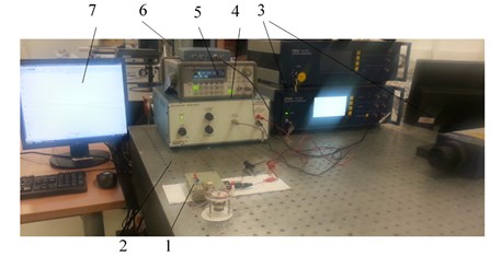
Fig. 8The example of step angular displacements obtained with burst type vibrations of the piezoelectric motor at operational frequency 92.1 kHz
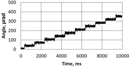
Fig. 9The example of setup for impedance analysis: 1 – Wayne Kerr 6500B impedance analyzer, 2 – piezoelectric deflector of the magnetic sphere
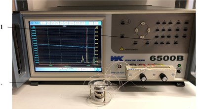
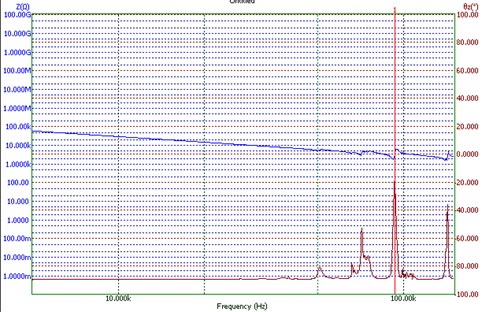
Other experiments were measuring impedance. Three different segments were applied to current with changeable frequency. These experiments were done with Wayne Kerr 6500B impedance analyzer Fig. 9. The results shown in Fig. 10.
Fig. 10Analysis for first segment (peak at – 93.11 kHz)
7. Conclusions
A new 3D piezoelectric deflector of the magnetic sphere was developed like possible apparatus for attitude control in Orbit for small satellites. The scheme of a piezoelectric drive is presented; its feasibility and advantages are discussed. This drive is compact, uses small amounts of power and can orientate the satellite in desired position. Also, this drive could be used for attitude control and relatively fast position or orientation change in the Space.
Some experimental results are presented. A resolution of angular displacement of 30 µrad of the magnetic sphere are measured using Polytec Laser Doppler Vibrometer. An operational frequency of 93.11 kHz of the piezoelectric drive was determined using Wayne Kerr 6500B impedance analyzer.
References
-
Kang B., Lee J., Won C. Micro-Navigation Sattelite network Design and Analysis. 2010, https://www.temple.edu/csnap/publications/iongnss%20draft6.pdf.
-
Wang P., Zheng W., Hongo H., Wu J. Attitude Control of Low-Orbit Micro-Sattelite with Active Magnetic Torgue and AeroDynamic. 2010, http://digitalcommons.usu.edu/cgi/viewcontent.cgi ?article=1492&context=smallsat.
-
Nguen T., Cahoy K. Laser Beacon Tracking for Free-space Optical Communication on Small Satellite Platforms in Low-Earth Orbit. 2015, http://ssl.mit.edu/files/website/theses/SM-2015-NguyenTam.
-
Bedington R., Truong Ca E., Tan Y. C., Cheng C., Durak J., Larsen D., Grieve J., Oi D., Ling A. Deploying quantum light sources on nanosatellites II: lesions and perspectives on CubeSat spacecraft. 2015, https://arxiv.org/pdf/1508.07074.pdf.
-
Berner R. Control Moment of Gyro Actuator of Small Satellite Applications. 2005, https://www.google.lt/url?sa=t&rct=j&q=&esrc=s&source=web&cd=2&cad=rja&uact=8&ved=0ahUKEwie3uK774rSAhVGDMAKHQYpAFEQFggdMAE&url=https%3A%2F%2Fscholar.sun.ac.za%2Fbitstream%2Fhandle%2F10019.1%2F2144%2Fberner_control_2005.pdf%3Fsequence%3D1&usg=AFQjCNEjcXB6KyLzN9Niy1IeRGhQVWC4gQ&sig2=EqGnyTwo01NsGWfl1M7s-A&bvm=bv.146786187,d.ZGg.
About this article

The work was supported by the Research Council of Lithuania under the Project No. MIP-084/2015 “SmartTrunk”.
