Abstract
This paper presents results on the development and investigation of new miniature robots with increased number of degrees of freedom, based on the application of piezoelectric kinematic pairs with multi-DOF. The schematics of technologically advanced multi-DOF active kinematic pairs are presented and the details of their control are explained. The structure control of multi-DOF active kinematic pairs is based on sectioning of electrodes of the piezoelectric actuators and allows selecting desirable types of oscillations and speeds of links. Three modifications of piezoelectric robots with 6 and 15 DOFs are provided, together with their resolutions and responses to step inputs. Modal and harmonic analyses were performed and displacements of contact points were obtained. Trajectory planning algorithms are developed based on the numerical results.
1. Introduction
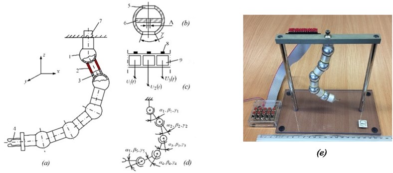
The first piezoelectric robot was patented in USSR in 1980 by R. Bansevicius and K. Ragulskis [1], but owing to the imposed ban (“not to be published in open press”), further developments were postponed until 1989, when two piezoelectric robots with 6 and 9 DOFs were developed in Kaunas University of Technology and used as teaching aids for students (Fig. 1). The robots consisted of 2 (Fig. 1(a)) and 3 (Fig. 1(b)) Class III kinematic pairs, which were controlled by applying harmonic voltage to sectioned electrodes of piezoelectric transducers in the form of a cylinder or disc.
Fig. 1First piezoelectric robots developed in Kaunas University of Technology in 1989
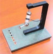
a) Six DOFs
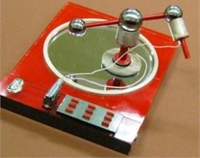
b) Nine DOFs with positioning system on the plane
In 1996, a paper was published in IEEE Transactions on Industrial Electronics, introducing the term Piezomechanics as a subsystem of Mechatronics [2] and defining more precisely the scope and possible applications of piezoelectric robots. In 2001, patents were obtained (R. Bansevicius and S. Ahmed, US Patent 6262514; GB Patents 2 332 090 and 2 331 398); the concepts were based on the elimination of various errors introduced by piezoelectric robots and reducing their dimensions.
In [2], the concept of active kinematic pair was introduced, that plays an important role in various mechatronics devices and piezoelectric robots. A kinematic pair becomes active, when one or two of its links are made from smart materials (piezoelectric, magnetostrictive, material with memory, etc.), and we can control its motion by supplying energy to specific zones of the links. An important feature is its ability to control the structure of the system, including the number of DOFs of the mechanical components, which is achieved by controlling the friction forces down to zero value or generating static or quasi-static displacements or stresses in elastic bodies. Another important factor is the structure of a system, which can be changed in a very short time, depending on the natural frequencies of the dynamic system. Active kinematic pairs transform high-frequency mechanical oscillations into continuous or stepped motions and when required, achieve touch, slip, and inner force sense for sensory-controlled devices.
After the year 2000, many papers [3-7] devoted to various aspects of application of piezoelectric transducers, mainly with 1 DOF, appeared. Some were dealing with manipulating objects in a plane [3]; the scientific interest in this area is constantly growing. We will consider here piezoelectric active kinematic pairs, as having important applications in piezoelectric robots. They can be of 5 DOFs (Class I) to 1 DOF (Class V). Figs. 2, 5 show only new technologically advanced piezoelectric active kinematic pairs aimed at robotics applications.
2. Technologically advanced multi-degree-of-freedom active kinematic pairs
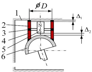
Kinematic pair with 3 DOFs. Examples of Class III 3-DOF piezoelectric active kinematic pairs with controllable structure are shown in Fig. 2. Here, the spherical ferromagnetic surface 1 (Fig. 2(a)) (or hollow sphere to save weight) is in contact through three contacting high-friction elements 2 with the piezoelectric radially poled cylinder 3. The contact between the spherical surface and piezoelectric cylinder is ensured by the permanent magnet 4, mounted with a gap . Electrodes on the external surface of the piezoelectric cylinder are sectioned into 3 parts, forming exciting zones 5, 6, and 7. Connecting a resonant frequency harmonic voltage to any of these zones (e.g., ; 0; 0; where is the resonant frequency of a higher mode of oscillation of piezoelectric cylinder) leads to rotation of sphere around the axis corresponding to the position of a specific exciting zone. Connecting three-phase harmonic voltages to electrodes, e.g., ; (); (), leads to rotation of the link 1 around the axis.
Fig. 2Class III 3-DOF piezoelectric active kinematic pairs with controllable structure and spherical passive link
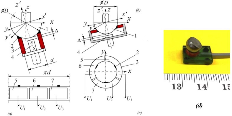
This type of Class III 3-DOF piezoelectric active kinematic pair with controllable structure can also be achieved using a disc type piezoelectric transducer with axial poling (Fig. 2(b)).
Fig. 2(d) shows a picture of a 3D high-resolution miniature laser deflecting device for space applications, based on a similar scheme.
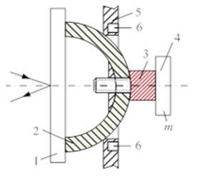
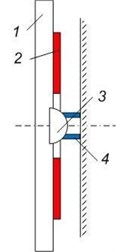
This type of kinematic pair can be designed with both links made passive. In Fig. 3(a), oscillations of the sphere are generated with the help of an external piezoelectric transducer, oscillating in 2D (bending oscillations); in Fig. 3(b), a piezoelectric transducer with sectioned electrodes is fixed on a 2D deflecting object (e.g., mirror). This concept is illustrated in the design of a 1-DOF laser beam deflector (Fig. 3(c)), where the mirror is mounted on two ferromagnetic spheres, rotated in cylindrical magnets.
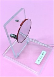
Fig. 3Class III 3-DOF piezoelectric active kinematic pairs with controllable structure and spherical passive link: a) laser deflecting device with mirror 1, passive ferromagnetic sphere 2, piezoelectric transducer 3, passive mass 4, passive link 5, permanent magnet 6; b) laser deflecting device with mirror 1, piezoelectric transducer 2, passive ferromagnetic sphere 3, permanent magnet 4 in the form of cylinder; c) photograph of laser deflecting device
a)
b)
c)
Fig. 4Class III 3-DOF piezoelectric active kinematic pairs with controllable structure
a)
b)
c)
d)
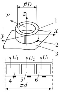
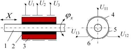
An active kinematic pair with 3 DOFs on a plane is made in the form of a piezoelectric cylinder 1 with radial poling (Fig. 4(a)), contacting with the help of three high-friction contacting elements 2 with the plane 3. The external or internal electrodes of the piezoelectric cylinder are sectioned into 3 symmetrical parts 4, 5, and 6 and are connected to the harmonic signal generator , where 1, 2, 3. When cos , 0, and 0, it leads to displacement of the piezoelectric cylinder along the axis corresponding to the position of the specific exciting zone. A very similar schematic is shown in Fig. 4(b), where the piezoelectric transducer is created in the form of a piezoelectric disc resting on three contacting elements and the contact between them and the plane is ensured by a permanent magnet 7.
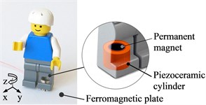
It is worth mentioning that this type of kinematic pair is technologically advanced and allows developing high-speed 3D positioning on a plane. Fig. 4(c) shows a miniature simple robot, consisting of a piezoelectric transducer in the form of a piezoelectric cylinder with an external diameter of 8 mm and height of 6 mm, with 3 groups of sectioned electrodes. The maximum speed of positioning on a plane was 85 mm/s, when the harmonic voltage supplied to its electrodes was 75 V. A small piezoelectric cylinder (6 mm diameter) was applied to actuate a LEGO figure in 3D (Fig. 4(d).
An active kinematic pair with 2 DOFs is made in the form of a passive rod 1, contacting through bush 2 with a piezoelectric cylinder 3 with radial poling (Fig. 5(a)). The electrodes of the piezoelectric cylinder are sectioned into three zones, left and right, each one having three sections 4, 5, and 6, and circular electrode placed between them. Initially, the gap between rod 1 and bush 2 is equal to zero; it is controlled by applying a voltage V to the circular electrode, changing the diameter of the piezoelectric cylinder. The type of displacement of the rod depends on the connection of electrodes to the harmonic signal generator. Translation is achieved by connecting to , , and (or , , and , when reverse is activated). Rotation is achieved by connecting to electrodes In case of reversed rotation, the phase is reshuffled: .
Fig. 5Class IV 2-DOF piezoelectric active kinematic pair
This type of kinematic pairs can attain two types of motions, i.e., a) longitudinal and b) oscillation mode, when there is a small difference between the frequencies of oscillation of both links (beats). Oscillatory mode is very convenient for robot grips, particularly when the robot is used to assemble mechanical parts. The advantages of these kinematic pairs when used in robotics are as follows: a) unlimited angular resolution and maximum angular displacement, b) high response time, c) low power consumption, and d) no magnetic fields generated. Additional functions can be performed: self-diagnostics, multi-functionality, adaptive features, self-assembly.
It is possible to implement two levels of DOF of an active kinematic pair. The first level comprises large deflections produced by the transformation of resonance vibrations of a pair’s links into continuous motion. The second level deals with small deflections (from hundreds to a nanometer range) implemented by means of inverse piezoelectric effect and sectioning of electrodes. Such advantages have made piezo actuators very popular in precision mechanics, mechatronics and robotics, optics and measurement systems, etc.
3. Schematics of miniature piezoelectric robots
Fig. 6 shows the general schemes of two modifications of piezoelectric robots with 6 DOFs. In the first modification (Fig. 6 (a-c, e)), the contact force between spheres 1 and 4 and piezoelectric transducers 2 and 3 is created with the help of permanent magnet 6. In the second modification (Figs. 6 (d, f)) the same function is performed with the help of spring 8, with its ends fixed at the centers of spheres. This feature allows a significant reduction of the weight of the robot, leading to a faster response time.
Some results of experimental investigations of robots is shown in Fig. 7. Impedance-phase vs. frequency characteristics were measured with the help of the impedance analyzer Wayne Kerr 6500B (Wayne Kerr Electronics Inc., USA).
Fig. 6Two modifications of a piezoelectric robot: 1 and 4 – ferromagnetic spheres, 2 and 3 – piezoelectric cylinders with radial poling, 5 – grip, 6 – permanent magnet, 7 – contacting element made of high-friction material, 8 – spring
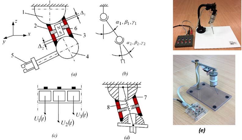
Fig. 7Frequency response of impedance of piezoelectric transducer 2 (Fig. 6(a)); operational frequency is 64 kHz
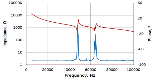
Fig. 8One step of a robot measured at the grip (Fig. 6(a)), when activating: a) actuator 2; b) actuator 3
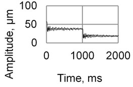
a)
b)
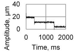
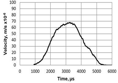
The resolution and velocity of displacement of the robot (Fig. 6(a)) generated using burst type electric signal ( 60 V, 64 kHz) was measured at the grip using a laser vibrometer system OFV-5000/505 (Polytec Inc., USA) and are shown in Fig. 8 and Fig. 9.
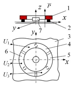
Another version of the miniature piezoelectric robot is shown in Fig. 10. Despite its simple design, the robot has 6 DOFs and by connecting the harmonic voltage , , or to the electrodes of transducer 2, it is possible to move the robot on plane 1 (3 DOFs). Moreover, by connecting voltage , , or to the electrodes of transducer 4, it is possible to rotate the grip (3 DOFs). Fig. 10(c) shows the experimental model of a robot with 6 DOFs; here piezoelectric cylinder 2 was replaced with a hemispherical piezoelectric transducer, contacting with the plane in three points.
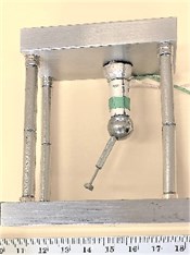
An experimental device to test the feasibility and maximum 3D deflection of joints of a piezoelectric robot with 15 DOFs is shown in Fig. 11. To ensure the contact force between active links and spheres, a flexible wire was used; its tension was controlled by a special device. To reduce the weight of the robot, hollow spheres were applied. Initial experiments show the feasibility of the technical concepts; however, the importance of high rigidity to the robot resolution is stressed.
Fig. 9Displacement a) 1 and b) velocity of a robot, when burst type electric signal 2 (U1= 60 V) is connected to the electrodes of the piezoelectric actuator
a)
b)
Fig. 10Miniature piezoelectric robot: 1 – ferromagnetic plane, where 3D positioning is attained; 2 – piezo active cylinder with radial poling and three sectioned electrodes; 3 – layer of passive material, insulating oscillations of piezo active cylinder 2 to another piezo active cylinder 4; 5 – permanent magnet, ensuring the initial axial forces; 6 – ferromagnetic sphere; 7 – electrodes of piezoelectric transducers 2 and 4; 8 – contacting elements
a)
b)
c)
4. Numerical analysis of a cylindrical piezoelectric actuator with sectioned electrodes
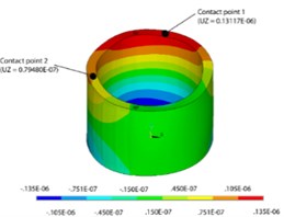
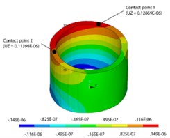
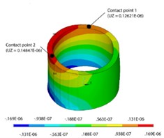
The cylindrical actuator with sectioned electrodes was used in many miniature high-resolution piezoelectric robots (Figs. 2, 4(a), 5, 6(a), 10(b), and 11(c)). A numerical analysis of the cylindrical actuator was performed using ANSYS software. The actuator is a piezoelectric cylinder with an external diameter of 33 mm, internal diameter of 28 mm, and height of 21 mm. It has sectioned electrodes for motion generation. A piezoceramic element PZT-4 was chosen, owing to its suitable properties such as low dielectric losses and high resistance to depolarization. Modal analysis showed that the required form exists at 61.721 Hz, which is very close to the working frequency obtained experimentally (65 kHz). This form ensures that major displacements occur towards the direction.
Fig. 11Robot with 15 DOFs: device to test the feasibility and maximum 3D deflection of joints: 1 – hollow sphere; 2 – piezoelectric radially poled cylinder with 3 groups of sectioned electrodes; 3 – passive bush; 4 – grip; 5 – hole in sphere, limiting 3D rotations of the piezoelectric cylinder; 6 – centering insert; 7 – tension control device; 8 – contacting pads; 9 – electrodes of a piezoelectric transducer; αi, βi, and γi – link deflection angles; ∆ – hole diameter
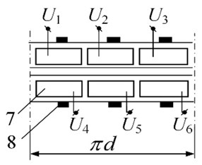
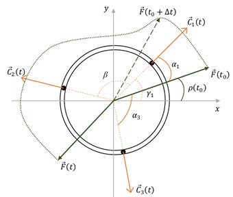
The chosen electrode scheme consists of three identical electrodes, each placed at 120°. Two high-frequency signals, and , are applied to the sectioned electrodes and generated oscillations are further passed through the contact point. If only one electrode is excited, then the cylinder motion is passed through the contact point positioned in the middle of an electrode segment. In case when two electrodes are excited, the motion force is accumulated and the highest displacements are between the contact points (Figs. 13(a-c)). In order to obtain the required motion (trajectory planning), different voltages are applied to the electrodes, yielding different results as shown in Fig. 12.
The force that is required for the proper motion was determined in [8]. Excitation zones of the cylinder must be simultaneously active with different force values of contact points for a resultant force calculation [8]. Force values are obtained from harmonic analysis, where the movements of contact points are known; therefore, it is possible to calculate cumulative displacement vectors. The main task of the mathematical modeling is to calculate the length of the vectors in the time domain, when the length and direction of the force vector are given. The motion vector starting coordinates (, , ) are the coordinates of contact points when the cylinder is not excited. The end coordinates are obtained using displacements:
And the resultant force vector is obtained (Fig. 13) through simple algebraic operations (1) and (2):
Fig. 12Harmonic analysis results: a) deformations when U1= 100 V and U2= 50 V, b) deformations when U1= 100 V and U2= 75 V, c) deformations when U1= 100 V and U2= 100 V
a)
b)
c)
Fig. 13Scheme of total force F→(t) and its components C→jt acting at contact points, where j is the electrode number
The numerical results of the displacements of contact points are presented in Table 1. The largest displacements occur towards the direction and the direction of motion vectors can be.
Table 1Displacements of contact points
Contact point number ( / ) | |||
1 (100 V/50 V) | –0.84773E-08 | –0.21495E-07 | 0.13117E-06 |
2 (100 V/50 V) | 0.24534E-07 | 0.12221E-07 | 0.79480E-07 |
1 (100 V/75 V) | –0.96413E-08 | –0.20400E-07 | 0.12869E-06 |
2 (100 V/75 V) | 0.29914E-07 | 0.13872E-07 | 0.11398E-06 |
1 (100 V/100 V) | –0.10805E-07 | –0.19305E-07 | 0.12621E-06 |
2 (100 V/100 V) | 0.35294E-07 | 0.15523E-07 | 0.14847E-06 |
5. Conclusions
An overview on state-of-the-art piezoelectric robots are presented together with the most technologically advanced piezoelectric adaptive kinematic pairs. Two modifications of piezoelectric robots with 6 DOFs are presented with their impedance, resolution, and reaction to burst of harmonic signals. The scheme of a piezoelectric robot with 15 DOFs is presented; its feasibility and advantages/disadvantages are discussed. The obtained displacements of contact points allowed the calculation of the cumulative displacement vector and the determination of the appropriate signal ratio between electrodes. The trajectory planning algorithms are developed based on the numerical results.
References
-
Bansevicius R., Ragulskis K. Piezoelectric Actuator for Micromanipulator. USSR Patent 932721, B25J 7/00, Cl.3, 1980.02.26, (in Russian).
-
Bansevicius R., Parkin R., Jebb A., Knight J. Piezomechanics as a subsystem of mechatronics: present state of the art, problems, future developments. IEEE Transactions on Industrial Electronics, Vol. 43, Issue 1, 1996, p. 23-29.
-
Chi Hsiang Pan Novel mobile piezoelectric micro robots driven by traveling wave. International Conference on Manipulation, Automation and Robotics at Small Scales, 2016.
-
Bergander A., Driesen W., Varidel T., Breguet J.-M. Monolithic piezoelectric actuators for miniature robotic systems. Actuator, Bremen, Germany, 2004.
-
Breguet J.-M., Pernette E., Clavel R. Stick and slip actuators and parallel architectures dedicated to microrobotics. Proceedings of the SPIE, Vol. 2906, 1996, p. 13-24.
-
Hariri H. H., Soh G. S., Foong S. H., Wood K. L., Otto K. Miniature piezoelectric mobile robot driven by standingwave. The 14th IFToMM World Congress, Taipei, Taiwan, 2015.
-
Pan C. H., Sz Sheng Tzou, Ruei Yang Shiu A novel wireless and mobile piezoelectric micro robot. Proceedings of the IEEE International Conference on Mechatronics and Automation, China, 2010, p. 1158-1163.
-
Bansevičius R. P., Drukteinienė A., Jūrėnas V., Kulvietis G., Mažeika D. Fine trajectory planning method for mobile piezorobots. The 12th International Workshop on Piezoelectric Materials and Applications in Actuators), Lithuania, 2015.
Cited by
About this article

The work was supported by the Research Council of Lithuania under the Project No. MIP-084/2015 “SmartTrunk.”
