Abstract
Accuracy of laser optical beam steering strongly depends on dynamic characteristics of the positioning mechanism of the mirror. Novel design of the beam steering mirror with an integrated piezoelectric active kinematic pair is introduced in the paper. Rotation mechanism of the mirror has a simple design and allows achieving nano-scale resolution. Rotation of the mirror is achieved by exciting harmonic vibrations in the special clamping mechanism. Plate type piezoelectric transducer is used to generate vibrations. Two different electrode patterns and excitation schemes of the actuator are analyzed. Numerical modelling was performed to confirm operating principle of the rotation mechanism. Experimental prototype of the piezoelectric mirror was made and corresponding measurements were performed. Results of numerical and experimental studies are discussed.
1. Introduction
Laser optical systems are widely used for the different industrial applications such as laser welding, cutting, drilling, printing [1, 2]. Lasers also are used for the measurement equipment, medical and scientific applications [3-5]. Ability to adjust the laser beam pointing is crucial for optical system. Beam needs to be moved in position and angle therefore different optomechanical elements including mirrors are used. A beam steering mirror and a beam capture mirror are usually disposed along an optical pathway. A controller moves and rotates the beam steering mirror to project the beam to a target location on a surface. Positioning systems are generally electrically driven and have feedback systems to assess target pointing [6].
Accuracy of the laser beam steering strongly depends on the characteristics of the rotation system. Rotation speed, maximum rotation angle, spatial resolution, stabilization and number of degrees of freedom are the key features of the beam positioning system. There are many different positioning systems of the mirror developed till now [3]. Operating principle of these systems can be divided into electro-mechanical and piezoelectric. Most of industrial laser optical systems use different type electrical motors to rotate or move the mirrors, however accuracy of such systems are limited till several micrometers [1]. There are also report on beam-steering system that use flexible hinges technology to achieve the required functionality [7]. Hinges are actuated by piezoelectric stacks for precise beam positioning. Piezoelectric mirror for one and two dimensional operation using bimorphs with both clamped ends have been developed [8, 9]. It has a large deflection, a simple construction and micrometer scale resolution.
Different types of piezoelectric motors can be used to rotate the mirror: traveling wave, standing wave ultrasonic motors, and inertial type motors [10]. Advantages of piezoelectric motors are large torque, simple design and nano-scale resolution, therefore mirrors with different diameter and mass can be rotated very precisely [11]. One or two degrees of freedom beam steering mirrors can be developed employing multi degree of freedom piezoelectric actuators [12].
Novel design of piezoelectric mirror is presented in the paper. Rotation of the reflector is achieved by exciting elliptical type vibrations in the hinges of the mirror. Such principle of the rotation allows to achieve very simple design and to reduce manufacturing price. Proposed design of piezoelectric mirror also allows manufacturing high precision and milli-size positioning devices.
2. Design concept and operating principle
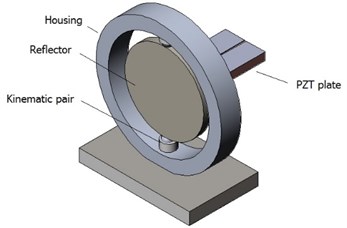
Single degree of freedom piezoelectric mirror is investigated. Principle scheme of the mirror is presented in Fig. 1(a). Piezoelectric mirror consists of the three main parts: specular reflector, piezoceramic plate and housing. Piezoelectric plate is glued in the backside of the reflector and is used to excite resonance vibrations of the reflector.
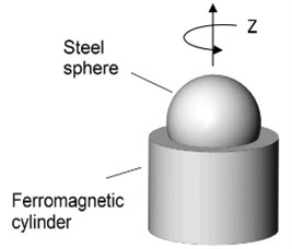
Two ferromagnetic spheres and magnetic cylinders are used for the deflector clamping. Ferromagnetic spheres are rigidly bonded at the edges of the reflector while cylinders are fixed in the housing. Angle between bonded spheres is equal to . The spheres and cylinders contact each other because of the magnetic force between them. Such clamping mechanism is not rigid type so mechanical vibrations of the reflector can be transferred into continues rotation of the reflector because of the friction force between the ferromagnetic sphere and the cylinder. This type of clamping system allows achieving nano scale rotation of the reflector about vertical axis.
Fig. 1a) Principle scheme of piezoelectric mirror and b) the active kinematic pair
a)
b)
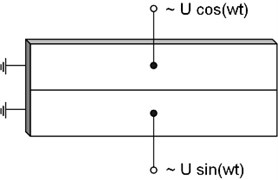
First bending mode of the piezoceramic plate vibrations is employed to rotate the reflector. Plane of the plate vibrations and plane of the elliptical motion of the contacting points are perpendicular to the axis of reflector rotation. Electrodes of the piezoceramic plate are divided in two equal sections as shown in Fig. 2. Electrode pattern is symmetric therefore clockwise and counterclockwise motion of the contacting points of the ferromagnetic sphere can be excited at the same excitation frequency and rotation of the reflector can be obtained in both directions. Two excitation schemes can be used to excite vibrations of the piezoceramic plate. The first excitation scheme uses one harmonic signal (Fig. 2(a)). The direct and reverse elliptical motion of the contacting points is achieved by interchanging excited electrode. The second excitation scheme uses two harmonic electric signals with phase difference of 2 (Fig. 2(b)). The direction of elliptical motion of the contacting points is changed by counterchanging channels of the electrical signals between electrodes.
Fig. 2a) Two excitation schemes of the electrodes: one signal scheme, b) two signals scheme
a)
b)
Let’s analyze displacements of the points located at the right side of the piezoceramic plate (Fig. 3). Assuming the reflector is stiff enough, the motion of the point is the same as the motion of contacting points located on the sphere of the active kinematic pair.
Fig. 3Motion analysis of the piezoelectric plate
Displacements of the points located at the right side of the piezoceramic plate can be decomposed into vertical and horizontal components and respectively and can be written as follows:
where and are vibration amplitudes of the middle point in and directions, and are angular frequency and phase, is the distance of the analyzed point from the middle line of the plate and is time. Value of the phase is within interval and depends on the excitation scheme of the electrodes. If 0, then points has linear displacement. If then the relation between and can be derived as:
This case represents electrodes excitation scheme showed in Fig. 2(b). It can be noticed that the trajectory of the points are the ellipses. In order to change the direction on the motion, the phases of excitation voltage must be counterchanged.
3. Numerical modeling and results
The finite element modeling was used to perform modal frequency and harmonic response analysis and to calculate trajectories of the contact points motions under two excitation regimes of the piezoelectric plate. Basic dynamic equations of the piezoelectric mirror are derived from the principle of minimum potential energy by means of variational functional and can be written as follows [13]:
where , , , , are matrices of mass, stiffness, electroelasticity, capacity and damping, respectively; , , , are, respectively, vectors of nodes displacements, potentials, external mechanical forces and charges coupled on the electrodes.
FEM software ANSYS was used to build a three dimensional finite element model of the piezoelectric mirror and to run a simulation. The finite element model contains reflector and the piezoceramic plate. Analyzed contact point is located on the top of reflector. Following materials were used for simulation: aliuminium D16 was used for the reflector and PZT-8 was used for modelling the piezoceramic plate. Properties of the materials are given in Table 1.
Table 1Properties of the materials
Material properties | Piezoceramic PZT-8 | Aluminum D16 |
Young’s modulus [N/m2] | 7.2×10¹⁰ | |
Poison’s ratio | 0.3 | |
Density [kg/m3] | 7600 | 2770 |
Permitivity, ×10-7 [F/m] | 11.42; 8.85 | |
Piezoelectric matrix [C/m2] | –18.01; 29.48; 10.34 | |
Elasticity matrix, ×1010 [N/m2] | 14.68; 8.108; 8.105; 13.17; 3.29; 3.14 | |
Dimensions of the reflector and the plate were as follows: Ø32×3 mm and 30×16×3 mm respectively. No mechanical clamping was applied in the model. Damping was evaluated in the model by introducing the mechanical loss factor for piezoceramic plate and the isotropic loss factor of the reflector. The mechanical loss factor was set to 0.004 and the isotropic loss factor was equal to 0.001. Piezoelectric and dielectric losses were neglected in the model.
Modal-frequency analysis of the mirror was performed. While analyzing the results of resonant oscillation modes, it was determined that the oscillation mode at 30.50 kHz has dominated first bending mode of the piezoceramic plate and can be used for further investigation (Fig. 4).
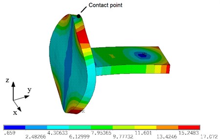
Fig. 4. Modal shape of the mirror at 30.50 kHz
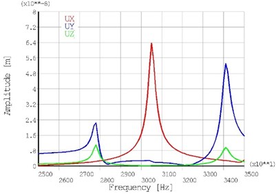
Harmonic response analysis was performed with the aims to find out the mirror response to sinusoidal voltage applied on electrodes of the piezoceramic plate and to calculate trajectories of the contact point. Two excitation schemes were used in simulations as shown in Fig. 2. A 50 V AC signal was applied to the electrodes. A frequency range from 25 kHz to 35 kHz with a solution at 100 Hz intervals were chosen and adequate response curves of contact point oscillation amplitudes were calculated. The results of calculations are given in Fig. 5 where the contact point’s amplitude versus frequency are given. Graphs of the contact point oscillation amplitude show that the excitation frequency at 30.5 kHz has a local peaks of amplitude component in both excitation cases. The 0.064 µm and 0.091 µm vibration amplitudes were obtained for displacement components when the first and the second excitation case of the electrodes were used respectively.
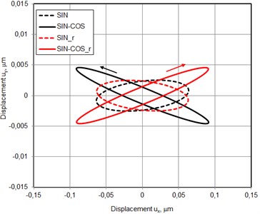
The trajectories of the contact point motion were calculated at the frequency 30.50 kHz (Fig. 6). Four excitation regimes of piezoceramic plate were used. Using first excitation scheme sine signal was applied on the first electrode and after that on the second electrode (Fig. 2(a)). Sine – cosine and cosine – sine schemes was applied on the electrodes for the second excitation scheme (Fig. 2(b)).
While analyzing the trajectories of the contact point motion, it can be noticed that they have ellipsoidal shapes. It confirms an analytical formulation of the operating principle. The lengths of the major axes of the ellipses are 0.13 µm and 0.18 µm, when the first and the second excitation scheme is used respectively. It must be mentioned that length of the ellipses major axes are the same for forward and backward rotations.
The lean angles to coordinate axis are 5.8° and 174.2° for the clockwise and counterclockwise rotation, respectively when the first excitation scheme is used and 11.3° and 168.7° for the second excitation scheme. It must be noticed that the contact point moves in different directions when switching between electrodes excitation regimes is applied. It confirms that two directional rotation of the mirror will be achieved. Based on the results of the numerical simulation it can be concluded that the operating principle of the mirror is validated. The mirror will produce bidirectional rotation at the 30.5 kHz excitation frequency.
Fig. 5The amplitude – frequency characteristic of the contact point oscillation when the first a) and second b) excitation scheme of the electrodes are use
a)
b)
Fig. 6Trajectories of contact point motion
4. Experimental investigation
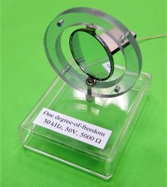
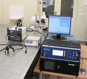
A prototype piezoelectric mirror was made for experimental study (Fig. 7(a)). The goal of experiment was to validate operating principle of the piezoelectric mirror and to verify results of numerical modelling. Operating principle of piezoelectric mirror was validated by investigating rotational motion of the reflector. Experimental setup consisted of signal generator Agilent 33220A, amplifier EPA-104, laser displacement sensor with controller Polytec OFV-512, vibrometer Polytec OFV-5000, ADC PicoScope-3424 and personal computer (Fig. 7(b)).
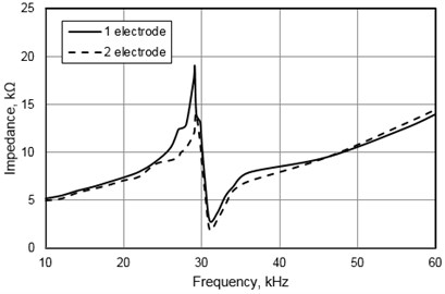
The impedance-frequency characteristic of the piezoelectric mirror was measured with the help of the impedance analyzer Agilent 4294A at 10 mVrms. Results of the impedance measurements of the first and second electrode are given in Fig. 8. The curve valley position indicates that the resonant frequency is 29.1 kHz. Relative error between measured and calculated resonant frequency is 4.5 %. The errors mainly came from FEM simulation, such as the inaccuracy of the material properties, neglecting glue layer between reflector and the piezoceramic plate.
Fig. 7a) Prototype piezoelectric mirror and b) experimental setup
a)
b)
Fig. 8Measured impedance of the piezoelectric mirror versus frequency
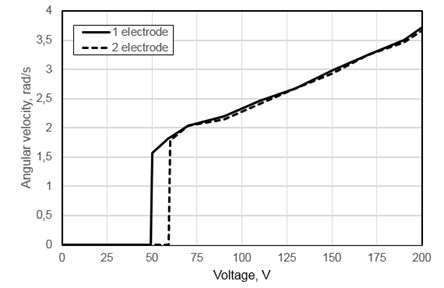
Mechanical output characteristics of the piezoelectric mirror were measured when the first excitation scheme was used. Fig. 9 shows graphs of the measured angular velocity of the reflector versus the input voltage. It can be observed that the rotation starts when applied voltage is higher than 50 Vrms or 60 Vrms for the first and second electrode, respectively. This voltage difference related with manufacturing and assembling errors of the prototype piezoelectric mirror. Angular velocity increases almost linearly with the input voltage when voltage is higher than 60 Vrms. A higher electric voltage causes larger vibration amplitude and speed of the contacting points. The piezoelectric mirror achieves maximum angular velocity of 3.7 rad/s with the input voltage of 200 Vrms.
Fig. 9Measured angular velocity versus input voltage
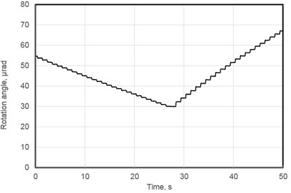
Resolution of the rotation angle in both directions was measured as well (Fig. 10). Direction of the rotations was changed by switching voltage on the electrodes. Average resolution of rotation angle equal to 10 nrad was achieved while average angular velocity was 0.915 µrad/s. By observing results of the measurements it can be noticed that angular velocities in both directions are constant in time but has different values. This can be explained because of the manufacturing and assembling errors in of the prototype piezoelectric mirror as it was mentioned before.
Fig. 10Measured forward and backward rotation angle
5. Conclusions
Novel design of piezoelectric mirror was proposed. It has simple design and can achieve nano-scale resolution of the rotation angle. Analytical and numerical analysis of the piezoelectric mirror has shown the possibilities to achieve elliptic trajectory of the contact points. Two directional rotation of the reflector can be achieved by switching voltage between different electrodes. A prototype piezoelectric mirror was developed and maximum angular velocity equal to 3.7 rad/s was achieved. Average resolution of the piezoelectric mirror is 10 nrad.
References
-
Milonni P., Eberly J. Laser Physics. Wiley, 2010.
-
Uchino K. Piezoelectric Actuators and Ultrasonic Motors. Kluwer Academic Publishers, Boston/Dordrech/London, 1997.
-
Uchino K., Giniewicz J. Micromechatronics. CRC Press, 2003.
-
Bansevicius R., Barauskas R., Kulvietis G., Ragulskis K. Vibromotors for Precision Microrobots. Hemisphere Publishing Corporation, USA, 1988.
-
Morita T. Miniature piezoelectric motors. Sensors and Actuators, Vol. 103, Issue 3, 2003, p. 291-300.
-
Tertitski L., Kuttannair K., Hunter A., Moffatt S. Laser Beam Positioning System. Patent Application No. 20110239421, 2011.
-
Zhi D., Ma Y., Si L., Wang X., Zhou P. Experimental demonstration of adaptive fiber-optics collimator based on flexible hinges. Proceedings of SPIE 9294, International Symposium on Optoelectronic Technology and Application 2014: Development and Application of High Power Lasers, 2014.
-
Lee J. Piezoelectric bimorph optical beam scanners: analysis and construction. Applied Optics, Vol. 18, Issue 4, 1979, p. 454-459.
-
Fung R., Chao S. Dynamic analysis of an optical beam deflector. Sensors and Actuators A: Physical, Vol. 84, Issues 1-2, 2000, p. 1-6.
-
Hemsel T., Wallaschek J. Survey of the present state of the art of piezoelectric linear motors. Ultrasonics, Vol. 38, 2000, p. 37-40.
-
Aimanoto T. Optical Deflector Including Narrow Piezoelectric Sensor Element Between Torsion Bar and Piezoelectric Actuator. United States Patent Application No. 20140071507, 2014.
-
Seiler R., Six M., Debarnot M., Le Letty R., Claeyssen F. The ultrasonic piezo-drive: an innovative solution for high-accuracy positioning. Proceedings of the 16th Small Satellite Conference, Logan, Utah, 2002.
-
Tzou H. S. Piezoelectric Shells. Distributed Sensing and Control of Continua. Kluwer Academic Publishers, 1993.
About this article

This work was supported by Research Council of Lithuania, Project No. MIP-045/2014.
Dalius Mazeika conducted the theoretical and numerical investigation of dynamics of the piezoelectric mirror and drafted the manuscript. Ramutis Bansevicius conceived the concept of active kinematic pairs and participated in design of the investigated piezoelectric mirror. Vytautas Jurenas and Vytautas Bakanauskas carried out the experimental investigations: impedance, angular velocity and resolution measurements of the investigated device. Genadijus Kulvietis made literature review and conducted theoretical investigation of the piezoelectric mirror. All authors read and approved the final manuscript.
