Abstract
The paper discusses the results of development and investigation of the new class of multi-degree-of-freedom robots, based on new concept. Classical rule of Robotics – the number of degree-of-freedom of robot should be equal to the number of applied actuators – is questioned here. This concept is realized by using kinematic pairs with alternating degree-of-freedom, controlled by a solitary force or moment, changing its direction in space. The number of degree-of-freedom of kinematic pair is controlled from 0 to 3, exploiting the dependence of friction forces upon oscillation in the contact zone of links.
1. Introduction
The application of smart materials in the design of classical mechanisms allow us to deal with the problems, which at a first glance seemed unsolvable. Thus, installing piezoelectric transducer into pneumatic actuator can significantly increase the resolution of it. Self-locking piston is unlocked by special form of oscillations of piezoelectric actuators, generated by connection of signal generator to segmented electrodes. Then air pressure is causing the displacement of piston, continuing till the piston is locked again. Similar idea can be used to actuate the trunk of a robot – in this case it is possible to considerably increase the number of degrees-of-freedom (DOF), enabling the grip to reach hardly accessible zones.
Very often a requirement of highly reduced number of actuators (e.g. electric motors) is important – and in this case it is possible to reduce the number of actuators up to 1 (and it is not related to total number of DOF of trunk robot). Very simplified mechanical design and low weight can also be of great importance for satellite applications. The trajectories of grip are realized by applying special software, controlling in real time the number of DOF of every kinematic pair in relation to phase of external force with alternating direction (in case when the force is generated by rotating unbalance).
2. Theoretical investigation of robots with external exciting force
Underactuation is a technical term used in robotics and control theory to describe mechanical systems that cannot be commanded to follow arbitrary trajectories in configuration space. This condition can occur for a number of reasons, the simplest of which is when the system has a lower number of actuators than degrees of freedom. In this case, the system is said to be trivially underactuated. The underactuated manipulators are ones which have more degrees of freedom than the number of actuators. They allow us to develop the simplest devices with reduced weight, cost and energy consumption. The main problem is in organizing the control of kinematic chain consisting of both passive and active links [1-4, 9].
The study of underactuated robotics focuses on building control systems which use the natural dynamics of the machines in an attempt to achieve extraordinary performance in terms of speed, efficiency, or robustness.
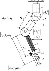
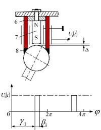
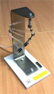
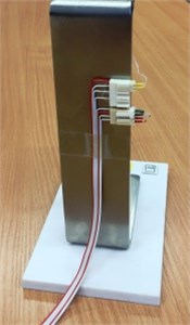
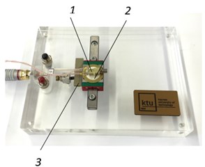
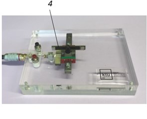
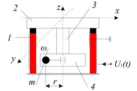
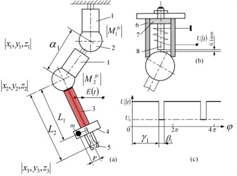
Fig. 1Schematics of robot with 4 DOF and one actuator: a) kinematic chain, b) 3-rd class kinematic pair and control of motion trajectory by selecting two levels of friction control between links (the phase γ1 of burst type excitation mode and duration β1 of it); c) and d) – front and rear view of experimental model
a)
b)
c)
d)
Fig. 1 shows the schematic of manipulator with two levels of friction control between links, implemented using piezoelectric transducers, oscillating in burst type excitation mode. Here: 1 – piezoelectric cylinder with radial poling; 2 – passive ferromagnetic sphere; 3 – sensor, sensitive to centrifugal force generated by unbalanced rotor 4; 5 – grip; 6 – cross section of piezoelectric cylinder; 7 – permanent magnet; 8 – high friction plastic, contacting piezoelectric cylinder and sphere. To ensure contacting force in the contact area of kinematic link, permanent magnet is mounted with a gap in it. To eliminate the third degree-of-freedom of every joint – angular displacement of links due to the rotation of unbalance, all structure was placed in bellow plastic hose with increased torsion stiffness.
Modelling and control of a piezo actuated robot with active centrifugal force control is performed using Uicker-Kahn method [5, 6]. The real-time dynamic model of a robot based on the Lagrange-Euler equations, that is very convenient for computer algebra implementation [5, 7]. This method enables the calculation of all the matrices of the dynamic robot model: the inertial matrix, the matrix of Coriolis and centrifugal effects and the gravity vector. The dynamic equations of an -degree-of-freedom manipulator, derived using this method, are of the following Eq. (1):
where is driving torque acting at the th joint; is generalized joint coordinate corresponding to the th degree of freedom; is transformation matrix between the th local coordinate system and the reference system; is inertia matrix of the th link with respect to local coordinate system; is mass of the link ; is the distance vector between the centre of mass of the link and the origin of reference coordinates system, expressed in the local coordinate system of the th link; is gravity vector.
The matrix may be expressed as Eq. (2):
where is a (4×4) transformation matrix between two local coordinates’ systems.
The kinematic parameters of this robot in Denavit-Hartenberg’s notation are presented in the table below [6]:
Table 1Denavit-Hartenberg’s notation i of the robot’s kinematic parameters
1 | 0 | 0 | 0 | |
2 | 90° | 0 | 0 | |
3 | 0 | 0.04 | 0 | |
4 | –90° | 0 | 0 | |
5 | –90° | 0 | 0 | |
6 | 0 | 0 | 0.04 |
The control of microrobots could be derived using mixed finite element method and computer algebra techniques. Dynamic model contains matrix equation of manipulator, that was derived using Uicker-Kahn’s method. This dynamic model is:
where is driving torque acting at the th joint; vector represents joint coordinates of manipulator; is number of degrees of freedom.
The basic dynamic equation for the piezoelectric cylinder is derived from the principle of minimum potential energy of piezoelectrical equations, and can be written as follows [10]:
where , , , , and are the matrices of mass, stiffness, electro-elasticity, capacity, and damping, respectively; , , are the vectors of structural displacement nodes, external mechanical forces, and charges coupled on the electrodes respectively, and , are the vectors of nodal potentials of the nodes associated with the electrodes. There are also mechanical and electrical boundary conditions and indices mean: 1 – are connected with signal generator, and 2 – electrodes are free electrodes. are known from signal generator.
The actuator model, based on finite element method is:
where is nonlinear highly varying in time driving force and is control input, is displacement vector of nodal point in cylindrical coordinates. As shown in [10], taken into account piezoelectric Eq. (4) and electrical boundary conditions, the stiffness matrix in Eq. (5) is:
For real-time dynamics above mentioned equation can be simplified using eigenvectors of system. Complete control scheme can be built using criteria:
where:
and is resonant frequency and is a number of periods.
The external torque vector placed in the gripper and rotating in the plane perpendicular to the gripper direction is expressed in the form:
where is the mass of unbalance; is radius; is angular velocity.
The expressions of generalized torques corresponding to the coordinates are calculated recursively, starting from the gripper. For this purpose the transformation matrix could be represented by submatrices:
The recursive algorithm consists of two steps for every local coordinate. Therefore, first step is calculation of active forces and second is definition of the active torques. This algorithm may be expressed in the form [8]:
where , see Eq. (3). Expressions are calculated starting from to .
The generalized torque for th joint may be obtained in the form:
where is the unit vector of corresponding axis, , where are unit functions:
and final expressions for switching moments are:
where is parameter that depends of required motion’s precision.
3. The systems with one DOF
Manipulators with two levels of friction control between links, implemented using piezoelectric transducers, oscillating in burst type excitation mode, can be effectively used for simple one DOF mechanisms, performing translational motion. In the first modification unbalanced rotor is used (Fig. 2(a)); the phase of its rotation is measured by special sensor in a form of piezoelectric disk and multilayer piezoelectric plate is in a contact with moving table, stopping it when burst type oscillation mode is switched-off. In the second modification (Fig. 2(b)) rotating unbalance is replaced by piezoelectric bimorph, and as in first case, multilayer piezoelectric plate is in contact with table.
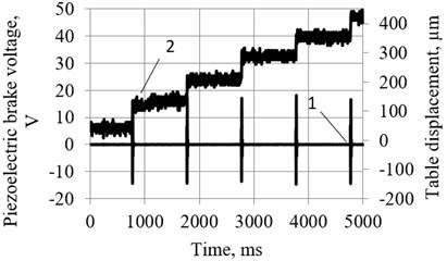
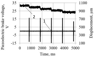
The resolution of the motion of the manipulator with piezoelectric bimorph as a source of exciting force and piezoelectric brake-force transducer, oscillating in burst type excitation mode (Fig. 2(b)) is of the order of 10…100 µm (Fig. 3).
Fig. 2Two modifications of manipulators with two levels of friction control between links, implemented using piezoelectric transducers, oscillating in burst type excitation mode: a) with unbalanced rotor as a source of exciting force; b) with piezoelectric bimorph, performing relatively low frequency bending oscillations (1 – miniature electrical motor with unbalance rotor, 2 – sensor in a form of piezoelectric plate, 3 – piezoelectric brake, oscillating in burst type mode, 4 – piezoelectric bimorph)
a)
b)
Fig. 3Resolution of motion of the manipulator with piezoelectric bimorph as a source of exciting force and piezoelectric brake-force transducer, oscillating in burst type excitation mode (Fig. 1(b)): 1 – signal of piezoelectric brake-force transducer; 2 – motion of the manipulator. a) In forward direction resolution – 60…80 µm; b) in backward direction resolution – 40…60 µm
4. The systems with two DOF
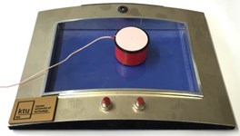
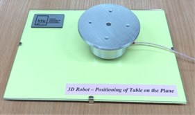
Two modifications of miniature tables were designed, using centrifugal force of unbalanced rotor as a driving force, while the control of displacement was effected using two levels of friction control between links, implemented using piezoelectric transducers, oscillating in burst type excitation mode (Fig. 4).
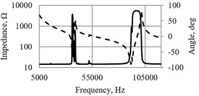
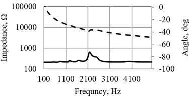
The impedance of piezoelectric cylinder is given in Fig. 5(a), the impedance of sensor (with sectioned electrode) – in Fig. 5(b). The experimental investigations were carried out by impedance analyser WAYNE KERR 6500B; resonant frequency of piezoelectric cylinder was 96,362 kHz, resonant frequency of sensor – 2,176 kHz.
The main advantages of the positioning systems, shown in Fig. 4, are: (a) simple design and low cost; (b) relatively low cost of control unit; (c) – resolution is of the order of 10...30 µm and depends mainly of the mass of the table. This type of the systems can be used in low cost domestic appliances, teaching aids and toys.
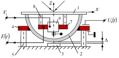
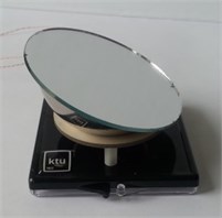
More complicated applications are shown in Fig. 6 They include the artificial joint (Fig. 6(a)), consisting of dynamically unbalanced rotor and piezoelectric actuator, stopping the motion of the joint when burst type excitation mode is periodically switched-off. Similar schematic – 2 DOF laser deflector – is shown in Fig. 6(b), 6(c), and is based on rotating static unbalance and piezoelectric transducer in a form of disk, controlling the motion of a mirror.
Fig. 4Two modifications of miniature tables with friction control between piezoelectric cylinder and frame: 1 – piezoelectric cylinder, 2 – table, 3 – sensor, 4 – electric motor with unbalanced rotor
a)
b)
c)
Fig. 5a) Impedance of piezoelectric cylinder and b) buzzer, used as a sensor (Fig. 3(a), 3(b))
a)
b)
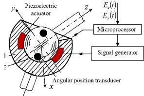
Fig. 6a) Robot joint with dynamically unbalanced rotor and system to control the friction between two kinematic links and b) similar application for deflection of laser beam in two directions: 1 – mirror, 2 – ferromagnetic half-sphere, 3 – permanent magnet, 4 – piezoelectric disk with poling vector, coinciding with axis z, 5 – support, 6 – miniature electric motor with unbalanced rotor, 7 – sensor, 8 – sensor holder; c) view of experimental deflector
a)
b)
c)
In Fig. 4 and 6 a special link with increased torsion stiffness is used to eliminate the third degree-of-freedom of joint, due to the rotation of unbalance (not shown here).
Manipulators with two levels of friction control between links, implemented using piezoelectric transducers, are controlled by special device, regulating burst type oscillations phase and its duration (Fig. 7). Signals from sensor 3 (Fig. 1(a)) are transformed into meander type triggering signals (5 V); the front of them defines the delay moment of harmonic signal (, Fig. 1(b)) and second multivibrator defines the width of the burst type excitation (, Fig. 1(b)). Thus the spatial angle and the maximum angle of displacement (caused by one cycle of burst excitation) are implemented.
Similar schematic of robot with ferromagnetic cylinder in contact with passive sphere, and friction forces controlled by magnetic field, is shown in Fig. 8. Here 1 – ferromagnetic cylinder, 2 – passive ferromagnetic sphere, 3 – sensor sensitive to centrifugal force , generated by unbalanced rotor 4, 5 – grip, 6, 7, 8 – magnetic chain, controlled by .
Fig. 7One channel device for controlling the phase of burst type excitation and its duration
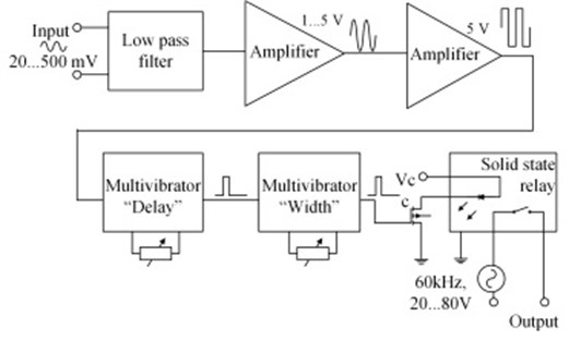
Fig. 8A case with friction control by electromagnetic forces
5. Conclusions
Manipulators with two levels of friction control between links, implemented using piezoelectric transducers, oscillating in burst type excitation mode, are proposed and investigated. The examples of simple mechanisms of this type are given; more complicated cases with robots, having unlimited DOF, are suggested. Theoretical investigations of robots with one external exciting force are carried on, which can be used to create a software to control the robot, reaching the required motion’s precision.
References
-
Bansevicius R., Sarkauskas K. K., Tolocka R. T. Underactuated manipulator with control based on variable dynamic properties of joints. Electronics and Electrical Engineering, Vol. 79, Issue 7, 2007.
-
Deimel Raphael, Brock Oliver A novel type of compliant and underactuated robotic hand for dexterous grasping. The International Journal of Robotics Research, 2016.
-
De Luca A., Iannitti S., Mattone R., Oriolo G. Advanced intelligent mechatronics. Proceedings of IEEE/ASME International Conference, Vol. 2, 2001, p. 861-855.
-
Jain Abhinandan, Rodriguez Guillermo An analysis of the kinematics and dynamics of under actuated manipulators. IEEE Transactions on Robotics and Automation, Vol. 9, 1993, p. 411-422.
-
Bansevicius R., Cepulkauskas, Kulvietiene R., Kulvietis G. Computer Algebra for Real-Time Dynamics of Robots with Large Number of Joints. Lecture Notes in Computer Science, Vol. 3039, Springer-Verlag, Berlin, Heidelberg, New York, 2004, p. 278-285.
-
Vucobratovic K. M., Kircanski M. N. Real-time Dynamics of Manipulation Robots. Springer-Verlag, Berlin, Heidelberg, New York, 1985.
-
Kulvietiene R., Kulvietis G., Tumasoniene I. A symbolic-numeric vibration analysis of systems with many degrees of freedom. Journal of Mechanical Engineering, Vol. 52, Issue 5, 2006, p. 309-316.
-
Bansevicius R., Kulvietis G., Rovetta A. Flexible robots with one exciting force. Proceedings of 27th International Symposium on Industrial Robots, 1998, p. 975-980.
-
Tso S. K., Yang T. W., Xu W. L., Sun Z. Q. Vibration control for a flexible link robot arm with deflection feedback. International Journal of Nonlinear Mechanics, Vol. 38, 2003, p. 51-62.
-
Ragulskis K., Bansevicius R., Barauskas R., Kulvietis G. Vibromotors for Precision Microrobots. Hemisphere Publishing Corp, USA, 1988.
About this article

The work was supported by the Research Council of Lithuania under the Project SmartTrunk, No. MIP-084/2015.
