Abstract
The narrowband adaptive algorithm has been used in vibration control for its advantage. The narrowband filter in algorithm is important in the implementation for application. This paper suggests a new narrowband filters architecture in adaptive algorithm. We design a cross-band filter bank which can deal with the line spectrum located in the edge of narrow band. The new architecture is tested and show that it improves both the convergence speed and the algorithm’s steady.
1. Introduction
The narrowband adaptive algorithm is a control algorithm for the line spectrum vibration of mechanical vibration. The narrowband adaptive algorithm published recently can achieve good results for stable multi line spectrum vibration (or noise) control. The reference signal of [1-3] algorithm and the error signal are not broadband signal but the signal line. Extraction of the narrowband signal is often obtained by pre-filter, narrowband filter ideal should be satisfied in the pass band signal without distortion, stopband is weaken and the steep transition zone, meet the filter of such nature (such as elliptic filter) often sacrifice some other properties, such as phase transition zone in mutation serious nonlinear enhancement. Newton algorithm [4, 5] is a fast-convergent algorithm. Even if the secondary channel matrix eigenvalue dispersion is large, it can also ensure stability and achieve faster convergence speed than traditional FxLMS algorithm.
From the above, we can see that the current narrowband control algorithm is mainly aimed at frequency stability, and it is also studied under the assumption that the narrowband filter can extract line spectrum signal completely.
In this paper, the influence of the pre-narrow-band filter characteristics on the Fx-Newton algorithm is analyzed. Based on this, a cross-band narrow-band filter bank is proposed. The influence of the filter characteristics on the convergence of the algorithm is analyzed. In the experimental part, the results show that the algorithm can converge quickly to achieve excellent control effect.
2. The Fx-Newton narrowband algorithm and analysis of narrowband filter
2.1. The derivation of Fx-Newton narrowband control algorithm
It is assumed that the system is a linear system, and the frequency components of the system are orthogonal to each other, so the single frequency case can be analyzed only.
The frequency domain update formula of Fx-Newton algorithm [1, 6] is:
The secondary channel that corresponds to the route control signal to the error signal.
In practical applications, the vibration signals are usually superimposed by multiple frequency components, and the frequency domain algorithm can be independently controlled by the orthogonal characteristics of each frequency component. At present, there are many ways to extract line spectrum signals in time domain. In this paper, a narrow band pass filter is used to extract single frequency line spectrum signal. The advantage is that it doesn't need to estimate frequency, and it can ensure that the filtered line spectrum signal is consistent with the original signal frequency.
The frequency response of the narrowband filter is at . The frequency spectrum at of reference signal, disturbance signal and error signal before filtering is , and respectively, and the correlation between them is:
The performance function of the control algorithm is:
Then the complex gradient vector of the function relative to the controller , and their first derivative relative to is:
So, the narrow-band Fx-Newton algorithm in frequency domain iterative formula can be obtained:
In which:
We can get the optimal controller:
We can see that when the line spectrum to be controlled is at the edge of two band-pass filters, the influence of transition band cannot be neglected. The following analysis of the filter characteristics of the convergence process and the impact of the results.
2.2. Influence of narrowband bandpass filter on algorithm
By comparing Eqs. (1), (8) and (11), we can see that for the same adaptive system, the addition of the pre-filter does not cause the algorithm principle error, but it will change the convergence process of algorithm and the optimal controller coefficients. Suppose the frequency response of the narrow-band filter is . Taking a fourth-order elliptic band-pass filter for an example, when the line spectrum is at the edge of the band, the amplitude response of the filter is less than the amplitude response within the pass band and the phase will change drastically. Usually in the sub-band narrowband control algorithm, often use the filter group shown in Fig. 1 for signal extraction, if the filter pass-band spacing is too large (Fig. 1(a)), can effectively prevent the signal Aliasing, but there is a possibility that the signal will be missed or that the signal has been severely attenuated, resulting in no control effect or poor control effect. If the filter pass-band is immediately followed (Fig. 1(b)), the signal fluctuations will lead to the algorithm to judge the signal frequency band repeatedly, nor is it the result we expected; or both compromise (Fig. 1(c)), but this cannot solve the problem fundamentally.
Fig. 1Three narrowband filter bank structures
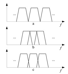
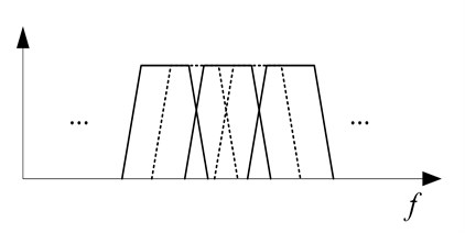
Fig. 2The improved filter bank in narrowband algorithm
More seriously, when the algorithm is at the edge of the band, it is often judged as the change of the frequency of the reference signal to trigger the restart of the algorithm, which is not conducive to the stability of the algorithm. In fact, the signal fluctuates within a small interval Will affect the secondary channel characteristics of the algorithm, without the need to make major adjustments to the algorithm.
First, let us analyze the impact of narrowband filters on the optimal controller. Substitute into Eq. (10), we can get:
It can be seen that the change of the filter characteristics will lead to the change of the optimal controller parameters. The magnitude of the filter influences the size of the optimal controller coefficients. The phase affects the distribution of the controller coefficients. In order to lose the generality, suppose the phase of the filter is constant, namely let , is the amplitude factor. Into the Eq. (8), if the algorithm is from we can obtain:
Eq. (13) shows that the optimal controller coefficient increases, especially when the reference signal frequency is at the edge of the band. In the convergent process Eq. (12), the first and second terms are the renewal formulas of the weight coefficients when the filter is . Since we assume that the phases are invariant, the convergence direction of the weight coefficients should be the same in both cases. Therefore, the second term indicates the direction of convergence. It can be seen that the directions of the third term and the second term are the same, that is, the recursion convergence increases with the same step factor, but the increased ratio is better than the optimal control the multiplication factor of increasing the coefficient is small, so will reduce the speed of system convergence.
3. Improvement and realization of the algorithm in time domain
From Section 1.2, we can see that the improvement on the filter not only ensures the quality of the signal, but also minimizes the aliasing and ensures that the algorithm does not change the narrow-band analysis filter frequently during the execution. To this end, this paper designed a cross-band filter bank, shown in Fig. 2.
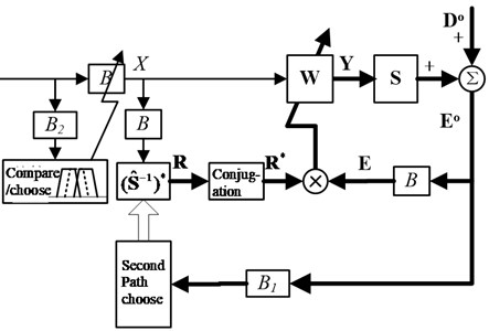
The improved pre-filter bank adds a cross-band band-pass filter on the basis of Fig. 1(c), so that the pass bands of adjacent filters in the filter bank overlap to some extent, effectively avoiding that when the signal is at However, it should be noted that the secondary channel selection phase of the signal processing is still performed by the pre-improvement band division as shown in Fig. 1(c), which can reduce the complexity of secondary channel modeling degree, to avoid increasing the amount of computation of the original algorithm. The frequency domain block diagram of the improved algorithm is shown in Fig. 3. After the error signal in the picture is filtered by the filter bank, the frequency band with the largest energy is selected according to the energy of each frequency band signal for the algorithm to call the secondary channel data, The filtered reference signal of bank selects the optimal narrow-band filter in the same way (in this case, the possible signal will be in two adjacent frequency bands in filter bank , but will not change the energy of each frequency band So it has little effect on the algorithm), filter the reference signal into the algorithm to eliminate the adaptive controller update operation, the other with the same algorithm. The accurate frequency estimation also can better select the narrow band filter, but it needs extra computation, and the synthesized single frequency reference signal cannot keep the original signal characteristics to the maximum. The improved algorithm can effectively solve the problem of slow convergence of the transition band caused by the design of narrowband filter banks in the narrowband adaptive algorithm and the instability of the algorithm.
Fig. 3The improved Fx-Newton algorithm structure
To improve the real-time performance of the algorithm, the execution of the algorithm is completed in the time domain.
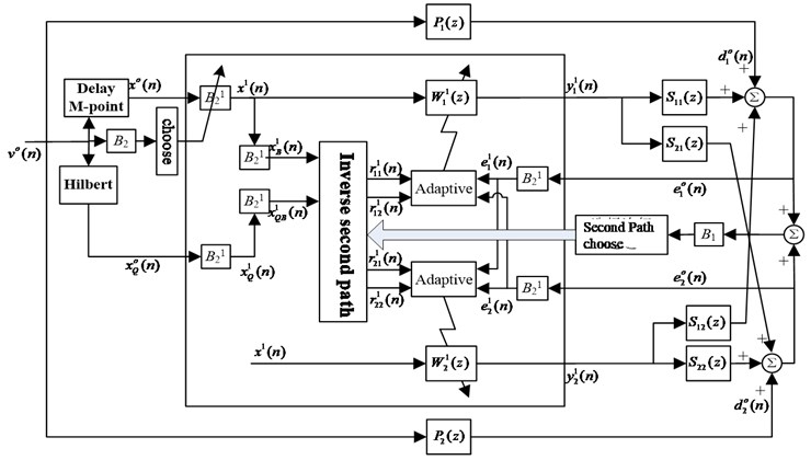
Fig. 4 is a block diagram of a multi-channel narrow-band Fx-Newton time-domain algorithm (taking a system with a single line spectrum and with two actuators and two sensors as an example). The algorithm divides the whole frequency band into a certain number of narrowband frequency bands, extracts the target line spectrum by narrowband filter bank , and multiple control subsystems can work in parallel to control multiple line spectra. In each frequency band of , the secondary channel identification results at its center frequency are taken as the secondary channel model, without adding the identification complexity and computational complexity of the original algorithm. The secondary channel inverse model filter uses the second-order time-frequency filtering model in [6].
The second-order section uses a direct type II structure to achieve.
Fig. 4The improved multi-channel narrowband Fx-Newton structure in time domain
4. Experimental study on active control
4.1. Experimental setup
The experiment is carried out on the main and passive hybrid vibration isolation test platform for diesel generator set. The acceleration signals near the 6 hybrid vibration isolators on the base are taken as the error signals. The objective function is the sum of squares of the error signals.
4.2. Comparison of Fx-Newton algorithm and filter modified Fx-Newton algorithm
The frequency of the reference signal is adjusted to 62 Hz, and the signal frequency at this time is at the edge of the band in the B1 filter bank. Two algorithms are run in the same convergence step to compare the convergence.
Fig. 5The compare of convergence rate when using shaker excites at 62 Hz
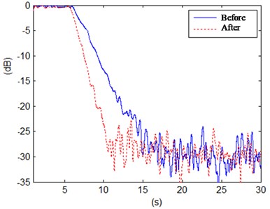
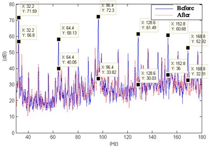
Fig. 6Power spectrum density of the acceleration signals before and after control
As can be seen from the Fig. 5, when at the edge of the band, the improved algorithm has a faster convergence rate than the original algorithm under the condition of guaranteed stability, and can only converge completely in only 4 seconds.
4.3. Multiline spectrum control in diesel generators
The diesel generating set is operated to excite the vibration components superimposed by the broad spectrum and the multitude of spectrums. The acceleration of the upper deck is taken as a reference signal, and the Fx-Newton algorithm is used for active control at multiple speeds.
Fig. 6 shows the diesel engine power at different speeds and other conditions under control before and after the base error of the power point density measurement points. Under each operating condition, the active control system automatically selects the most prominent 10 to 11 line spectra in the frequency band of 30 to 180 Hz for control, and still has a good convergence effect when the line spectrum is at the edge of the frequency band.
5. Conclusions
In this paper, a new narrow-band filter bank is formed by adding a set of cross-band narrow-band filters. The improvement makes the algorithm converge quickly and effectively in a wide range of frequency, which expands the application of Fx-Newton algorithm in active vibration control. The experimental results show that the improved line spectrum vibration algorithm at the edge of the frequency band has a faster convergence rate than the former one.
References
-
Liang Q., Duan X. S. Control of electromagnetic suspension vibration isolator based on filter x-LMS algorithm. Journal of Vibration and Shock, Vol. 29, Issue 7, 2010, p. 201-203+246.
-
Zhang Z. Y., Wang J. F., Zhou J. P., Huan H. X. Adaptive vibration control with tracking filters. Journal of Vibration and Shock, Vol. 2, 2009, p. 64-67+201.
-
Yang Z. H., Liu Q. H. An active noise control algorithm without secondary path identification. Technical Acoustics, Vol. 29, Issue 4, 2009, p. 428-432.
-
An F. Y., Sun H. L., Li X. D., Tian J. Optimization of parameters in decentralized adaptive active control algorithm. Journal of Vibration Engineering, Vol. 26, Issue 1, 2013, p. 48-54.
-
Fuller C. R., Elliott S. J., Nelson P. A. Active Control of Vibration. Academic Press, San Diego, 1986.
-
Li Y., He L., Shuai C. G. Mimo Fx-Newton narrowband algorithm and experiment of active vibration isolation on diesel generator. Acta Acustica, Vol. 40, Issue 3, 2015, p. 391-403.
About this article

