Abstract
Investigation of time averaged reflection moiré measurements of vibrations of a wing is performed in this paper. Interpretation of reflection moiré images on a shallow surface of a wing is more complicated than on a plane surface. For this purpose, a special simplified two-dimensional numerical model is developed and the possibilities of application of this method of measurement of vibrations are investigated.
1. Introduction
Vibrations of wing type structures take place in the process of operation of planes. Their investigation is an important engineering problem. Time averaged reflection moiré measurements of vibrations can be performed for various elastic structures. Here this method is applied for measurement of vibrations of wing type structures. Wing has a shallow surface. Interpretation of reflection moiré images for such surfaces is more complicated than for conventional plane surfaces. A special simplified two-dimensional numerical model is developed for the investigation of this problem. It is shown that this method can be applied for measurement of vibrations of wing type structures.
In the previous paper [1] projection moiré measurements of vibrations of a wing were performed, the experimental setup was presented in detail and typical experimental results were described. This paper continues the investigations presented there and is devoted to the investigation of possibilities of application of time averaged reflection moiré techniques to the same problem.
Analysis of time averaged moiré techniques was earlier presented in [2]. Measurement of dynamics of a plate by moiré methods is described in [3]. Diffraction moiré for investigation of dynamics is presented in [4]. Moiré interferometry for analysis of dynamics is described in [5]. Review of basic experimental methods for investigation of elastic structures is presented in [6]. Computer generation of experimental images is described in [7]. Time averaging for holographic applications is presented in [8]. Review of moiré interferometry in experimental mechanics is performed in [9]. Experimental high rate deformation and shock studies are investigated in [10]. Specific applications of geometric moiré are presented in [11]. Time averaged moiré is applied for analysis of vibrations in [12]. Thus, moiré methods are among the basic engineering methods for analysis of dynamics of elastic structures.
2. Description of the method of reflection moiré for wing type structures
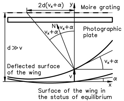
Further and denote the axes of the system of coordinates. It is assumed that the surface of the wing is shallow and does not deviate much from the axis. Moire grating and the photographic plate are assumed to be one over another approximately at the same value of the coordinate. The schematic diagram of experimental investigation is illustrated in Fig. 1.
In Fig. 1, denotes the displacement of the wing in the direction of the axis, denotes the derivative of with respect to , denotes the angle of the surface of the wing in the status of equilibrium with the axis, denotes the distance between the axis and the moire grating with photographic plate, denotes the normal vector to the deflected surface of the wing.
Fig. 1Schematic diagram of experimental investigation
3. Simplified 2D model for the analysis of time averaged reflection moiré for vibrations of a wing type structure
Plane strain problem is investigated; in this paper and denote the axes of coordinates; and denote displacements in the directions of those axes of coordinates.
The stiffness matrix has the usual form:
where:
where , , …, are the shape functions of the two-dimensional Lagrange quadratic finite element, , here denotes modulus of elasticity and ν denotes Poisson’s ratio.
The mass matrix has the usual form:
where is the density of material of the structure and:
The eigenmodes are calculated and further the investigated eigenmode is denoted as
In order to determine the nodal values of the derivative the procedure of conjugate approximation is applied. Thus, the system of linear algebraic equations is solved:
where:
where:
also, where:
where , ,…, are values of the derivative at the nodes of the finite element mesh, is the total number of nodes of the mesh, also where:
where:
where:
Intensity of the reflection moiré image is calculated on the upper surface of the structure for the following values of local coordinates of the finite element
where
Global coordinates are calculated as:
where , ,…, are nodal coordinates of the finite element.
Angle of the tangential direction with the axis is denoted as and is determined from:
where:
where are nodal values of this angle for the analyzed finite element. In the investigation the surface of the wing is assumed to be shallow and thus those angles are considered to be small.
The derivative is now calculated as:
Moiré grating and the photographic plate are approximately parallel to the shallow surface of the structure and the distance between them and the shallow surface of the structure is assumed approximately constant and equal to . Intensity of the time averaged reflection moiré image is calculated as:
where is a large integer number and determines the width of moiré lines.
Intensity is graphically represented in the normal direction to the upper surface of the structure, thus the coordinates of the point representing the intensity are:
4. Results of analysis of time averaged reflection moiré measurement of vibrations of a wing type structure
The investigated structure consists of one row of elements located on one fourth of a circle, of a straight part with the length equal to the length of the middle line of half of a circle and of another one fourth of a circle. All displacements of the three nodes on the left end and of the three nodes on the right end are assumed equal to zero. The following parameters of the structure are assumed: modulus of elasticity 6×10⁸ Pa; Poisson’s ratio 0.3; the density of the material 785 kg/m3.
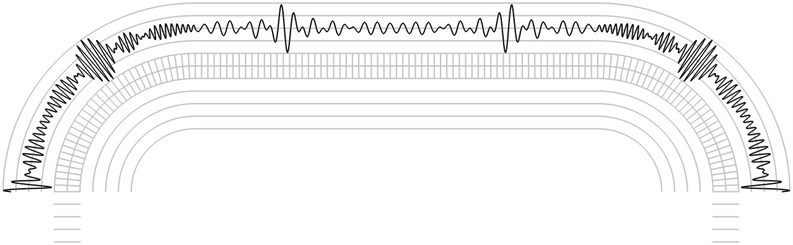
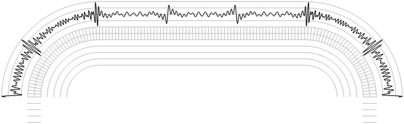
The finite element mesh and lines equidistant in the normal direction to the surfaces of the structure are shown in grey colour. Intensity of the time averaged reflection moiré image on the upper surface is represented in black colour.
The first eigenmode is shown in Fig. 2, the second eigenmode is shown in Fig. 3, …, the fifth eigenmode is shown in Fig. 6.
Fig. 2The first eigenmode
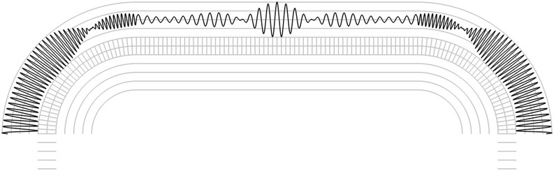
Fig. 3The second eigenmode
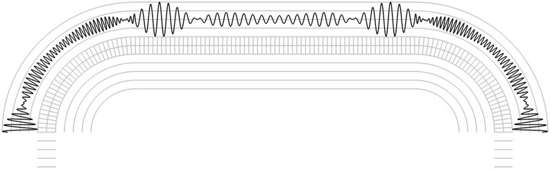
Fig. 4The third eigenmode
Graphical relationships are applicable in hybrid experimental – numerical procedures for interpretation of time averaged reflection moiré images on the investigated shallow surfaces of wing type. For such surfaces having slow variation of curvature graphical representations of the described type are to be investigated for a number of cross sections of the analysed wing type structure.
The investigation of reflection moiré images is performed by calculating the number of maximums of the envelope of the intensity function. From Fig. 2 it is seen that the envelope of the intensity function has 7 internal maximums. From Fig. 3 it is seen that the envelope of the intensity function has 8 internal maximums. From Fig. 4 it is seen that the envelope of the intensity function has 13 internal maximums. From Fig. 5 it is seen that the envelope of the intensity function has 15 internal maximums. From Fig. 6 it is seen that the envelope of the intensity function has 17 internal maximums. This corresponds to the fact that higher eigenmodes have more complicated patterns of displacements of the elastic structure and this usually results in more complicated reflection moiré images. Thus, from the reflection moiré image it is possible to identify the number of excited eigenmode.
Fig. 5The fourth eigenmode
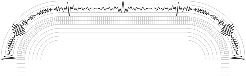
Fig. 6The fifth eigenmode
5. Conclusions
Wing type structures experience vibrations. Study of those vibrations is important for safety of flight. Time averaged reflection moiré is a typical measurement technique applicable for wing type structures. Interpretation of reflection moiré images on a shallow surface of a wing is investigated in this paper. This interpretation is more complicated than conventional applications of the same techniques for a plane surface. A special simplified two-dimensional numerical model is developed. Application of this method of measurement of vibrations is investigated. This paper continues the investigations presented in the previous paper and is devoted to the investigation of possibilities of application of time averaged reflection moiré techniques to the same problem.
Graphical relationships are applicable in hybrid experimental – numerical procedures for interpretation of time averaged reflection moiré images on the investigated shallow surfaces of wing type. For such surfaces having slow variation of curvature graphical representations of the described type are to be investigated for a number of cross sections of the analysed wing type structure. The investigation of reflection moiré images is performed by calculating the number of maximums of the envelope of the intensity function. From the reflection moiré image it is possible to identify the number of excited eigenmode.
References
-
Maskeliūnas V., Maskeliūnas R., Paškevičius P., Ragulskis L. Measurement of vibrations of a wing. Journal of Measurements in Engineering, Vol. 4, Issue 3, 2016, p. 183-187.
-
Ragulskis K., Maskeliūnas R., Zubavičius L. Analysis of structural vibrations using time averaged shadow moiré. Journal of Vibroengineering, Vol. 8, Issue 3, 2006, p. 26-29.
-
Huimin X., Guotao W., Fulong D., Guangjun Z., Xingfu L., Fangju Z., Aiming X. The dynamic deformation measurement of the high speed heated LY12 aluminium plate with moiré interferometry. Journal of Materials Processing Technology, Vol. 83, Issues 1-3, 1998, p. 159-163.
-
Deason V. A., Epstein J. S., Abdallah A. Dynamic diffraction moiré: theory and applications. Optics and Lasers in Engineering, Vol. 12, Issues 2-3, 1990, p. 173-187.
-
Kokaly M. T., Lee J., Kobayashi A. S. Moiré interferometry for dynamic fracture study. Optics and Lasers in Engineering, Vol. 40, Issue 4, 2003, p. 231-247.
-
Timoshenko S. P., Goodier J. N. Theory of Elasticity. Nauka, Moscow, 1975, (in Russian).
-
Soifer V. A. Computer processing of images. Herald of the Russian Academy of Sciences, Vol. 71, Issue 2, 2001, p. 119-129, (in Russian).
-
Vest C. Holographic Interferometry. Mir, Moscow, 1982, (in Russian).
-
Han B., Post D., Ifju P. Moiré interferometry for engineering mechanics: current practices and future developments. Journal of Strain Analysis for Engineering Design, Vol. 36, Issue 1, 2001, p. 101-117.
-
Field J. E., Walley S. M., Proud W. G., Goldrein H. T., Siviour C. R. Review of experimental techniques for high rate deformation and shock studies. International Journal of Impact Engineering, Vol. 30, Issue 7, 2004, p. 725-775.
-
Dai F. L., Wang Z. Y. Geometric micron moiré. Optics and Lasers in Engineering, Vol. 31, Issue 3, 1999, p. 191-198.
-
Liang C. Y., Hung Y. Y., Durelli A. J., Hovanesian J. D. Time-averaged moiré method for in-plane vibration analysis. Journal of Sound and Vibration, Vol. 62, Issue 2, 1979, p. 267-275.
About this article

