Abstract
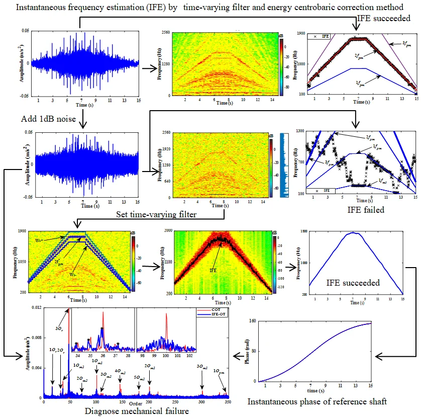
Under the premise that the instantaneous speed can be accurately measured or precise estimated, order tracking is considered to be a classical and effective technique for non-stationary vibration analysis of rotating machinery. The meshing frequency components of the vibration signal measured from complex gearbox system interfere with each other mutually. The energy centrobaric correction method exhibits exact instantaneous frequency estimation (IFE) ability under the interference, but is susceptible to strong noise. Combining with time-varying filter and energy centrobaric correction method, a tacholess order tracking technique for gear fault diagnosis under the rotating frequency multi-linear fluctuation is proposed. The time-varying filter is designed to filter the strong noise signal, and then IFE could be accurately calculated from the filtered signal by energy centrobaric correction method. The instantaneous phase of reference shaft based on the Vold-Kalman filter (VKF) is used for angular resampling of the original vibration signal. The results show that the shaft rotating speed could be accurately identified from extracted gear meshing components. The order spectrum obtained by the proposed method with tacholess is substantially the same as the order spectrum obtained by a tachometer. Simulation analysis and experimental results verify the advantages of proposed tacholess order tracking technology for monitoring and fault diagnosis of gearbox vibration under the condition of strong noise and large speed variation.
Highlights
- The energy centrobaric correction method exhibits exact instantaneous frequency estimation (IFE) ability under the interference, but is susceptible to strong noise.
- Combining with time-varying filter and energy centrobaric correction method, a tacholess order tracking technique for gear fault diagnosis under the rotating frequency fluctuation is proposed.
- The obtained order spectrum by the method is in agreement with the order spectrum by computed order tracking (COT) to a considerable extent.
- The proposed method can be further combined with other signal processing technique, to extract the feature of fault of mechanical systems under multi-linear fluctuation without tachometer.
1. Introduction
Working under speed fluctuation, rotating machines are usually easier to reflect the inherent characteristics and fault characteristics of the system [1]. When the broken tooth fault of the gear meshes with other gear, the response exhibits impact characteristics [2]. The driving speed curve of the traditional mine hoist mainly adopts the trapezoidal line diagram [3], the motor speed will fluctuate multiple linear, and the gearbox system will undergo linear acceleration, uniform speed and linear deceleration. Converting the time domain non-stationary vibration into frequency domain signals directly will result in spectral blurring [4]. Order tracking is a method of great value for vibration signal analysis because of its effectiveness in identifying and separating speed-related vibration [5]. Tacholess order tracking technology has gotten widespread concern, for avoiding installation of tachometers or angle encoders by estimating instantaneous frequency of shaft [4, 6] or instantaneous phase of shaft [7, 8]. The angular-stationary signal acquired from non-stationary signal by equal angle resampling can represent fault features more intuitively [9].
The Chebyshev type II filter is called type Inverse Chebyshev filter, the magnitude response has a maximally flat passband and equiripple stopband [10, 11]. The vibration signal is divided into consecutive non-coincident multi-segment signals, each of which can be approximated as a quasi-stationary signal. As part of the time-varying filter, a different Chebyshev II filter is provided for each segmented signal component.
The instantaneous frequency (IF) of the filtered signal filtered by the time varying filter can be estimated based on vibration analysis. The energy centrobaric correction method is widely used in IFE, as a kind of discrete spectrum correction technology, its related theory was proposed by Ding Kang et al [12]. According to the torsional vibration of an engine, the rotational speed of the crankshaft can be determined by the energy centrobaric correction method [13]. The instantaneous rotational frequency of eccentric DC shaft is estimated based on the energy centrobaric correction method [14]. Lin Hinbin et al. [15] improved the energy centrobaric correction method to estimate the speed of a reciprocating engine, which worked in a steady-state or small speed fluctuation condition. He GuoLin et al. [9, 16] improved energy centrobaric correction method to identify rotational speed of planetary gear shaft in wind turbine under wide speed variation conditions.
After rotation frequency of the shaft or the meshing frequency of gear known, the key of order tracking is equal angle resampling of vibration signal, according to the instantaneous phase of the reference shaft. Zhao Ming et al. [17] proposed a Chirplet-based estimation of instantaneous meshing frequency approach and then phase of shaft was obtained by gear meshing component extracted based on VKF. In Ref. [7], acquired by generalized demodulation and Hilbert transform, instantaneous phase of an adaptively filtered fault bearing signal can provide reference for equal angle resampling of filtered envelopes, which filtered based on Fast-kurtogram. The instantaneous frequency of filtered bearing signal obtained by the short-time Fourier transform (STFT), which filtered by the fast-spectrum kurtosis, then the angular domain signal and the order spectrum were obtained by a new resampling algorithm [18]. S. Schmidt et al. [19] improved the maximum value tracking algorithm and combined VKF to extract the instantaneous phase information of the vibration signal. The instantaneous phase of the shaft can be obtained by integrating the instantaneous frequency, which is identified by dynamic path optimization [20]. In the absence of a tachometer, the instantaneous frequency of sun gear can be extracted from complex vibration signal of planetary gearbox by local mean decomposition (LMD) and synchro squeezing transform (SST), with sun gear has a broken tooth [21]. However, considering that the fixed shaft gearbox is at low-speed stage, the gears may be the first to fail due to excessive torque. When it is difficult to extract the instantaneous frequency of the sun gear from the strong noise signal directly, how to diagnose low speed gear failures under tacholess is worth exploring.
At present, there are few researches on fault diagnosis of low-speed gears transmission system for strong noise under variable speed. In order to execute tacholess order tracking on high noise signal, time-varying filter and energy centrobaric correction method are used for filtering and estimating instantaneous frequency, respectively. Angular-stationary signal is obtained by equal angle resampling under the phase of reference shaft known.
The rest of this paper is organized as follows. The relevant theory is briefly reviewed in Section 2. The procedures of the proposed method are described in Section 3. The feasibility of the proposed method is validated by simulations in Section 4 and experiments in Section 5. Finally, conclusions are given in Section 6.
2. Theory introduction
2.1. IFE based on energy centrobaric correction method
The IF of a single harmonic signal can be estimated from the first-moment of the time-frequency distribution (TFD) [22]. But for realistic engineering signals, which contain multiple frequency components, the IF of single harmonic component cannot be estimated directly from TFD [13]. The individual component’s first-moment of STFT equals to IF approximately [9, 13, 14], which can be extracted by peak search commonly. The first-moment of TFD can be expressed as [23]:
where and relate to power TFD and STFT of signal respectively.
By some symmetric spectral window functions, the energy centers are located in or close to origin of the coordinate system [9, 13, 14]. The side lobes of the Hanning symmetric window function decay rapidly [9], providing high correction accuracy in spectrum analysis.
The corrected frequency and amplitude of energy centrobaric correction method could be defined as:
where and correspond to the line number of the maximum power amplitude and frequency resolution, respectively. relates to value of the th power spectral line. is energy recovery coefficient of the window function used in the analysis.
Energy centrobaric correction method can be used for instantaneous frequency estimation, since Eq. (2) is discrete expression of Eq. (1) essentially.
The procedures of IFE based on the energy centrobaric correction method are described below:
Step 1: Assuming the length of the vibration signal is , the overlap rate . Choose a kind of window function for correction, the points for window shifting are . The length of each segment signal to be analyzed is . The vibration signal is divided into “” segment signals, where denotes rounding of . For the th segment signal (), the relative position in is . The time corresponding to the midpoint of the segment signal is (.
Step 2: According to the 1th segment signal to calculate its power spectrum via fast Fourier transform (FFT). Calculate based on Eq. (4). Search number of the spectral line , which corresponds to maximum peak value of . Calculate the first point of IFE according to Eq. (2):
Step 3: Set the range of spectral lines search [, ] ([2, ], is the number of line extending to the left and right centered on ), according to the spectral line number , which related to maximum peak value of from -1th segment data. Select the th segment signal to calculate its . Search the spectral line , which corresponds to maximum peak value of in the scope of coverage. Calculate the th frequency estimation point according to Eq. (2). The range of search [, ] makes sure that there is no drastic change between IFE of -1th and th segment data.
Step 4: Repeat step 3 -1 times. Data smoothing and interpolation are performed on “” IFE points to obtain frequency estimation discrete points for all sampling moments.
2.2. Order tracking based on VKF
The main process of order tracking: signal sampling with constant angular increments, based on phase of reference shaft known. Apply cubic spline interpolation to convert time domain vibration signals into angular vibration signals [17, 20], and the order spectrum of the angular domain vibration is obtained by FFT.
The premise of order tracking is the phase of the reference shaft known. Currently, there are two common methods to obtain the instantaneous phase of the reference shaft, integration directly method and method based on VKF:
(1) Integration directly method: after gear instantaneous meshing frequency is estimated by energy centrobaric correction method and transmission ratio is known, the order tracking is performed directly based on integration. As shown in Eq. (5), the instantaneous phase information of the reference shaft can be obtained by integration on instantaneous rotational frequency of the shaft :
In the case of large speed variation, integration directly method will lead to a big phase cumulative error [17]. The bandwidth of VKF is proportional to the instantaneous frequency to the rotating speed of machine [24] and instantaneous phase of extracted time-domain harmonic is not distorted [17], providing conditions for phase-based equiangular resampling.
(2) Method based on VKF: as reported in Refs. [17, 19], the pure harmonic component of gear meshing is extracted from the original vibration, which corresponds to IFE. The instantaneous phase of the reference shaft is calculated based on Eq. (6). Where corresponds to the Hilbert transform of , denotes the phase unwrapping operation, so that the phase does not jump at pi, reflecting the true phase change. and correspond to the number of gear teeth and transmission ratio, respectively:
3. Procedures of proposed order tracking technique
The procedures of the proposed algorithm, which based on time-varying filter and energy centrobaric correction method, are implemented by the following steps as illustrated in Fig. 1.
Fig. 1Flow chart of the proposed order tracking technique
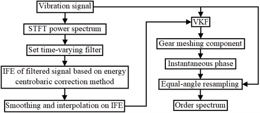
Step 1: The time-varying filter is set according to the frequency change of the meshing component harmonic, which changes obviously, and the energy is outstanding in the STFT power spectrum of the vibration signal. Then vibration signal is filtered.
Step 2: Obtaining estimation of gear meshing frequency from filtered signal based on energy centrobaric correction method.
Step 3: Considering the transmission system is an inertial system, smooth IFE by cubical smoothing algorithm with five-point approximation, apply interpolation to the smooth IFE for obtaining the IFE at all sampling moments.
Step 4: According to the IFE, the harmonic of gear meshing component is extracted from the original signal by VKF, and the instantaneous phase of the reference shaft is obtained according to the transmission ratio.
Step 5: According to the instantaneous phase, the equal-angle resampling moment is calculated, and the original vibration time domain signal is converted into the angular domain signal by interpolation, then the order spectrum is obtained by FFT.
4. Simulation analysis
In order to validate proposed algorithm, the simulated signal can be generated according to the gearbox vibration model given in Refs. [9, 17]:
where is the total number of tooth-meshing harmonics, is the instantaneous angle of gear shaft at time instant , is the number of gear teeth, and are the amplitude and initial phase of the th meshing harmonic, and are the amplitude and phase modulation functions, respectively. represents the measurement noise.
Without loss of generality, according to Eq. (7), the specific value of the simulation theoretical vibration signal can be expressed as Eq. (8). The sampling frequency is set to 2560 Hz and the total time is 12 s:
where the parameter values of Eq. (8) are listed in Table 1, and changes according to Eq. (9). As the shaft of is considered as reference shaft, all first order characteristic orders are calculated in Table 1. To study the immunity to noise of energy centrobaric correction method, add different degrees Gaussian noise to for generating noise signals and :
The STFT power spectra are obtained with short-time Hanning window, where the duration 0.5 s, and the overlap rate is set to 0.125 s. The STFT power and amplitude spectrum of with SNR of 0 dB, are presented in Fig. 2(a). The STFT power and amplitude spectrum of the strong noise signal with SNR of –7 dB, are presented in Fig. 2(b). In amplitude spectrum of Fig. 2(b), only in the time of 4 s-7 s, characteristic frequency components , 2 (14.5, 29 Hz), (317, 634, 951, 1268 Hz), (92 Hz) can be discriminated obviously. But the other spectral lines are blurred, and the sidebands of most components are unrecognizable.
Table 1Parameter values of the simulated signal
Signal component | ||||
Tooth number | – | 100 | 29 | 36 |
Instantaneous rotating frequency | ||||
Instantaneous meshing frequency | – | |||
Instantaneous angle of shaft | 0.2188 | 0.29 | ||
Rotating order / | 4.5714 | 1 | 0.29 | |
Meshing order / | – | 100 | 29 | 10.44 |
Under 0.8, 512, 5 Hz and the corrected spectral line number is extended to 7 [12], IFE of based on energy centrobaric correction method is shown in Fig. 2(c). Although the amplitudes of the meshing harmonic components contained in are similar and effect of slight noise, the vast majority of IFE points fall on 2, as Fig. 2(c) shown. The IFE points of are presented in Fig. 2(d). As can be seen by comparing (c) and (d) of Fig. 2, the energy center correction method will not be able to perform instantaneous frequency estimation under the influence of strong noise.
Fig. 2Results of IFE under different noise conditions based on energy centrobaric correction method
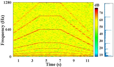
a) STFT power and amplitude spectra of , SNR of 0 dB
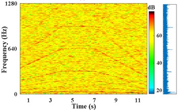
b) STFT power and amplitude spectra of , SNR of –7 dB
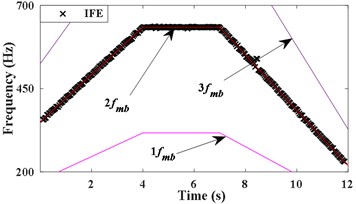
c) IFE of
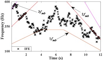
d) IFE of
The frequency of points at 0.25 s, 3.875 s, 7.125 s, and 11.75 s correspond to 370 Hz, 634 Hz, 634 Hz, and 235 Hz, respectively, are picked approximately from the STFT power spectrum of Fig. 2(b) by combining the amplitude spectrum. As shown in Fig. 3(a), in the periods of 0 s-3.875 s, 3.875 s-7.125 s, and 7.125 s-12 s, linear interpolation is carried out separately at interval of 0.25 s to obtain . The instantaneous rotation frequency of the , which can be calculated according to .
As shown in Fig. 3(a), the passband cutoff frequencies of the time-varying filter are set to ,, the stopband frequencies of filter are set to . determines the width of the filter range, the appropriate makes the second harmonic of meshing component of included in the passband range, and makes other components outside of the range. The time varying filter is set to filter the strong noise signal . The STFT spectrum of the filtered signal and the obtained IFE by energy centrobaric correction method are shown in Fig. 3(b). Fig. 3(c) shows the results of smoothing and interpolation on IFE.
Fig. 3IFE of x2 based on time-varying filter and energy centrobaric correction method
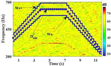
a) Passband cutoff frequency of filter
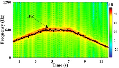
b) IFE of the filtered signal
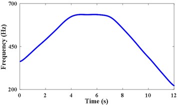
c) Data smoothing and interpolation
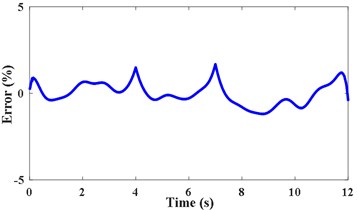
d) RE of IFE
The relative error (RE) and root mean square relative error (RMSRE) are applied to evaluate estimation precision of IFE:
where TIF represents the theoretical instantaneous frequency and denotes the total length of the data. The relative error of IFE is shown in Fig. 3(d). The RMSRE and of IFE are less than 0.004 % and 1.6 %, respectively. It demonstrates that the proposed method can achieve high precision of IFE under strong noise.
According to the IFE in Fig. 3(c), the second harmonic of extracted from by VKF is shown in Fig. 4(a). The STFT energy spectrum of this component is shown in Fig. 4(b). It can be seen that VKF suppresses other harmonic components effectively. According to Fig. 4(a) and Eq. (6), the shaft instantaneous phase of is calculated as shown in Fig. 4(c). The error between the obtained phase and the theoretical phase is shown as a line of “Error of filtered signal by VKF” in Fig. 4(d). According to Fig. 3(c) and Eq. (5), the integration is performed directly. The error between the obtained reference shaft phase based on IFE integration and the theoretical phase is shown as the line of “Error of integration on IFE”. According to Fig. 4(d), the phase error based on the VKF filtered signal does not exceed 0.08 rad, and the phase error of integrating on the IFE directly is nearly 0.3 rad. This also verified the calculated reference shaft phase information based on the VKF filtered signal is more accurate than phase information obtained by integrating on IFE directly.
Fig. 4Obtain accurate phase information of the reference shaft based on VKF
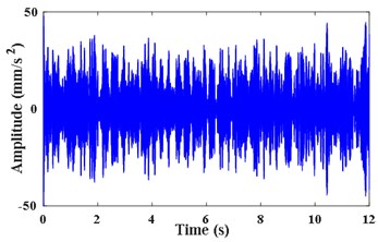
a) Extracted meshing component by VKF

b) STFT power spectrum of component
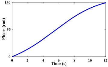
c) Instantaneous phase of the reference shaft
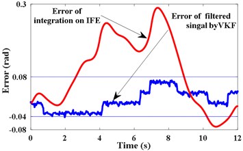
d) Errors of phase estimation
Fig. 5The order spectra of x2 based on proposed method and COT
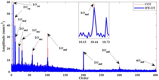
As shown by the blue IFE-OT line in Fig. 5, the order spectrum of is obtained with reference phase information of Fig. 4(c). The orders of 1, 2 (4.57, 9.14), the orders of 1, 2, 3 (100, 200, 300), the orders of , 1, 2, 1, 2 (29, 58, 10.4, 20.9 ), and sidebands of 1 (10.15, 10.73) can be distinguish clearly. The red line shown in Fig. 5 is the order spectrum of the computed order tracking (COT) based on the theoretical phase. It can be seen that the order spectrum of the two kind of methods are same basically.
5. Application to the gear fault detection
Multi-stage gearbox test bench is used for experiment to verify the effectiveness of the proposed method. Test bench drive system is shown in Fig. 6(a) and the last stage meshing gear is set to have a broken tooth failure. As show in Fig. 6(b), inverter motor drives the gearbox system, which consisted by one stage of planetary gearbox and two stages of fixed shaft gearbox, faulty gear is . Torque load is set to 41 N·m, which is applied by magnetic powder brakes. The sampling frequency is 5120 Hz, and the acquisition time is 15 s. Characteristic orders are listed in Table 2, where , , denote the rotating order of motor, sungear, planet carrier, respectively, and denote the meshing order of planetary gearbox and fixed-shaft gearbox, respectively. The gear fault characteristic order is (1), and its corresponding meshing order is (36).
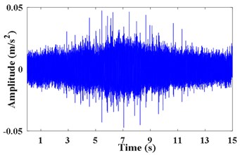
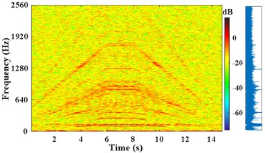
The pulse signal of the motor shaft is measured by tachometer as shown in Fig. 7(a). The vibration acceleration signal x3 measured on the bearing seat cover beside the failed gear is shown in Fig. 7(b). Fig. 7(c) presents the STFT power spectrum of . It can be observed that the principal components are time-varying and fluctuant along with the rotating frequency. The actual frequency of the planetary meshing second harmonic can be obtained according to the transmission ratio and rotating frequency of shaft. As presented in Fig. 7(d), the IF of planetary meshing second harmonic is estimated via the energy centrobaric correction method. The IFE points coincide with 2 on the whole, except for the times of start and end sampling. These abnormal points of IFE are caused by the low vibration energy and these harmonic components interfering with each other mutually at low speeds. It is considered that SNR of the measured signal is not smaller enough overall.
Fig. 6Introduction of multi-stage gearbox test bench
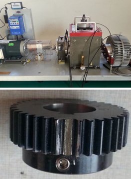
a) Arrangement of test bench and faulty gear
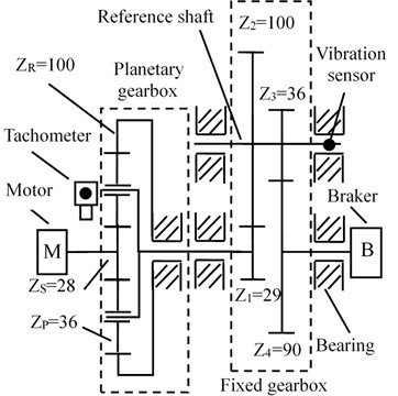
b) The structure of system and placement of sensors
Table 2Characteristic orders of gearbox
Items | Planetary gearbox | Fixed gearbox | ||||||||
Tooth number | 28 | 36 | 100 | 29 | 100 | 36 | 90 | |||
Shaft rotating order / | 15.7 | 3.45 | 3.45 | 1 | 0.4 | |||||
Meshing order / | 344.8 | 100 | 36 | |||||||
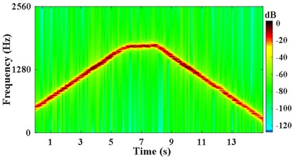
As shown in Fig. 8(a), in order to verify the effectiveness of the proposed method under strong noise, noise signal is obtained by adding Gaussian white noise SNR of 1 dB into the original vibration signal . The STFT energy spectrum and the partial amplification amplitude spectrum of are shown in Fig. 8(b). From the amplitude spectrum, it can be seen that the frequency lines are blurred. As shown in Fig. 8(c), The points of IFE partial overlap with the IF of planetary gear meshing harmonic components 1, 2, 3 and the IF of the first stage of the reducer meshing 1. So, IFE of single meshing harmonic component cannot be obtained from by energy centrobaric correction method directly.
Fig. 7Measured signal and IFE based on energy centrobaric correction method
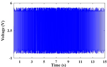
a) Tacho pulse of inverter motor shaft
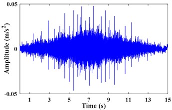
b) Vibration acceleration signal
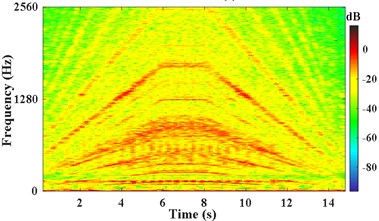
c) The STFT power of
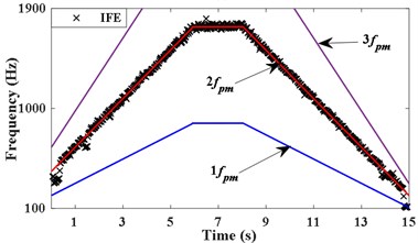
d) IFE of
Fig. 8IFE of high noise signal based on energy centrobaric correction method
a) Noise signal
b) The STFT power and amplitude spectrums of
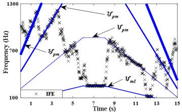
c) IFE of
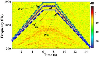
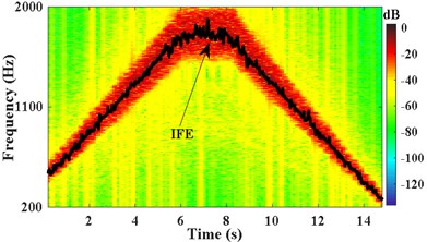
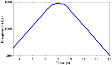
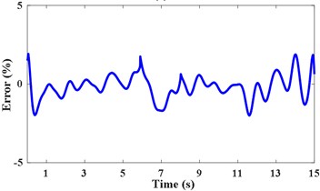
Pick up two points of each period in the STFT power spectrum by combining the amplitude spectrum in Fig. 8(b). The corresponding frequency at times of 0.75 s, 6.05 s, 8.15 s, and 13.65 s are 612 Hz, 1744 Hz, 1744 Hz, and 516 Hz, respectively. The passband cutoff frequencies of the time-varying filter are shown in Fig. 9(a). The STFT power spectrum of the filtered signal is shown in Fig. 9(b), IFE of the filtered signal is acquired by energy centrobaric correction method. The result of smoothing and interpolation on the IFE is shown in Fig. 9(c). The relative error of IFE and the actual planetary gear meshing second harmonic frequency is shown in Fig. 9(d). The and RMSRE of IFE are less than 2 % and 0.003 %, respectively.
According to the IFE in Fig. 9(c), the planetary gear meshing second harmonic is obtained by the VKF. The STFT power spectrum of this harmonic is shown in Fig. 10(a). The instantaneous phase of the reference shaft, is shown in Fig. 10(b).
Fig. 9IFE of high noise signal based on time-varying filter and energy centrobaric correction method
a) Passband cutoff frequency of filter
b) IFE of filtered signal
c) Data smoothing and interpolation
d) RE of IFE
Fig. 10Instantaneous phase of reference shaft based on VKF
a) STFT power spectrum of component
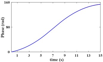
b) Instantaneous phase of reference shaft
As Fig. 11 IFE-OT shown, Order spectrum of is given in, based on Fig. 10(b). It can be distinguish clearly from IFE-OT based on proposed method: the orders of motor rotating 1, 2, (15.7, 31.5, 47.1), planetary meshing characteristics meshing characteristics of /, 1, 2, 3 (100, 200, 300 ). The / meshing orders 1-5 (36, 72, 108, 144, 180) of IFE-OT are anastomosis to the order features of COT. But, as the faulty gear is located in the low-speed stage of the system, the vibration energy of the faulty gear generated is weaker than the vibration energy of high-speed normal gear generated. Therefore, relying solely on the order spectrum, it is hard to directly determine whether gear is faulty.
In order to further verify the effectiveness of the proposed methods, the proposed tacholess order tracking method is further combined with the Fast-kurtogram technique [25] to detect the fault of gearbox. The parameters of appropriate filter are selected and the vibration in the angular domain is filtered. Fig. 12(a) is kurtosis diagram of . The central order and the optimal level of the optimal analysis can be determined as 234 and 5level. The square envelope spectrum is shown in Fig. 12(b). It can be seen that the characteristic order of the reference shaft (1) and its harmonics (2-20) are quite abundant. The frequency change of the modulation component with the largest energy is the same as the change of the frequency of the reference shaft, thereby verifying that the fault gear is on the reference shaft. Comparing the normal gear order (100) with the fault gear order (36) in Fig. 11, the orders corresponding to meshing of gear (36) and its sidebands (34, 35, 37) in the partial enlarged view are obvious. No significant sidebands appeared on either side of the meshing order (100). These characteristics indicate that gear is a faulty gear.
Fig. 11The order spectra of x4 based on proposed method and COT
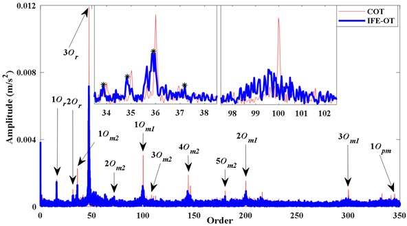
Fig. 12Diagnosis the location of the fault gear
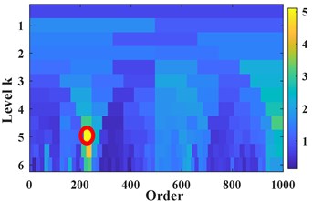
a) Fast kurtosis spectrum of
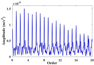
b) Filtered envelope spectrum
6. Conclusions
Aiming at the shortcomings of energy centrobaric correction method, we proposed a tacholess order tracking method based on time-varying filter and energy centrobaric correction method. The time varying filter limits the frequency estimation to a specific range that varies over time. The energy centrobaric correction method is adopted to estimate frequency in this range, thereby overcoming the drawback of sensitive to strong noise. Simulations and experiments verify the accuracy of IFE based on proposed method. The obtained order spectrum by the method is in agreement with the order spectrum by COT to a considerable extent. In addition, it is demonstrated that the proposed method can be further combined with other signal processing technique, such as Fast-kurtogram, etc., to extract the feature of fault of mechanical systems under multi-linear fluctuation without tachometer. The proposed tacholess order tracking technology may be of great application value, especially in the vibration condition monitoring and fault diagnosis of the traditional mine hoisting gearbox.
References
-
Shuiqing X., Ke Z., Yi C., et al. Gear fault diagnosis in variable speed condition based on multiscale chirplet path pursuit and linear canonical transform. Complexity, Vol. 2018, 2018, p. 1-8.
-
Antoni J., Bonnardot F., Raad A., et al. Cyclostationary modelling of rotating machine vibration signals. Mechanical Systems and Signal Processing, Vol. 18, 2004, p. 1285-1314.
-
Li Fugu The Mine Transportation and Ascend. China Mining University Press, 2007.
-
Luo J., Zhang S., Zhong M., et al. Order spectrum analysis for bearing fault detection via joint application of synchrosqueezing transform and multiscale chirplet path pursuit. Shock and Vibration, Vol. 2016, 2016, p. 2976389.
-
Fyfe K. R., Munck E. D. S. Analysis of computed order tracking. Mechanical Systems and Signal Processing, Vol. 11, Issue 2, 1997, p. 187-205.
-
Wang Y., Xu G., Zhang Q., et al. Rotating speed isolation and its application to rolling element bearing fault diagnosis under large speed variation conditions. Journal of Sound and Vibration, Vol. 348, 2015, p. 381-396.
-
Wang Y., Xu G., Luo A., et al. An online tacholess order tracking technique based on generalized demodulation for rolling bearing fault detection. Journal of Sound and Vibration, Vol. 367, 2016, p. 233-249.
-
Wang J., Peng Y., Qiao W. Current-aided order tracking of vibration signals for bearing fault diagnosis of direct-drive wind turbines. IEEE Transactions on Industrial Electronics, Vol. 63, Issue 10, 2016, p. 6336-6346.
-
He G., Ding K., Li W., et al. A novel order tracking method for wind turbine planetary gearbox vibration analysis based on discrete spectrum correction technique. Renewable Energy, Vol. 87, 2016, p. 364-375.
-
Fernandez-Vazquez A., Dolecek G. J. Generalized Chebyshev filters for the design of IIR filters and filter banks. Circuits Systems and Signal Processing, Vol. 33, Issue 7, 2014, p. 2237-2250.
-
Peng F., Yu D., Wu C. Self-adaptively time-varying filter based order tracking method and its application in gearbox fault diagnosis. Journal of Mechanical Engineering, Vol. 48, Issue 7, 2012, p. 77-85.
-
Ding K., Jiang L. Energy centrobaric correction method for discrete spectrum. Journal of Vibration Engineering, Vol. 14, Issue 3, 2001, p. 354-358.
-
Yang Z., Ding K., Qian L. Novel method of order tracking analysis based on spectrum correction. Journal of Mechanical Engineering, Vol. 45, Issue 12, 2009, p. 41.
-
Deng L., Fu W. N., Dong S. J., et al. Tacholess Vold-Kalman order tracking of rotating machinery. Journal of Vibration and Shock, Vol. 30, Issue 3, 2011, p. 5-9.
-
Lin H., Ding K. A new method for measuring engine rotational speed based on the vibration and discrete spectrum correction technique. Measurement Journal of the International Measurement Confederation, Vol. 46, Issue 7, 2013, p. 2056-2064.
-
He G., Ding K., Li W., et al. A novel Order tracking analysis for wind turbine planetary gearbox vibration based on meshing frequency and spectrum correction. Renewable Energy, Vol. 87, 2016, p. 364-375.
-
Zhao M., Lin J., Wang X., et al. A tacho-less order tracking technique for large speed variations. Mechanical Systems and Signal Processing, Vol. 40, Issue 1, 2013, p. 76-90.
-
Wang T., Liang M., Li J., et al. Rolling element bearing fault diagnosis via fault characteristic order (FCO) analysis. Mechanical Systems and Signal Processing, Vol. 45, Issue 1, 2014, p. 139-153.
-
Schmidt S., Heyns P. S., De Villiers J. P. A tacholess order tracking methodology based on a probabilistic approach to incorporate angular acceleration information into the maxima tracking process. Mechanical Systems and Signal Processing, Vol. 100, 2018, p. 630-646.
-
Hu Y., Tu X., Li F., et al. An adaptive and tacholess order analysis method based on enhanced empirical wavelet transform for fault detection of bearings with varying speeds. Journal of Sound and Vibration, Vol. 409, 2017, p. 241-255.
-
Guo Y., Chen X., Wang S., et al. Wind turbine diagnosis under variable speed conditions using a single sensor based on the synchrosqueezing transform method. Sensors, Vol. 17, 5, p. 1149-1163.
-
Emresoy M. K., El-Jaroudi A. Iterative instantaneous frequency estimation and adaptive matched spectrogram. Signal Processing, Vol. 64, Issue 2, 1998, p. 157-165.
-
Boashash B. Estimating and interpreting the instantaneous frequency of a signal. I. Fundamentals. IEEE Proceedings, Vol. 80, Issue 4, 1992, p. 540-568.
-
Herlufsen H., Gade S., Konstantin-Hansen H., et al. Characteristics of the Vold-Kalman order tracking filter. IEEE International Conference on Acoustics, Speech, and Signal Processing, 2000.
-
Antoni J. Fast computation of the kurtogram for the detection of transient faults. Mechanical Systems and Signal Processing, Vol. 21, Issue 1, 2007, p. 108-124.
Cited by
About this article

This work was supported by the Henan Province Science and Technology Project (Grant No. 172102210021), Henan Universities Key Research Projects (Grant No. 19A440007), Doctoral Funds of Henan Polytechnic University (Grant No. B2017-28) and Foundation of innovative research team of Henan Polytechnic University (Grant No. T2017-3). The authors would like to thank the reviewers for many valuable comments and suggestions.
