Abstract
A set of automatically feeding probe system which can operate independently is designed. It can be widely used in the independent development of most atomic force microscope scanning system. In the approximation process, by VB serial communication, the command is send to control ARM to collect AFM micro-cantilever deflection signal, which is transmitted to the computer for display and analysis, real-time monitor the force between the probe and the sample, and ultimately realize the automatic approximation of probe. The system can be used in combination with various related atomic force microscopy devices, and achieve the goal of personalized multi-function detection.
1. Introduction
Atomic force microscope (AFM) [1] is a scanning probe microscope with atomic resolution level, which uses micro cantilever as a force sensor. When sample is scanned under the probe tip, atomic force between the probe tip and sample will cause the deformation of micro cantilever. By detecting the changes of micro cantilever corresponding to the position of each scanning point, we can get the surface morphology of the samples.
Advantages of AFM: It has a high quality imaging, and it can format 3-D real-time imaging. The sample preparation is simple under the environment of air or liquid, it has been widely used in materials, physics, chemistry, biology, medicine and other Nano scientific research fields [2].
The AFM principle and atomic force law [2] show that only the distance between the AFM probe and the surface of the sample reaches the nanometer level, the sample surface atom and microprobe can produce stable atomic force which makes microcantilever deflection. The sample approximates to microprobe, until atomic force of between the sample surface and microprobe get into stable state which called the AFM approximation state. If this process is adjusted by the manual mechanical device, it is difficult to reach the positioning accuracy of nanometer level. If the distance adjusted is not enough, the distance is outside a certain range, which is between the microprobe of AFM and sample surface, it is unable to make the microcantilever work normally. If the distance adjusted is too deep, it often makes the microprobe and sample surface contact directly, which leads to the damage of the sample surface or microprobe.
In literature [3-7], the coarse feeding probe system is adjusted by manual mechanical device, then the fine feeding probe system is adjusted by piezoceramic actuators. The method exists shortcoming that it will lead to the microprobe and the sample surface contact and scratch the surface of the sample or damage microprobe when the stroke of the manual coarse feeding probe is oversize; And that the stroke of the manual coarse feeding probe is too small, after the fine feeding probe is carried out, the distance between the probe and the sample surface can’t reach nanometer level.
In literature [1], the manual mechanical feeding probe is improved and presents a deflection of microcantilever which is converted into a voltage corresponding to the value, then the host computer sends instruction to control the nanometer resolution stepper motor which drives vertical mounting electrical-controlling move apparatus to realize automatically feeding probe, at the same time, the microcantilever offset corresponding to the voltage value is collected by A/D converter as a feedback system. The collected voltage value is equal to the preset voltage value, the operation of stepper motor is stopped, automatically feeding probe is ended.
In literature [1], a set of automatically feeding probe system which can independently operate, is designed. During the approximation process, the control instruction which is sent by serial port, controls MCU to collect AFM microcantilever deflection signal which is transmitted to the computer. Then the computer displays and analysis the signal, and monitors the force between the probe and the sample In real time, and automatically feeding probe is realized at the end.
In view of the above problems, after the control method of AFM automatically feeding probe system is studied and analyzed in detail, the comprehensive method is utilized, that is, manual mechanical control, non-contact displacement sensor, electrical-controlling move apparatus and piezoceramic actuators. According to the above, AFM automatically feeding probe system is designed.
2. Work principle
AFM automatically feeding probe system is a device which can automatically adjust the distance between the AFM probe and the sample surface. Overall system structure diagram is as shown in Fig. 1. The system mainly includes: electrical-controlling move apparatus (stepper motor, stepper motor driver), coarse adjusting knob, non-contact displacement sensor, a sample platform and the software drive etc.
Fig. 1The structure principle diagram of the automatically feeding probe system
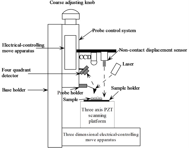
Before scanning and imaging of the AFM, it is necessary to approximate the scanning probe of AFM to the sample surface and reach the working state of atomic force, so that the scanning and imaging work can carry out. The probe of AFM is far away from the sample surface during the absence of an automatic probe. The AFM probe and the probe base are arranged at the end of the direction of the probe regulating system, and the sample platform is installed on the PZT scanning platform.
The system through the acquisition of non-contact displacement sensor to measure if the distance from the AFM probe at the bottom to the sample table is greater than the set distance , if it is more than , at first, coarse adjustment knob is used for coarse adjustment, by adjusting the coarse knob, control the overall downward movement of the AFM probe holder and the electrical-controlling move apparatus, when the distance between the AFM probe and the sample is less than or equal to , the system gives an alarm, the operation staff stops manual coarse adjustment. Then the probe is fine adjusted by the electrical-controlling move apparatus. MCU controls automatically according to the measured values of the non-contact displacement sensor, when the distance between the AFM probe and the sample surface reaches nanometer level through the PC software set, the fine probe adjusted is stopped by electrical-controlling move apparatus. After the probe is fine probe adjusted, in order to further correct the fine probe adjusted, according to the distance between the AFM probe and the sample measured by the non-contact displacement sensor, the direction piezoceramic actuators is started again for the compensation of the fine probe adjusted. At the same time, the output signal of four quadrant photoelectric detector is sampled by the A/D, when the feedback signal reaches the preset value, the direction piezoceramic actuators is stopped, and the automatically feeding probe process has finished as well.
2.1. Design of automatic probe system
(1) The choice of electrical-controlling move apparatus.
The system used vertical placement method of electrical-controlling move apparatus to realize the probe in the vertical direction of the lift, and the electrical-controlling move apparatus is driven by the stepper motor to realize the automatic adjustment of the probe. The system chooses the HA-MTS201 type of electrical-controlling move apparatus to control the auto feeding probe system.
The main characteristics of HA-MTS201: Fine grinding screw drive, cross roller guide; The structure is compact, the overall dimension is small and exquisite, with high resolution; With standard computer communication interface; photoelectric switch is set zero, both ends set censored position switch. The technical parameters of DP-MTS202 are shown in Table 1.
Because of the step angle of stepper motor is 180 degrees, the screw rod guide is 1mm, in order to improve the control precision of the AFM automatic probe system, the system uses stepper motor driver of SH-20403, which is subdivided by 64 segments, and makes the minimum displacement of the electrical-controlling move apparatus reach 78 nm.
Table 1Technical parameters of HA-MTS201
Parameter name | Parameter | Unit |
Stroke | 30 | mm |
Table size | 65×65 | mm |
Guide rail | V shaped guide rail+Cross roller | |
Lead screw guide | 1 | mm |
Resolution ratio | 0.000078 | mm |
Maximum speed | 10 | mm/s |
Repeated positioning accuracy | <0.003 | mm |
Step angle | 1.8 | ° |
Center of the load | 10 | Kg |
(2) Selection of non-contact displacement sensors.
ZLDS/N-100 is selected by the system, which has the nanometer level resolution non-contact displacement sensor, and measure the distance between the probe holder and the sample table. ZLDS/N-100 has a range of 100 μm and a resolution of 15 nm. The initial measurement distance of the ZLDS/N-100 Nano scale displacement sensor is 3 mm, which has a wide application range for the measured body, such as metal, semiconductor and glass. The sensor can be easily connected with the existing design, and has a larger reference distance, and the nanometer level displacement sensor can be equivalent to a high resolution capacitance sensor. For fixed point measurement, vibration measurement, surface profile measurement, ZLDS/N-100 Nano displacement sensor is an ideal measuring tool. Its specific parameters are shown in Table 2.
Table 2Technical parameters of ZLDS/N-100
Parameter name | Parameter | Unit |
Range | 100 | μm |
Resolving power | 15 | nm |
Repeatability | ±75 | nm |
Permissible surface reflectance | 4-100 % | |
Sensor probe reference distance | 3 | mm |
Power supply voltage | ±12 | V |
Controller interface | RS-232 |
3. Control system design of auto feeding probe
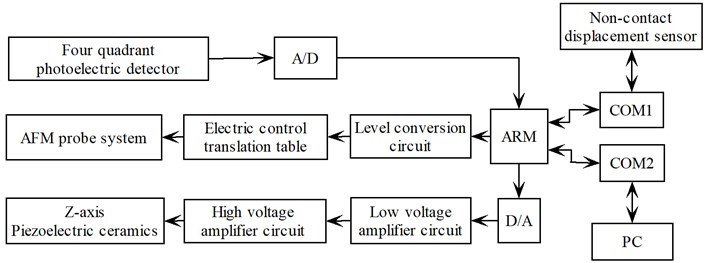
The principle diagram of the automatically feeding probe system is shown in Fig. 2. The system software mainly includes two parts of the upper machine and the lower machine. The lower machine takes ARM chip as the main controller, which mainly completes the control of the electronic control translation table, and the control of direction piezoceramic actuators, and collects the output of the return signal of the four quadrant photoelectric detector. The upper machine uses the control software of VB development through the serial port to send control instructions, data receiving and processing analysis, etc.
Fig. 2The principle diagram of the automatic control system
4. Design of software protocol
Based on command button of PC software, computer sends control instruction to ARM through serial port. After MCU receives control instruction, it executes corresponding control operation. According to the above operation, the double machine communication is involved. Ensuring accuracy of system control and correctness data transmission, a series of communication protocols are required. According to the system agreed, basing on a constant length of 10 bytes all instruction and data are transmitted.
1. Format of control instruction sent by computer (Table 3).
Table 3Format of control instruction sent by computer
Instruction | xx | xx | xx | xx | XX | XX | 99H | 99H |
Serial communication protocol: All data are hexadecimal data in frame format. Where instruction occupies 2 bytes; xx represents data, which occupies 4 bytes; Occupying 16 bits (namely 2 bytes), XX is check sum which is cumulative sum of all data before XX. High byte is former, low byte is at the back, and 99H 99H is the end of frame format.
2. Detailed instruction.
(1) Automatically feeding probe is started by non-contact displacement sensor.
AA 01 xx xx xx xx XX XX 99 99, where, ”xx xx xx xx” is distance of automatically feeding probe, which is hexadecimal digits and occupies 4 bytes. “XX” is check sum, which is the same as above.
For example: AA 01 00 00 01 23 00 CF 99 99 00 CF = AA + 01 + 00 + 00 + 01 + 23, the displacement of automatically feeding probe is 291 nm by non-contact displacement sensor.
(2) Automatically feeding probe is started by non-contact displacement sensor:
AA 02 xx xx xx xx XX XX 99 99.
(3) Automatically feeding probe is stopped:
AA 03 xx xx xx xx XX XX 99 99.
5. Conclusions
This system takes advantage of the non-contact displacement sensor to detect the displacement between the probe and the sample, and exempts from the inconvenience caused by the adjustment of the optical path of the general reflection type AFM. The scan range of the maximum plane is 200 μm×200 μm, the longitudinal is 2-10 μm, the horizontal resolution is less than 1 nm, and the vertical resolution is less than 0.01 nm. The data exchange of between ARM and computer is realized by serial port, the design can achieve high precision positioning control in three direction, and greatly expand the application limit of AFM. The design can also be applied to the research and design of various atomic force microscopes, and it can use the non-contact displacement sensor to realize the automatic approximation of the probe and the sample.
References
-
Zhou Kaibo, Huang Maomao, Yin Yujuan. Design and application of auto feeding system for atomic force microscopy probe. Science and Technology Review, Vol. 271, Issue 8, 2009, p. 43-45.
-
Xi N., Fung C. K. M., Yang R. G., Seiert Sinha K., Lai K. W. C., Sinha A. A. Bionanomanipulation using atomic force microscopy. IEEE Nanotechnology Magazine, Vol. 4, Issue 1, 2010, p. 9-12.
-
Hofmann N., Hausotte T., Jager G., et al. Measurements with an atomic force microscope using a long travel nanopositioning and nanomeasuring machine. The 4th IEEE Conference on Nanotechnology, Munich, Germany, 2004, p. 183-185.
-
Cappella B., Dietler G. Force-distance curves by atomic force microscope. Surface Science Reports, Vol. 34, Issue 10, 1999, p. 1-10.
-
Binnig G., Quate C. F., Gerber C. H. Atomic force microscope. Physical Review, Vol. 56, Issue 9, 1986, p. 930-933.
-
Binnig G., Rohrer H. Scanning tunneling microscope. Helvetica Physica Acta, Vol. 55, Issue 4, 1982, p. 726-735.
-
Tian Xiaojun, Wang Yuechao, Xi Ning, Dong Zaili, Li Wenrong. Actuator actuating and probe positioning of robotic nanomanipulation system. Chinese Journal of Scientific Instrument, Vol. 28, Issue 7, 2007, p. 1223-1228.
About this article

This work was supported by International Science and Technology Cooperation Program of China (No. 2012DFA11070), National Natural Science Foundation Program of China (No. 61176002), EU FP7 (ECROBOT No. 318971; BioRA No. 612641), Jilin Provincial Science and Technology Program (No. 201215136, No. 20140414009GH); The Education Department of Jilin Province Science and Technology Program (No. 201554).
