Abstract
In the work traditional and innovative methods for constant current LED drivers have been studied. The low-cost solutions for energy effective low lighting flicker current regulation have been proposed. The advantage is due to fact that auxiliary switch-mode regulator converts only small part of output power. The proposed solution can be used in LED drivers to reduce pulsations of the light flux, as well as in driverless AC LED modules to monitor LED currents and/for power correction.
1. Introduction
In the lighting market, there is a dramatic shift to light devices based on ultra-bright LEDs due to their greater efficiency and durability, which saves considerable energy costs and the cost of ownership. The changes are so rapid that analytical agencies predict [1-3] that LED lighting will completely displace inefficient incandescent lamps and fluorescent lamps from the market by 2024. No less important and more important than LEDs, the element in the lighting devices is an electronic power source for the lamp over bright LEDs (LED driver, LED driver), which determines the reliability of the entire lamp, its lifespan and overall efficiency. To reconcile the power supply with the LEDs, additional electronic converters are used power supplies for the LEDs.
No less important than LEDs, an element in the lighting devices is an electronic power supply of a lamp on extra bright LEDs (LED driver, LED driver), which determines the reliability of the entire lamp, its lifetime and overall efficiency. To reconcile the power supply to the LEDs, additional electronic power supplies for LEDs are used.
According to the forecasts of the US Department of Energy, in view of the drop in the cost of semiconductor LEDs, the share of the power source in the structure of the total cost of lighting will grow, amounting to a significant 20 % of all costs by 2020. In other words, in the cost of lighting, the costs for the LED driver will be equal to the costs for the LEDs themselves!
Therefore, the actual task is to reduce the cost of LED drivers while maintaining all other qualities and functional characteristics. And this, in addition to directing tasks to increase efficiency and reduce the size.
A feature of LEDs is that the emitted light flux is almost directly proportional to the current of the LED, which in turn is very sensitive to the voltage across the diode. Therefore, in order to maintain pulsations of the light flux, it is a common practice to apply current stabilization schemes.
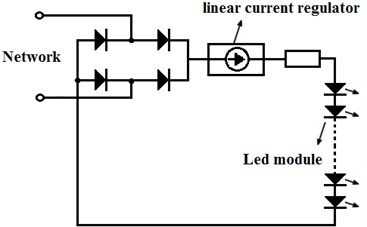
For example, for a Cree LED at 10 % of the voltage deviation from an average of 3.5 V, the current and therefore the luminous flux deviate from its average by 46 %. Fig. 1 shows the circuit [4-6] of the simplest AC LED Module on a linear current regulator: here, the diode bridge rectifies the input AC mains current, then from the output of the diode bridge through the linear current regulator, the series-connected LEDs are powered. The scheme is simple and inexpensive to implement, but a significant drawback is that the efficiency of the LED module is low, typically about 70 %; without an input energy storage (for example, an electrolytic capacitor), the LED module will have a 100 % ripple ratio; the power factor and harmonic distortion are in accordance with the EMC standards for medium power devices.
When designing LED lamps, it is necessary to take into account the fact that light devices are subject to certain requirements [7] for electromagnetic compatibility (EMC), safety and quality of light radiation. For example, in Russia there are requirements to the coefficient of pulsation of the light flux, which should not exceed:
• 10 % for pre-school institutions, premises where high-precision work is carried out, and rooms where there is a lack of stroboscopic effect;
• 5 % in the rooms for working with computer equipment, that is offices.
In December 2009, the US Energy Department issued the final version of the EnergyStar program, which requires that LED drivers for households have a power factor of at least 0.7, and for industrial applications no less than 0.9. The linear stabilizer can be used in LED drivers with power factor corrector (PFC) to control the current of the LEDs in order to mitigate the line ripple at the output of the PFC. Then the complexity of the device increases, but the efficiency is greatly improved.
Fig. 1Circuit of the simplest AC LED module
2. The overview of the state of the art
To date, many engineering solutions have been worked out to meet the LED sources with all the main certification standards [8].
Power impulse converters are used to stabilize the current LEDs and increase the efficiency. Pulse converters provide high efficiency, respectively small size, but the disadvantage is the complexity of the devices and the generation of interference. In addition, impulse converters are also used to correct the power factor and harmonics distortion.
Fig. 2 shows a typical block diagram of an LED driver.
Fig. 2Typical block diagram of an LED driver
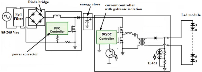
A power equalizer, an energy storage and a current regulator consistently included to the output of the diode bridge. The current controller is either a buck, a boost or, more rarely, a half-bridge resonant converter, whose task is to stabilize the output voltage/current for powering the LEDs. Qualitative current stabilizers that meet the requirements for electromagnetic compatibility, safety, reliability of the LED lamp, high efficiency, contain all these structural components. Moreover, the overall efficiency of the device is 92 %, where 96 % typical corrector efficiency with the diode bridge, and 96 % typical efficiency of the regulator. The disadvantage of this practice is the complication of the device by the inclusion of an additional current regulator designed to the full rated power of the product, hence the increase in dimensions and the cost of the product. While the price of the solution remains such that not all customers are ready to pay and many choose their cheaper options. So, for developers there is still a lot of work to find cheap solutions to increase the reliability, efficiency and quality of LED drivers.
One possibility is to simplify and reduce the cost of the current stabilization circuit. For example, when the voltage on the LED module is lowered, it is possible to turn off some of the series of LEDs from the LED module so that the voltage on the remaining connected part of the LEDs does not change. Thus, the light flux will decrease only by the relative value of the voltage ripple, that is, if the voltage drops by 10 %, only 10 % of the diodes will be turned off, and then the light flux of the others will not change.
There are other similar solutions based on the switching of LED blocks, some of which are offered on the market in the form of ready-made implementations on microchips.
In the US patent [9], the LED current control device consists of (see Fig. 3): rectifier and/or corrector 2 for converting AC power to rectified power supply current connected to the variable network; sequentially connected to the output of the rectifier of the first 11 and second 12 LED blocks, each of which includes a plurality of LEDs; a control section 21 that controls the bypassing second LED unit to modulate the impedance of the second unit; and the current detection circuit of the LED unit 11. Thus, the current control device is able to monitor and stabilize the current of the first unit 11 at a pulsating voltage at the output of the rectifier 2.
Fig. 3Light-emitting diode driving apparatus
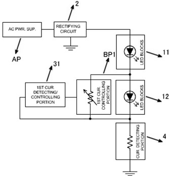
The disadvantages of this device are insufficient efficiency, since the regulating section 21 operates in a linear mode, although the efficiency is higher than in the case of Fig. 3, where the linear regulator operates at full load current. The efficiency of the whole device will be , where is the average fraction of the total power output diverted by the regulator and which is dissipated there. If reaches 5 %, will be equal to 91 %. In general, the efficiency of the device in Fig. 3 may be much worse than in Fig. 4, depending on the solution. There are other similar solutions based on the switching of LED blocks, some of which are offered on the market in the form of ready-made implementations on microchips.
In another US patent [10] (see Fig. 4), an auxiliary converter 30 is used to stabilize the current, calculated for power much less than the power of the conventional stabilizer indicated in Fig. 2.
Fig. 4Hybrid constant current lamp
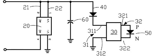
In the hybrid lamp apparatus, the main light-emitting module 40 and the input of the auxiliary converter 30 are connected in series to the output of the rectifier and the power storage unit 60, to the output of which the secondary light-emitting module 50 is connected. The peculiarity of the device is that the auxiliary converter 30, changing the supply current of the secondary LED 50, stabilizes the consumption current at the diode 40 at a given voltage at the output of the accumulator 60. A disadvantage of the device is that the auxiliary converter must conduct the total current of the main LED through itself, but potentially the efficiency may be higher than in the case of Fig. 2 and Fig. 3.
3. The proposed solution
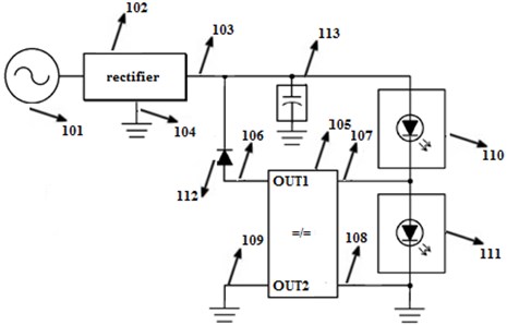
The device as in Fig. 3 would be more efficient if instead of a linear regulator a pulse converter was used to recuperate energy bypassing the second LED unit 12 back to the output of the power rectifier 2. Thus, in the patent application [11], we proposed a “LED current control device”, one implementation of which is shown in Fig. 5 and consists of a rectifier/equalizer 102, the main LED module 110 and the additional LED 111 are serially connected. In order to stabilize the current in the module 110, the auxiliary converter 105 changes the impedance of the additional module 111 so that the converter 105 can regulate the current around the module 111. The advantage is that the converter 105 recovers back to the rectifier output and/or energy storage device 120 most of the diverted power. The power dissipated by the auxiliary converter is , where is the efficiency of the converter 105, the total output power and is the power output from the total power. The total efficiency of the device will be , if we accept 96 %, 96 % and 5 %, will not be much less than 96 %, and basically is determined by the efficiency of the corrector.
Fig. 5Circuit of the LED current control device
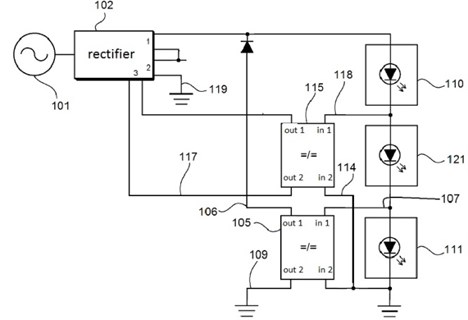
That is, the efficiency of the proposed device is superior to the devices discussed above. In addition, the nominal power of the regulator 105 is less, other things being equal, than in the previously discussed regulator 30 in Fig. 3, since it carries through itself a portion of the rated current of the current of the main LED module 110. In case of large discharges at the output of the rectifier, it is possible to use additional LED groups of an arbitrary number and auxiliary converters corresponding to them, this will allow reducing the power of the auxiliary converters. For example, the circuit in Fig. 6 includes at least two additional LED groups 111 and 121. At a high voltage at the output of the rectifier 102, the second auxiliary converter 115 is turned off so that all of the current flows through the group 121, and the current of the main LED group 110 is controlled by the first recall converter 105. When the voltage at the rectifier output decreases, if the decrease in the impedance 111 no longer compensates for the drop in the output voltage, the second converter 115 is turned on in the control process, and the LED group 111 is shunted during the operation of the second auxiliary converter. It is seen that each auxiliary converter will work only in its section of the output voltage change, correspondingly there will be less power loss during conversion. Thus, for large voltage pulsations on LED assemblies, the inclusion of a large number of additional modules reduces losses and increases the utilization of LEDs. Auxiliary converters can recover energy not only by output rectifier. In Fig. 5 shown that the second auxiliary converter 115 regulates energy to another output 3 of the rectifier 102 to power other LED assemblies, internal rectifier circuits or external connected electrical circuits.
Fig. 6Circuit of the LED current control device
4. Conclusions
The proposed solutions achieve high efficiency and acceptable flickering of the light flux due to the use of impulse converters, which, due to the peculiarities of the circuit solution, regulate small portions of the power from the total power of the devices and thereby introduce small losses.
Auxiliary converters can be designed for low power, so they are not high in cost; scatter low power and their weight and size indicators can be small. And in view of the small dissipated power, the auxiliary converters can be realized as integrated circuits.
References
-
Scale of LED Industrial lighting to reach US$2.9 billion in 2016. 2016, www.ledinside.com/node/24822.
-
Global LED and Smart Street Lighting (2016-2026). 2017, www.prnewswire.com.
-
Global LED And Smart Street Lighting (2015-2025). Vol. 2, 2015, www.northeast-group.com.
-
Lee Yu-Lin Constant Current LED Lamp. Patent US8519631B2, 2013.
-
Van Ha Nguyen Low cost, high power factor, dimmable, monolithic, ac-direct LED driver with on chip step-dimmer for outdoor applications. International Journal on Engineering and Technology, Vol. 8, Issue 6, 2016, p. 414-417.
-
Datasheet FL77944. High Power LED Direct AC Driver. Fairchild Semiconductor, 2016, www.fairchildsemi.com.
-
Bain Jonson, James Lee Solutions for today’s low-power LED lighting trends. 2012, www.fairchildsemi.com.
-
Advances in LED and LED Driver Technology Pave the Way for Significant Reductions in Global Power Usage and Cleaner Environment. Fairchild Semiconductor, 2012, www.fairchildsemi.com.
-
Shuji Muguruma, Wataru Ogura Light-Emitting Diode Driving Apparatus and Light-Emitting Diode Lighting Controlling Method. Patent US8471495B2, 2013.
-
Lee Yu-Lin, Huang Kuo-Chung Hybrid Constant Current Lamp. Patent US2015/0002039A1, 2015.
-
Junusbekov E., Khamitov S. LED Current Control Device. Patent No. 2016/03231, 2016.
About this article

