Abstract
Vibrations appearing in transport chain conveyors cause disadvantageous effects in conveying processes and decrease the durability of chains. In order to investigate these vibrations, a conveyor system with sliding chain made of plastic has been selected. Based on a generalized abstraction of this system, a multi-body simulation model was developed which considers viscoelastic properties of the sliding chain. The model was verified by measurements in the conveyor system. Finally, influencing factors on dynamic behavior were examined in more detail by variant calculations.
1. Introduction
Chain conveyor systems with sliding chains made of plastic are often used for flexible designs of material flow. Modular track profiles, drives, redirections, wheels and slide rails allow an easy adaptation to logistical processes. Due to diverging chain sizes and customizable chain tops, the systems cover a wide range of applications. The sliding chain is guided without lubrication in slide rails, which is demanded in food industry.
If goods slip or tilt in transport processes, this is often due to vibrations of the chain. The chain oscillates mainly longitudinally which can be attributed supposable to friction induced vibrations, polygonal effect and meshing surge at chain wheels, drive stimulation, and chain pitch errors. Vibrations of the conveyor chain result in an oscillating tractive force which can clearly exceed the statically calculated tractive force. These oscillation-induced load peaks can significantly influence the wear of sliding chains [1]. Dynamic effects in slide chain conveyors are largely unexplored and are not taken into account in existing calculation models. So far, calculations are limited to a static tractive force [2, 3].
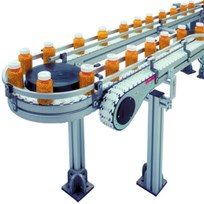
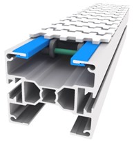
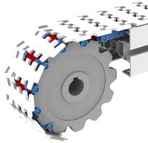
To study vibrations, a conveyor system with sliding chain has been selected (see Fig. 1), which is similar to the systems FlexLink X85 or Bosch Rexroth VarioFlow 90. Based on this, a model is developed and a test conveyor is built for validation.
Fig. 1a) Sliding chain conveyor system in action (source: Bosch Rexroth), its profile with slide rails, b) sliding chain, c) chain wheel with sliding chain
a)
b)
c)
2. Modeling a chain conveyor
The entire chain conveyor is treated as abstraction so that the chain can be transformed to a multi-body model (the chain consists of 540 links). Since the chain is a multi-body system with many degrees of freedom that cannot be solved analytical, the software ‘ITI SimulationX’ with modeling language Modelica was used to build the model.
The model is assembled of mass-affected bodies (chain links) and massless connection elements (see Fig. 2). As chains made of plastic possess viscoelastic behavior, the material property of the body is modeled by a rheological model, a combination of springs and dampers. The model includes also the friction between chain and slide rails and the elements of the conveyor layout.
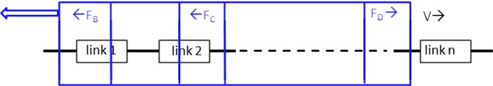
In previous works (round steel chains, roller chains), boundary conditions were added at the ends or fixed points at the chain [4, 5]. Since the chain runs through a conveyor layout (and thus the boundary conditions), a new modeling approach was chosen in which the chain is stationary and a boundary condition box passes through the chain links (see Fig. 3). As a result, a chain link is subjected to the different load ranges as it also occurs in the conveyor system. The boundary condition box is given by the conveyor layout and its forces (drive force , optional braking force , forces in curves ). The drive force is affected by the so-called polygon effect which results in an oscillating longitudinal force in the chain due to periodically changing pitch diameter during the rotation of the driven chain wheel. While passing chain links, the boundary conditions are assigned to the corresponding chain link by an additional algorithm in the simulation model. As result the tractive force , the acceleration and the speed are calculated for each chain link.
Fig. 2Chain link in the multi-body simulation model
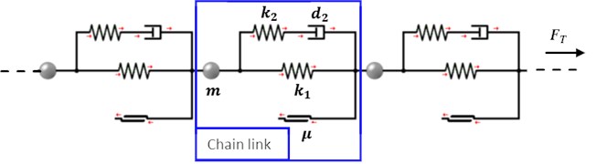
Fig. 3Boundary conditions passes the chain links
For dynamic simulation of components made of non-metallic materials, more exact damping approaches are recommended [6]. These consider internal damping forces due to the material deformation. Until now, no damping characteristics are known for sliding chains made of plastic. Therefore, hysteresis tests were carried out on a chain consisting of three chain links with different deformation rates and different maximum forces. It was found that the material behavior of the chain depends on deformation speed and tensile force in the chain. Therefore, the ZenerM model was chosen which consists of two springs and one damper [7]. This material model implicitly considers the deformation speed. The equation of viscoelastic force based on ZenerM ends in:
with as deformation path. To include the force dependency, one of the two springs and the damper are provided with an additional parameter. Finally, the material model features five parameters ( to ) to characterize the viscoelastic material behavior:
is the tensile force of the testing machine. The parameters were obtained through all recorded hysteresis curves by an optimization calculation. For the studied sliding chain type, these parameters are listed in Table 1.
Table 1Determined parameters for the viscoelastic material model of the sliding chain
[N/mm] | [N/mm] | [Ns/mm] | [1/mm] | [s/mm] |
1150 | 450 | 0,9 | 1,7 | 4,5 |
The viscoelastic force incorporated into the equation of motion of the simulation model besides the frictional force, the inertial force and the contact forces to adjacent chain links. With this equation of motion, the curves of tractive force, acceleration and speed are calculated, from which the vibrations will be determined.
3. Validation of the simulation model
The simulation model was validated on a test conveyor system based on an U-layout with a conveying length of 9 m (see Fig. 4). Test runs were done with conveying speeds from 0,04 to 0,3 m/s, loads of masses from 10 to 50 kg distributed over the conveyor length and two different slide rails. The coefficient of friction between sliding chain and each slide rail was determined in the system before: It was found that the speed-dependent coefficient of friction of both rails have an opposite characteristic. One slide rail showed a coefficient of friction increasing with speed, while the other showed a falling coefficient of friction. Furthermore, it was observed that the conveyor chain oscillates particularly strongly in certain friction pairings.
During a test run the acceleration of one chain link was recorded. For adjusting the model, an FFT of measurement data and the associated simulation data was performed and verified. The validation took place in the stationary state.
Fig. 4a) Test conveyor (clipped), b) layout
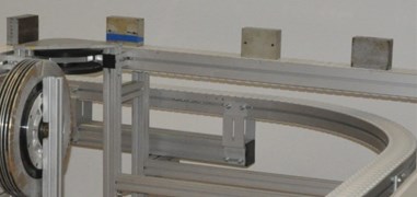
a)
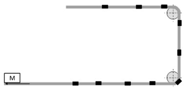
b)
4. Variant calculation and its results
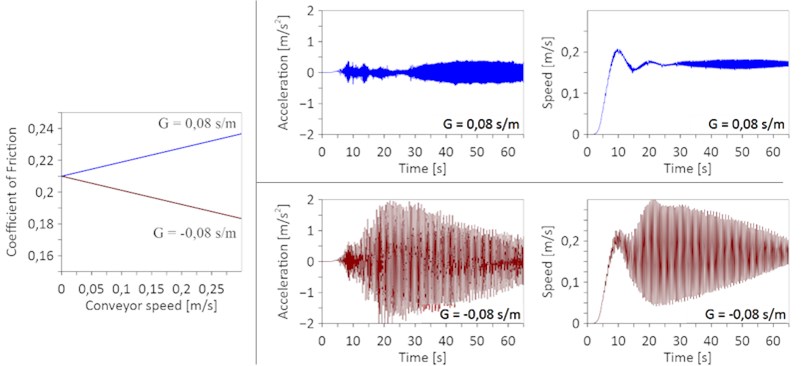
The influences of relevant parameters were investigated in the model with the help of a variant calculation. Due to the two coefficients of friction characteristics, positive and negative friction gradients have been studied. This article exemplifies a positive and negative gradient, which is shown in Fig. 5. Fig. 5 shows also the calculated acceleration and velocity curves for the two friction gradients. The time range of 20 to 60 s corresponds to a passage of a chain link including load in the chain way. The transient oscillation in first 20 s omits in stationary operation and was not investigated experimentally. With a positive gradient, the two curves reveal small deviations, so that the speed remains nearly constant after running-in. With a negative gradient, both curves show large deviations, which are rising to a maximum soon after running-in and then slowly decrease. The behavior could be proven experimentally.
Fig. 5Coefficient of friction as a function of speed (left, G is the friction gradient). Trend of simulated acceleration and speed for both coefficients of friction curves (right)
The meshing frequency which depends on conveying speed has been varied to obtain the maximum acceleration amplitude for each. For a test conveyor configuration used to generate Fig. 6, multiple peaks of acceleration amplitudes are obtained. These natural frequencies of the chain were also detected experimentally. In practice, these frequencies should be avoided.
Fig. 6Simulated maximum of acceleration amplitudes over meshing frequency
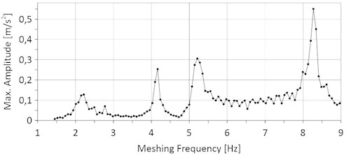
Fig. 7Maximum amplitudes at resonance for different numbers of teeth
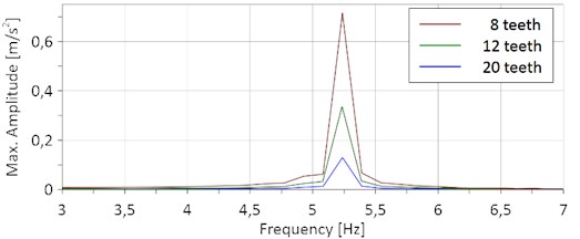
The number of teeth of the driven chain wheel has been examined and the maximum amplitude at resonance has been calculated. As in Fig. 7 shown, the resonance amplitude decreases with the number of teeth significantly. This is already known from the literature. The smallest chain wheel of the selected conveyor system should generally be avoided.
Other important parameters are the chain length, the loading of goods and the chain stiffness. They have an influence on the natural frequency as well. For further reading the studies are presented in [8].
5. Conclusions
Causes leading to vibrations in sliding chain conveyors were investigated experimentally and by simulations. For this purpose, a simulation model with rheological base elements has been created, which considers viscoelastic properties of the sliding chain. Since a chain runs through a conveyor system, a new modeling approach was chosen in which the chain is stationary and boundary conditions passes through the chain links. For validation and studying influences on vibrations, a conveyor layout was chosen and built.
The results of all experimental tests and subsequent simulations can be summarized: (1) Material characteristics of chains made of plastic are dependent on tensile force and deformation rate. (2) The coefficient of friction does not have a constant characteristic; it depends on load (weight) and conveying speed. (3) Viscoelastic properties of a plastic chain can be well approximated with the ZenerM element. (4) The two main sources of vibrational excitation are speed fluctuations due to the polygon effect on the driven chain wheel und friction induced vibrations. (5) Vibration amplitudes increase in the investigated range with conveying speed. (6) The magnitude of vibration amplitudes increases with a coefficient of friction falling with increasing speed. (7) In case of resonance, the magnitude of vibration amplitudes is influenced by number of teeth on the driven chain wheel (high amplitudes with low number of teeth).
Hence the following recommendations can be derived: (1) The vibrational excitation by the drive can be reduced by making sure that natural frequencies of the chain and the meshing frequency differ. (2) A drive unit with a chain wheel with a high number of teeth should be installed in the conveyor system. (3) Friction pairings between sliding chain and slide rail should be carefully selected. It is not only important to look after a low discrete coefficient of friction, but also to consider the complete friction characteristic and to choose a characteristic with a slightly increasing coefficient friction with increasing conveying speed.
References
-
Mitschke F. Eigenschaftsprofile neuartiger faserverstärkter Kunststoffgleitketten für den Stückguttransport. Dissertation, TU Chemnitz, 2008.
-
Auerbach P. Zur Beanspruchung und Lebensdauer raumgängiger Gleitketten aus Kunststoff. Dissertation, TU Chemnitz, 2006, http://nbn-resolving.de/urn:nbn:de:swb:ch1-200600396.
-
Sumpf J., Bankwitz H., Nendel K., Rasch F. Novel calculation method for chain conveyor systems. Logistics Journal: referierte Veröffentlichungen, Vol. 2014, Issue 11, 2014, https://doi.org/10.2195/lj_Rev_sumpf_en_201411_01.
-
Fritz P. Dynamik schnelllaufender Kettentriebe. VDI Fortschrittsberichte, Vol. 11, No. 253. VDI Verlag, Düsseldorf, 1998.
-
Ziegler M. Die Beanspruchung mechanischer Komponenten endloser Kettentriebe in der Kohle-gewinnung durch eigen- und fremderregte Schwingungen. Ph.D. Thesis, Ruhr-Universität Bochum, 2006
-
Dresig H., Fidlin A. Schwingungen Mechanischer Antriebssysteme. 3rd ed., Springer Vieweg, Berlin Heidelberg, 2014, https://doi.org/10.1007/978-3-642-24117-8.
-
Nasdala L. FEM-Formelsammlung Statik und Dynamik. Vieweg+Teubner Verlag, 2010, https://doi.org/10.1007/978-3-8348-9922-4.
-
Strobel J. Untersuchung von Schwingungen an einem Stetigfördersystem mit Kunststoffgleitketten. Ph.D. Thesis, TU Chemnitz, 2018, http://nbn-resolving.de/urn:nbn:de:bsz:ch1-qucosa2-211447.
About this article

