Abstract
This paper aims to provide a slope stability analysis for the southern part of Wuchangping mine. The methods of limit equilibrium analysis, finite element simulation and neural network were used to study the stability of the southern slope. The preventive measures, such as bolt reinforcement, drainage system and so on were carried out. The results are as follows. The slope angle for the lower slope of moderately weathered granite and slightly weathered granite is recommended as 60°-65°. The slope angle for the layer where locates near the ground of full weathered granite is recommended as 30°-32°. When the thickness of fully weathered granite layer is less than 10 meters, the slope is still stable enough. The angle is recommended as 38°-40°. The results of evaluation and calculation obtained by the neural network are not different from those of the limit equilibrium method and finite element simulation. The neural network can accurately predict slope stability. The conclusions can provide useful reference for similar mines.
Highlights
- Several geotechnical analysis methods was utilized to determine and describe properties of rock mass.
- Three methods, i. e. neural network, limit equilibrium method and numerical simulation, are used to study slope stability.
- Through a series of studies, the unstable region of slope is obtained.
- The targeted solution is provided in the manuscript.
1. Introduction
Stability of an open pit slope has always been an important research topic. The slope of an open pit mine will collapse or slide. At present, scholars have carried out a series of research work on slope stability of the open pit stope.
S. S. Rathore et al. [1] carried out geotechnical engineering research on the proposed open pit lignite mine and designed safety slope with high wall steps. A. Ozbay and A. F. Cabalar [2] carried out a series of numerical analyses by using the finite element method and the limit equilibrium method to evaluate factors that caused the landslides. A. B. N. Dassanayake [3] studied the groundwater pressure effect and slope stability analysis of C1 pit on deep pit mining of Mae Moh open pit lignite mine, Thailand. Groundwater flow model was constructed and run using Visual Modflow 3D. Wang et al. [4] studied the measuring system of three-dimensional displacement field and monitored the soil displacement change of a slope. A. Kainthola et al. [5] studied a case of a failed dump slope in western coalfield limited, Nagpur, India. A huge mass of debris flow had happened during the routine of the activity of mining. Levent Tutluoglu et al. [6] presented the results of slope stability analysis via finite difference code and a limited quilibrium software for the soil slopes of the Elbistan-Collolar lignite mine. Z. Bednarczyk [7] performed slope stability studies and geotechnical analyses within a project conducted by Poltegor-Institute. The calculation procedure enabled determination of slope stability on the design of excavation and spoil dump. Viroon Kamchoom et al. [8] established a finite element seepage stability model and verified the rainfall instability of 45 degree viscous sand slope under heavy rainfall by centrifugal model test. Ezra Stockton et al. [9] proposed an improved logarithmic spiral limit equilibrium method to determine the critical failure mechanism and stability of slope under the condition that both friction angle and cohesion show anisotropic shear strength. Zheng et al. [10] adopted limit equilibrium method and parallel layer model (PLM) to study the effect of the and the on slope stability. Results show that the selection of in the slope model plays an important role in the calculation of FOS. The expansive soil has a significant effect on the stability of a slope. The strength of jute fiber reinforced expansive soil has been studied [11-15]. Through the above research results, many scholars have carried out relevant research work.
Based on specific engineering examples, several geotechnical analysis methods include RMR (Bieniawski’ RMR), Q-system (Barton’s Q-system), MRMR (Laubscher’s Mining Rock Mass Rating), GSI (Modified Hoek-Brown Failure Criterion and Geological Strength Index), RES (Hudson’s Rock Engineering Systems), was utilized to determine and describe properties of rock mass. Bieniawski’ RMR adopted five grading parameters, such as rock strength, rock quality index (RQD), joint spacing, joint state, and groundwater condition. The basic principle of GSI is that in the evaluation of rock mass strength index, the most basic parameter is the evaluation or measurement of uniaxial compressive strength () and material constants () related to rock friction characteristics. The numerical technique, such as the finite element method (FEM) is also used to find approximate solutions to boundary value problems. The results can provide reference for similar projects.
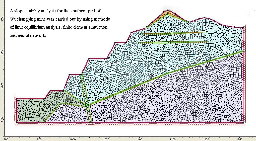
2. The basic overview of current slopes
2.1. The general situation of slope
Wuchangping tin mine is an open pit mine located about 50 km south-west of Chenzhou in Hunan province. The life of mine is estimated to be around 11 years according to previous feasibility reports. There exists a layer of granite weathering crust in the slope of the eastern pit. The estimation of weathering degree to drill core samples has shown that entire deposit can be divided into heavily weathered layer, moderately weathered layer, and slightly weathered layer respectively as it goes deeper. Granite which formed inside heavily weathered layer contributes to a granular structured layer. However, once the surface is excavated, this loose and heavily weathered granite is very likely to “collapse” (especially with mass rainfall). All these geological factors influence the mine operation. The purpose of the research is to determine a reasonable slope angle that could minimize the cost and ensure safe production.
2.2. Pre-designed parameters of the slope
The major parameters designed by Changsha Institute of Mining Research are summarized followed.
1) Bench height is 12 meters.
2) Do not merge benches between heavily weathered granite layer and soil layer.
3) Bench angle is 45°-75°.
4) Bench width is 12 m-21 m. The minimum bench width is 3 m without merging.
5) Overall slope angle is 34°-46°.
6) Maximum height of the slope is 204 m.
2.3. Lithology of slope
Lithology of the slope from the surface to deep mine are listed below.
1) Silty clay: it contains quartz gravel and a little plant rhizomes, the thickness of these strata is around 1.5 m-8.9 m.
2) Fine grained granite (full-strong weathered layer): all components were weathered expect quartz. Thus, feldspar and mica were transformed to clay. The thickness of these strata is around 8 m-92.50 m. The average thickness is 39.73 m.
3) Fine grained granite (moderately weathered layer): the degree of weathering for this strata is comparably low. The weathering process only take place in the crack near the surface. Therefore, rock inside this strata is fine. The thickness is 1.5 m-5 m.
4) Fine grained granite (slightly weathered layer): There are no cracks or cracking factors, almost no weathering phenomenon, and the rock is absolutely delicate.
2.4. Hydrogeological conditions
Current slope hydrogeology condition is simple. Groundwater is mainly consisted of fissure water that leakage from fine grained granite layer. The water yield property of this mine is comparably weak. The water source is mainly from atmospheric precipitation. The ore is at the depth of around 27 m-52.10 m. Runoff discharge conditions are good. Influenced by topography, the runoff is transverse from east to west. In the middle of the terrain, low-lying wetlands or springs emerge from the surface and are seasonally adjusted.
2.5. Site seismic effect
Vibration level of the mine is 4 minuses. Intensity is about 6 degree. Peak ground acceleration is 0.05 g (equivalent to the seismic intensity of VI class). Period of ground motion response is 0.35 s. Some scholars have studied the dynamic stability of slope. The influence of seismic peak value on slope stability is discussed [16-18].
2.6. Numerical analysis of structure plane occurrence
According to the statistical results of surveying and mapping for the mine site, it is possible to draw structure planes for moderately weathered granite and slightly weathered granite through numerical analysis software called Dips. The results are displayed in Table 1.
Table 1Main joint plane occurrence
Rock types | Main joint plane occurrence | ||
1 | 2 | 3 | |
Moderately weathered granite | 329°∠81° | 72°∠76° | 133°∠63° |
Slightly weathered granite | 142°∠81° | 73°∠88° | – |
Through stereographic projection for analyzing main structural planes and slope direction, structural plane has less effect on slope stability. Therefore, the slope is stable.
2.7. The physical and mechanical parameters of rock and soil
The geotechnical analysis methods, such as RMR, Q-system, GSI, and so on, were used to analyse the rock mass quality. The experimental results are reduced by 85 % as the real mechanical parameters. Selected parameters of rock mass were shown in Table 2.
Table 2The mechanical parameters of rock masses and soil
No. | Rock types | Density / (g/cm3) | Cohesion / (kPa) | Angle of internal friction / (°) | Elastic modulus / (MPa) | Poisson ratio | Uniaxial tensile strength / (MPa) |
1 | Colluvial soil | 2.2 | 15 | 20 | 100 | 0.35 | 0 |
2 | Heavily weathered granite | 2.0 | 50 | 24 | 800 | 0.30 | 0 |
3 | Moderately weathered granite | 2.60 | 800 | 30 | 2066 | 0.14 | 1.5 |
4 | Slightly weathered granite | 2.66 | 1300 | 38 | 9976 | 0.13 | 2.6 |
3. Limit equilibrium analysis of slope
The traditional limit equilibrium method shows that the slope is prone to slide under the action of gravity. This analysis provides a factor of safety, defined as a ratio of available shear resistance (capacity) to that required for equilibrium. Hence the program analyses the stability of generally layered soil slopes, mainly embankments, earth cuts and anchored sheeting structures. Limit equilibrium methods include Morgenstern-Price, General limit equilibrium, Spencer, Bishop, Fellenius, Ordinary, Janbu etc. [19-22].
3.1. Theory of limit equilibrium analysis
The limit equilibrium method adopted Fellenius method, simplified Bishop method, Janbu simplified method and Spencer method. The shape of the potential slip surface in Wuchangping tin mine is mainly considered.
(1) Fellenius method.
The basic assumptions of the Fellenius method are as follows: The sliding surface is assumed to be an angular arc. The interaction force between slices is not considered in the calculation. The resultant force direction between the two sides of the strip is parallel to the base surface. The stability safety factor of sliding arc can be obtained by the following Eq. (1):
where is the cohesive force of block No.i. is the internal friction angle of block No.i. is the weight of block No.i and the weight of overlying tailings. is the bottom edge length of block No.i. is the horizontal force acting on block No.i. is the angle between the bottom edge of block No.i and the horizontal plane of coordinate axis. is the horizontal force acting on block No.i.
(2) Bishop method.
It assumes that the force between slices keeps the horizontal direction. The horizontal thrust force is assumed. The vertical shear force between slices is not taken into account. The stability safety factor of the circular slip surface can be obtained by the following Eq. (2):
Since both sides of Eq. (2) contain , it requires an iterative calculation to obtain more accurate results. A large number of calculation examples show that the Bishop method is close to other accurate calculation results. The parameters in Eq. (2) are consistent with those in Eq. (1).
(3) Janbu method.
Janbu method has the following basic assumptions. The critical slip surface shape is any curve. The stability safety factor of the whole sliding surface is the same. Based on the above assumptions, the formula for calculating the safety factor of slope stability by Janbu method can be obtained:
where is shear force on the side of block No.i. is normal force on the side of block No.i. is width of block No.i. is normal force on the bottom edge of block No.i. is shear force on the bottom edge of block No.i. Initial conditions are 0, 0.
(4) Spencer method.
Spencer method assumes that the resultant force between blocks is fixed at the angle in the horizontal direction. Therefore, the direction of the resultant forces among the blocks is parallel to each other. The sliding surface is arbitrary curve. If the force is balanced in the direction perpendicular to and parallel to the bottom of the strip, there are two formulas as follows:
where is normal resultant force from bottom to top of the strip. is tangential force on the bottom of the strip. is weight of block; is horizontal force. is slip angle.
According to the Mohr-Coulomb criterion, the following relations can be obtained:
where , /. is a safety factor. In the limit equilibrium method, safety factor can be understood as strength reduction factor of rock mass under limit equilibrium condition. Namely, . Thus, the difference of resultant forces between the two sides of a strip can be obtained:
Because 0 in the limit equilibrium state, the following formula can be obtained:
In addition, the moment balance condition that the sliding body must satisfy the following formula:
where is distance from the center of rotation at the bottom of each block. If the sliding surface is a circular arc, the upper formula can be written as the following:
By substituting Eq. (11) for Eq. (12)-(14), the safety factor can be obtained.
3.2. Determine the slope sliding mode and sliding surface
Slope stability is affected by the components, structure, and environments. The main basis for judging failure mode of a slope is to identify the correlated relationship between rock mass structure and slope.
There exists three assured sliding surface on the slope of eastern Wuchangping tin mine.
(1) Sliding surface of silty clay layer and the full or heavily weathered fine-grained granite developed along the slope where relief under the steep. It is possible to form a small scale collapsing in the big storm season.
(2) Sliding surface of heavily weathered fine grained granite and moderately weathered fine-grained granite also developed along the slope where the slope angle varies from 30° to 35°. It is highly possible to form mud-rock flow, land sliding and large collapsing when the big storm season comes.
(3) Sliding surface between fracture zone, footwall and hanging wall rocks, are mainly formatted in full or heavily weathered fine-grained granite layer, the dip direction of fracture zone is in the same as the surface, extremely possible to from a sliding or collapsing.
Past experimental evidence has shown that the landslide slip surface can be approximately expressed as vertical fracture of the anterior arch. It was generally treated as arc failure mode when joints in slopes were up to 3-4 groups. Normally, there are around three groups of structure planes inside moderately weathered granite and slightly weathered granite in Wuchangping tin mine. There exists some mine-out stopes in the mine and several of them are located just at the bottom of the slope, but all of these stopes are quite small. Therefore, it has less impact on slope stability. So that the mine-out area is not a factor that affecting slope stability.
3.3. Factor of safety
FoS is a constant value imposed by law, standard, specification, contract or custom to which a structure must conform or exceed. Factor of safety is significant in evaluating slope stability. After fully considering about geotechnics, hydrogeological, and life of the mine, the allowance factor of safety has been determined [] to be:
Normal: 1.15, Seismic: 1.05.
If estimated factor of safety for slope , then the slope is absolutely stable; if 1 , the slope is usually stable, when 1, the slope is unstable.
3.4. Conditions when analyzing strength
There are three conditions when we are dealing with load strength analyzing:
(1) With gravity but no rains and no seism,
(2) With gravity and seism but no rains,
(3) With gravity and rains but no seism.
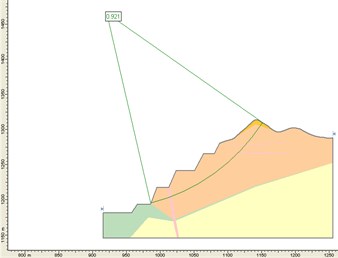
3.5. Results and conclusions
Through stereonet analysis for section 70, 74, 75, 76 and 78 on eastern Wuchangping tin mine and the additional section 80, A-A, B-B, and C-C required by Yunxi Consultancy Ltd., several geotechnical results have been calculated and shown in Table 3.
The potential sliding plane, which intersects with slightly weathered granite layer, usually has a safety factor that greater than 1.5. Thereby, it is stable enough without any sliding and collapsing.
Upper slope of 9 sections, selected by Changsha non-ferrous design Ltd, Wuchangping tin mine, Yunxi Consultancy Ltd. and CIMR, has a safety factor that less than 1.15, which means it is really unstable and potential to slide in silty clay layer.
Seismic effects lead to factor of safety reduction of 2.9 % to 10.1 %. Another FoS decrease of 14.4 % to 25 % is due to rains. It has significant impact on stop stability rather than seism. Therefore, rain is the most significant factor when engineers are preventing the deposit from sliding disasters. Groundwater mainly comes from rainfall in eastern mine and the topography near the section 76, 78 benefits of groundwater drainage. So, it does not have impact on the slope stability as pre-estimated from calculations.
The slope angle is in the lower part of weathered granite was determined to be 60°-65°. Based on the analysis of stope stability of C-C section, slope angle of limestone can be increased to 60°-65°.
Table 3The safety factor of potential slide surface in the 78 section
No. | Analysis objects | Potential sliding surface (height / m) | Condition | Factor of safety | |||
Fellenius | Bishop | Janbu | Spencer | ||||
1 | Allowance factor of safety | 648→765 | Ⅰ | 0.889 | 0.921 | 0.880 | 0.915 |
2 | Preliminary designed overall slope | 636→753 | Ⅰ | 1.456 | 1.543 | 1.396 | 1.561 |
3 | When slope angle is 30° | 648→752 | Ⅰ | 1.100 | 1.154 | 1.088 | 1.150 |
4 | When slope angle is 38° | 648→764 | Ⅰ | 0.850 | 0.896 | 0.841 | 0.890 |
5 | When upper slope angle is 42° | 648→765 | Ⅰ | 0.850 | 0.882 | 0.842 | 0.879 |
6 | When upper slope angle is 42° with seismic effects | 648→765 | Ⅱ | 0.808 | 0.839 | 0.799 | 0.835 |
7 | Pre-designed FoS before construction | 648→756 | Ⅰ | 1.008 | 1.049 | 0.996 | 1.046 |
8 | Overall FoS before construction | 636→757 | Ⅰ | 1.543 | 1.619 | 1.489 | 1.635 |
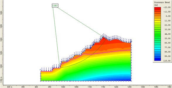
9 | FoS for upper slope with rains before construction | 648→770 | Ⅲ | 0.791 | 0.851 | 0.794 | 0.851 |
10 | Pre-designed FoS by Yunxi Consultancy Ltd. | 756→761 | Ⅰ | 1.192 | 1.185 | 1.173 | 1.188 |
11 | Adjusted FoS by CIMR | 672→766 | Ⅰ | 0.969 | 1.007 | 0.953 | 1.003 |
According to the preliminary design by CIMR, full weathered granite which locates in the upper part of the slope, is stable enough when the slope angle is not steep than 30°-32°, especially for the section 78. However, when the full weathered granite thickness is less than 10 m, the stable slope angle could jump to 38°-40°.
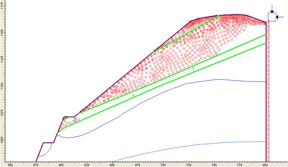
Fig. 1The minimum factor of safety of the potential sliding surface in section 78
Pre-designed slope disability of construction drawing varies where the heavily weathered granite distributed from different thickness. The unstable section is still in the upper part of heavily weathered granite layer, especially for interface between heavily weathered granite and moderately weathered granite. This interface is the main sliding surface that must be reinforced by planting bolts or other reinforcement measures.
The slope surface protection area on the north open pit is section 70-74. The sections of 75 and 76 A-A are the focused reinforcing area. In southern open pit mining, the unstable area near B-B section should be reinforced reliably.
Fig. 2The pre-designed safety factor of potential sliding surface from construction drawings in section 78 considering with rain
4. Finite element simulation of slope
In order to analyze the stability of the slope and estimate the limit equilibrium conditions, it is necessary to conduct a comprehensive finite element simulation of the slope. A Canadian finite element computing package called Phase 2 has been used in this research. Phase2 is a powerful 2D elasto-plastic finite element stress analysis program for underground or surface excavations in rock or soil [23-27]. It can be used for a wide range of engineering projects and includes support design, finite element slope stability, groundwater seepage and probabilistic analysis.
4.1. Principle of finite element analysis
According to the physical approximation, the finite element method divides the continuum into a finite number of elements, which are articulated at the nodes to form a discrete structure. These discrete structures are used to replace the original continuum structure. When the compatibility conditions of deformation between adjacent elements, the equilibrium conditions of forces acting on the elements, and the displacement of each element corresponding to the mechanical properties of the element materials (stress-strain relationship) are satisfied, the loads are displaced to the nodes of the discrete structures and become the nodal loads. The stress-strain relationship is as follows:
where, is element stress, is elastic matrix, is element strain.
Based on the principle of virtual displacement and the relationship between stress and strain, the relationship between node load and node displacement can be established. That is, node equilibrium equations expressed by displacement:
where, is stiffness matrix, is node displacement array, is nodal load array, is element elastic matrix, is element strain matrix.
The basic idea of the finite element method is that the displacement field can be obtained by solving the Eq. (18), and then the distribution of strain and stress can be derived. It is actually a numerical solution of a differential equation.
According to rock characteristics of Wuchangping tin deposit, the Mohr-Coulomb yield criterion is adopted in this study. Its expression is as follows:
where, is internal friction angle, is cohesive force:
The elastic-plastic stress-strain relationship of the whole medium is as follows:
where, is elastoplastic matrix:
where, is hardening coefficient, for ideal elastoplastic analysis, 0. is partial derivative vector of yield function to stress component. The yield function expressed by Eq. (19), can be expressed as following Eq. (22):
where, is effective stress, and , .
4.2. Numerical modeling
According to the engineering geological characteristics of east slope of Wuchangping tin mine and the current operational status, it is acceptable to treat section 76, 78 as the numerical modeling objects. The primary purpose of this modeling is to estimate the slope stability with different pre-designed slope angles.
The boundary condition of the model is described here to understand the geotechnical environment. Slope surface is a free surface, planes on both sides are fixed at horizontal direction, bottom is fixed at vertical direction. The original rock stress field is the self-weight stress field. The maximum tensile stress criterion and Mohr-Coulomb yield criterion are used to determine the possible stress field, displacement and shear failure zone of excavated slope.
4.3. Finite element analysis results of section 76
Simulation of this section has been conducted in two states, the preliminary design of slope (M1 model) and the upper slope was fixed at 38° (M2 model) (More modeling simulation will be given upon request).
Fig. 3The max primary stress (σ1) distribution of M1
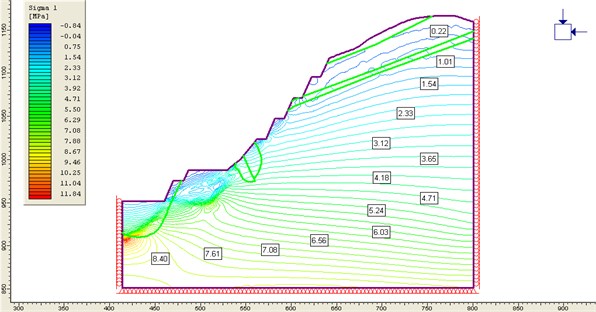
Fig. 4The tension and shear failure area of the M2
The internal stress of rock mass (as shown in Fig. 3) increases with the increase of depth. Close to the slope, the smaller the principal stress is. In the deeper part, the principal stress is in the vertical direction, and then gradually becomes the downward direction along the slope. The stress of the lower slope is affected by the mine steps, and the stress disturbance is relatively high. The stress values inside slope are moderate. It exists several small scale shear stress zones.
Displacement is moving towards to mine-out area. The upper slope of weathered granite has the maximum displacement as well as a clay layer. The main reason for this it’s all rock inside the area has a low strength. When the slope becomes smaller, the displacement will decrease.
The tension shear failure zone (shown in Fig. 4) of the slope is mainly distributed in the clay zone and weathered granite layer. The tensile failure zone locates beneath the earth around 12 m-17 m.
4.4. Finite element analysis results of section 78
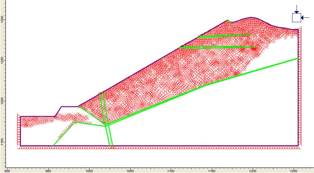
Simulation of this section has been conducted in three states, the preliminary design of slope (N1 model), the upper slope was fixed to 30° (N2 model) and the upper slope was fixed to 38° (N3 model).
The simulation and analysis results of section 78 are similar to section 76 above. The differences between sections 78 and 76 are as follows.
In this section of the heavily weathered granite is distributed throughout the slope and occupied the major area. The tensile shear failure zone for this section is the largest among the mine (shown in Fig. 5). They mainly locate inside the diluvial clay layer, heavily weathered granite layer and the bottom of the slope in moderately weathered granite. Tensile failure zone is located in the outer slope, range from 20 to 35 m. There exists a small range of shear stress zone at the bottom of the slope.
Displacement (shown in Fig. 6) occurred mainly in the diluvial clay layer and heavily weathered granite layer. Value of displacement is comparatively high. When the slope becomes smaller, the displacement will decrease.
Fig. 5The displacement distribution of the N1
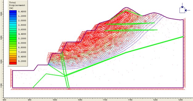
Fig. 6Tension and shear failure area of the N2
5. Evaluation of slope stability by neural network
Neural network has been applied in many fields with its special functions of self-learning, self-organization, associative memory and parallel processing. It can realize highly non-linear mapping without knowing the relationship between data distribution and variables. It is suitable for extracting knowledge from examples and acquiring knowledge. It is an effective method to solve the “bottleneck” problem of knowledge acquisition.
Therefore, this study uses the visual fast neural network model based on MATLAB to compile the neural network software, greatly simplifies the programming work, improves the convergence speed of the network, shortens the training time, and applies the network to slope stability evaluation with high degree of visualization and good evaluation effect.
5.1. Design of visual fast neural network
(1) MATLAB neural network toolbox.
Neural network toolbox is one of many toolboxes developed under the environment of MATLAB. Based on the theory of artificial neural network, it constructs activation functions of typical neural networks with MATLAB language, such as s-type, linear, competitive layer, saturated linear and so on. It makes the designer's calculation of the output of the selected network to become the call of activation functions. In addition, according to various typical rules of modifying network weights and the training process of network, various subprograms of network design and training are compiled with MATLAB.
(2) A fast-neural network algorithms-elastic BP network model.
There are two kinds of fast algorithms for neural networks. One is heuristic learning algorithm developed from standard steepest descent optimization algorithm. The other is improved heuristic learning algorithm, including the momentum method, variable learning rate BP algorithm and elastic BP algorithm. Through the practical checking calculation of slope stability analysis and evaluation. It is considered that the elastic BP algorithm is better than other methods in terms of calculation time and accuracy.
The transfer function of the hidden layer of the conventional multi-layer network is s-type. The s-type function has the characteristic of transforming the infinite input range into the limited output range, and the slope of the function approaches zero when the input number is large. Thus, when the steepest descent method is used to train the multi-layer network composed of s-type functions, a problem will arise, that is, when the gradient may have only one very small gradient. When the value is zero, the variation of weight and deviations is very small, even if the weight and deviations are far from the optimal value.
Elastic BP training algorithm can eliminate these harmful effects on the size of partial derivatives. Only the symbols of derivatives are used to determine the direction of weight updating. The size of derivatives has no effect on weight updating. The size of weight changes depends on an independent correction value. The updating value of each step’s weight and deviation increases with the incremental factor when the performance function of the derivative and the corresponding weight have the same symbols in two continuous cycles, decreases with the decreasing factor when the derivative and the corresponding weight change symbols in the previous cycle, and keeps the updating value unchanged when the derivative is zero. When the weight oscillates, the change of the weight decreases. If the weight changes continuously along the same direction after several cycles, the change of the weight increases. The complete description of the elastic BP training algorithm is referred to the literature.
5.2. Neural network estimation of slope failure and stable examples
(1) Case collection.
Seventy-two examples of slopes with arc sliding potential or sliding failure modes in various mines and geotechnical engineering are collected and sorted out from relevant literature at home and abroad (36 of them are failure cases and 36 of them are stable cases).
(2) Neural network estimation of slope stability for potential arc failure.
Seventy-two samples were input into the trained neural network (Table 4 is a partial sample). The network structure of 6-56-2 is adopted. There are six neurons in the input layer, which represent six factors affecting slope stability: rock bulk density, cohesion, internal friction angle, slope angle, slope height and pore pressure ratio. There are 56 neurons in the hidden layer. The hyperbolic tangent s-type transfer function is adopted. There are two neurons in the output layer. Linear transfer function is used. It corresponds to the estimated safety factor and the stable state of the slope, respectively. Descriptive information of stable state: stability and destruction is represented by digital codes 1 and 0. 72 samples are provided for network learning, and the network converges after 1680 iterations.
Table 4Examples of stability or failure of potential circular sliding of slopes
Number | Bulk density (kN/m3) | Cohesion (kPa) | Internal friction angle (°) | Slope angle (°) | Slope height (m) | Pore pressure ratio | FoS | Slope condition |
1 | 31.3 | 68 | 37 | 47 | 213 | 0.25 | 1.20 | Destruction |
2 | 25.0 | 55 | 36 | 45.5 | 299 | 0.25 | 1.52 | Stability |
3 | 31.3 | 68.6 | 37 | 47 | 305 | 0.25 | 1.20 | Destruction |
4 | 25.0 | 48 | 40 | 49 | 330 | 0.25 | 1.49 | Stability |
5 | 25.0 | 46 | 35 | 46 | 393 | 0.25 | 1.31 | Stability |
6 | 27.3 | 10 | 39 | 40 | 480 | 0.25 | 1.45 | Stability |
7 | 21.43 | 0 | 20 | 20 | 61.0 | 0.5 | 1.03 | Destruction |
8 | 18.84 | 0 | 20 | 20 | 7.62 | 0.45 | 1.05 | Destruction |
9 | 18.84 | 15.32 | 30 | 25 | 10.67 | 0.38 | 1.63 | Stability |
10 | 20.41 | 33.52 | 11 | 16 | 45.72 | 0.2 | 1.28 | Destruction |
11 | 23.47 | 0 | 32 | 37 | 214.0 | / | 1.08 | Destruction |
12 | 12.0 | 0 | 30 | 35 | 4.0 | / | 1.44 | Stability |
13 | 21.4 | 10.0 | 30.34 | 30 | 20.0 | / | 1.70 | Stability |
14 | 20.60 | 16.28 | 26.5 | 30 | 40 | / | 1.25 | Destruction |
15 | 28.44 | 29.42 | 35 | 35 | 100 | / | 1.78 | Stability |
Table 5Comparison of the actual state of slope with the results of neural network calculation
Number | Actual state of slope | Output of neural network | ||
FoS | Status code | Safety factor estimates | State prediction | |
1 | 1.20 | 0 | 1.2151 | 0 |
2 | 1.52 | 1 | 1.5401 | 1 |
3 | 1.20 | 0 | 1.2194 | 0 |
4 | 1.49 | 1 | 1.4582 | 1 |
5 | 1.31 | 1 | 1.2933 | 1 |
6 | 1.45 | 1 | 1.4490 | 1 |
7 | 1.03 | 0 | 1.0127 | 0 |
8 | 1.05 | 0 | 1.0453 | 0 |
9 | 1.63 | 1 | 1.6153 | 1 |
10 | 1.28 | 0 | 1.2785 | 0 |
11 | 1.08 | 0 | 1.0715 | 0 |
12 | 1.44 | 1 | 1.4497 | 1 |
13 | 1.70 | 1 | 1.6984 | 1 |
14 | 1.25 | 0 | 1.2885 | 0 |
15 | 1.78 | 1 | 1.7294 | 1 |
The results of some training samples are shown in Table 5. From the comparison results, it can be seen that the neural network can make an accurate judgment of the slope stability and failure state. The safety factor is estimated accurately. In order to verify the applicability of the model, four engineering examples which were not trained were selected as test samples for the calculation. The test results are shown in Table 6. It can be seen from the table that the neural network can accurately estimate the safety factor and failure state of the slope and can be used in the stability analysis of the slope.
Table 6The actual state of the test samples and the evaluation of the neural network
Number | Bulk density (kN/m3) | Cohesion (kPa) | Internal friction angle (°) | Slope angle (°) | Slope height (m) | Actual status | Network output | ||
FoS | Condition | FoS | Condition | ||||||
1 | 18.4 | 15 | 18 | 26.6 | 20 | 1.5 | Stability | 1.57 | Stability |
2 | 23 | 1.6 | 35 | 56 | 163 | 1.1 | Destruction | 0.73 | Destruction |
3 | 23.3 | 11 | 20 | 40.5 | 144 | 1.07 | Destruction | 1.09 | Destruction |
4 | 26.5 | 20 | 20 | 42 | 96 | 0.79 | Destruction | 0.77 | Destruction |
5.3. Stability evaluation of eastern slope
According to the stability analysis results of the eastern slope mentioned above, the stability of the eastern slope of Wuchangping tin mine mainly depends on the stability of the weathered granite shell on the surface of the slope, that is, the stability of the strongly weathered granite. From the stability analysis results of several profiles, it can be seen that the weathered granite on the slope of line 78 of Wuchangping tin mine has the thickest distribution and the worst stability. The 78 line is used as the analysis and evaluation section of the neural network.
According to 50 kPa, 24°, without considering the effect of water, the starting point of calculating slope height is 648 m step. The estimated values of slope safety factor based on neural network at different slope angles are shown in Table 7. The results of evaluation and calculation are not different from those of limit equilibrium method. The judgment of slope stability is unstable. The basic reason is that the rock stratum of strong weathered granite is thicker, the height of slope is higher and the mechanical strength of slope is not large.
Table 7Neural network for stability evaluation of eastern slope of Wuchangping tin mine
Number | Bulk density (kN/m3) | Cohesion (kPa) | Internal friction angle (°) | Slope angle (°) | Slope height (m) | FoS | Network Output |
1 | 20 | 50 | 24 | 28 | 105 | 1.14 | Destruction |
2 | 20 | 50 | 24 | 30 | 105 | 1.09 | Destruction |
3 | 20 | 50 | 24 | 32 | 110 | 1.03 | Destruction |
4 | 20 | 50 | 24 | 35 | 116 | 0.97 | Destruction |
5 | 20 | 50 | 24 | 38 | 118 | 0.95 | Destruction |
6 | 20 | 50 | 24 | 41 | 86 | 0.97 | Destruction |
7 | 20 | 50 | 24 | 42 | 83 | 0.97 | Destruction |
6. Slope treatment measures
According to lithology of slope and its stability analysis above, several treatment measures [28] were determined as follow.
6.1. Bolt system of reinforcement
Supporting range: in between 30 m north of section70 and 80 m south of section 50 m.
Bolt system: drilling depth is 2 m-33.7 m. Pore size is Φ 75. Dipping angle is 15°. Row spacing is 2 m. Column spacing is 1.50 m. Reinforced bar material is HPB335 common thread steel. Specifications type is 25 or 32. Bolt length is 20 cm.
Reinforcing mesh strengthen with HPB235 as well, the specification type is 8. Grid is 20 cm×20 cm. Reinforced joints should be welded.
Concrete jet is typed with C20. Thickness is around 10 cm. Perfusion mortar drill grade is M10.
Drain pipe type is 50PVC tube. Its length is 0.50 m. Insertion depth is 35 cm. The inserted pipe must be wrapped with a filter layer, prevent fine particles of strong weathered layer from leakage into groundwater. The drainage pipe is in the center of four adjacent bolts, layout density is the same as the bolting system.
6.2. Design drainage ditch
In order to prevent the infiltration of surface runoff into reinforcement, ensure stability of the slope, it is necessary to plant drainage ditches at top and bottom of reinforced slope. The design of drainage ditches is based on the maximum daily precipitation. Size of the drainage ditches on the top of reinforced slope is 1m (wide)×0.4 m (height), the bottom of it displays 0.4 m (wide)×0.4 m (height). Strength of cemented material should be C10. Thickness is no less than 5 cm.
7. Conclusions
Based on specific engineering examples, several geotechnical analysis methods include RMR (Bieniawski’ RMR), Q-system (Barton’s Q-system), MRMR (Laubscher’s Mining Rock Mass Rating), GSI (Modified Hoek-Brown Failure Criterion and Geological Strength Index), RES (Hudson’s Rock Engineering Systems), was utilized to determine and describe properties of rock mass. The Phase 2 software and neural network were used to carry out the research work. The following conclusions can be drawn.
1) According to lithology of slope, slope angle can be determined separately for those weathered layers. The slope angle in the lower part of the slope in moderately weathered granite layer and slightly weathered granite layer is better to be 60°-65°.
2) The slope angle for the layer where locates near the ground of full weathered granite, is general about 30°-32° to maintain stable. However, when the thickness of full weathered granite layer is less than 10m, slope is still stable enough while we increase the angle to 38°-40°.
3) The slope treatment area is in between 30 m north of section 70 and 80 m south of section 50 m, which needs a reinforcement combining with bolting system and some drainage ditches.
4) The results of evaluation and calculation obtained by neural network are not different from those of limit equilibrium method and finite element simulation. The judgment of slope stability is unstable.
References
-
Rathore S. S., Jain S. C., Bhardwaj G. S. Safe mine slope stability analysis for a opencast lignite mine – a case study. The Indian Mining and Engineering Journal, Vol. 53, Issue 9, 2014, p. 8-12.
-
Ozbay A., Cabalar A. F. FEM and LEM stability analyses of the fatal landslides at Çöllolar open-cast lignite mine in Elbistan, Turkey. Landslides, Vol. 12, Issue 1, 2015, p. 155-163.
-
Dassanayake A. B. N., Phien-Wej N., Giao P. H. Groundwater flow modeling and slope stability analysis for deepening of Mae Moh open pit lignite min. Geotechnical Engineering Journal of the SEAGS and AGSSEA, Vol. 47, Issue 3, 2016, p. 101-115.
-
Yuan Bingxiang, Sun Meng, Wang Yixian, et al. Full 3D displacement measuring system for 3D displacement field of soil around a laterally loaded pile in transparent soil. International Journal of Geomechanics, Vol. 19, Issue 5, 2019, https://doi.org/10.1061/(ASCE)GM.1943-5622.0001409.
-
Kainthola A., Verma D., Gupte S. S., Singh T. N. A coal mine dump stability analysis-a case study. Geomaterials, Vol. 1, Issue 1, 2011, p. 1-13.
-
Tutluoglu Levent, Ferid Oge Ibrahim, Karpuz Celal Two and three dimensional analysis of a slope failure in a lignite mine. Computers and Geosciences, Vol. 37, Issue 2, 2011, p. 232-240.
-
Bednarczyk Z. Slope stability analysis for the design of a new lignite open-pit mine. Procedia Engineering, Vol. 191, 2017, p. 51-58.
-
Kamchoom Viroon, Leung Anthony K. Hydro-mechanical reinforcements of live poles to slope stability. Soils and Foundations, Vol. 58, Issue 6, 2018, p. 1423-1434.
-
Stockton Ezra, Leshchinsky Ben A., Olsen Michael J., et al. Influence of both anisotropic friction and cohesion on the formation of tension cracks and stability of slopes. Engineering Geology, Vol. 249, 2019, p. 31-44.
-
Zheng Huihui, Li Tianbin, Shen Jiayi, et al. The effects of blast damage zone thickness on rock slope stability. Engineering Geology, Vol. 246, 2018, p. 19-27.
-
Wang Y. X., H. L., Zhao Y. L., et al. Analysis of fracturing characteristics of unconfined rock plate under edge on impact loading. European Journal of Environmental and Civil Engineering, 2019, https://doi.org/10.1080/19648189.2018.1509021.
-
Wang Yixian, Guo Panpan, Dai Feng, et al. Behavior and modeling of fiber-reinforced clay under triaxial compression by combining the superposition method with the energy-based homogenization technique. International Journal of Geomechanics, Vol. 18, Issue 12, 2018, https://doi.org/10.1061/(ASCE)GM.1943-5622.0001313.
-
Zhao Yanlin, Zhang Lianyang, Wang Weijun, Tang Jingzhou, Lin Hang, Wan Wen Transient pulse test and morphological analysis of single rock fractures. International Journal of Rock Mechanics and Mining Sciences, Vol. 91, 2017, p. 139-154.
-
Zhao Yanlin, Tang Jingzhou, Chen Yu, Zhang Lianyang, Wang Weijun, Liao Jianping Hydromechanical coupling tests for mechanical and permeability characteristics of fractured limestone in complete stress-strain process. Environmental Earth Sciences, Vol. 76, 2017, p. 24.
-
Zhao Yanlin, Luo Shilin, Wang Yixian, Wang Weijun, Zhang Lianyang, Wan Wen Numerical analysis of karst water inrush and a criterion for establishing the width of water-resistant rock pillars. Mine Water and the Environment, Vol. 36, 2017, p. 508-519.
-
Jiang Xueliang, Niu Jiayong, Yang Hui, Wang Feifei Upper bound limit analysis for seismic stability of rock slope with tunnel. Advance in Civil Engineering, Vol. 2018, 2018, p. 3862974.
-
Niu Jiayong, Jiang Xueliang, Yang Hui, et al. Seismic response characteristics of a rock slope with small spacing tunnel using a large-scale shaking table. Geotechnical and Geological Engineering, Vol. 36, Issue 4, 2018, p. 2707-2723.
-
Niu Jiayong, Jiang Xueliang, Wang Feifei Stability analysis of rock slope with small spacing tunnel under earthquakes and influence of ground motion parameters. Geotechnical and Geological Engineering, Vol. 36, Issue 4, 2018, p. 2437-2453.
-
Ashok Chugh A method for locating critical slip surfaces in slope stability analysis. Canadian Geotechnical Journal, Vol. 38, Issue 3, 2001, p. 765-770.
-
Bishop A. W. The use of the slip circle in the stability analysis of slopes. Geotechnique, Vol. 5, Issue 1, 2015, p. 7-17.
-
Sarma S. K. Seismic stability of earth dams and embankments. Geotechnique, Vol. 25, Issue 4, 1975, p. 743-761.
-
SAP-IV Software and Manuals. NISEE e-Library, The Earthquake Engineering Online Archive, 2010.
-
Zienkiewicz O. C., Taylor R. L., Zhu J. Z. The Finite Element Method: Its Basis and Fundamentals. Sixth ed., Butterworth-Heinemann, 2005.
-
Bathe K. J. Finite Element Procedures. Klaus-Jürgen Bathe, Cambridge, 2006.
-
Reddy J. N. An Introduction to the Finite Element Method. Third ed., McGraw-Hill, 2005.
-
Solin P., Segeth K., Dolezel I. Higher-Order Finite Element Methods. Chapman & Hall/CRC Press, 2003.
-
Hastings J. K., Juds M. A., Brauer J. R. Accuracy and economy of finite element magnetic analysis. 33rd Annual National Relay Conference, 1985.
-
Flora Stephen The Power of Reinforcement. State University of New York Press, Albany, 2004.
Cited by
About this article

Thanks to the funding support from Congo International R&D Center for mineral resources development of copper and cobalt (No. 2018WK2052). Thank you for the team’s cooperation in slope engineering group.
Ping Zou, and Ximo Zhao wrote the manuscript. Zhonghua Meng, Aibing Li, and Zhengyu Liu did the rock mechanics research in the manuscript. Wanjie Hu carried out the numerical simulation in the manuscript.
