Abstract
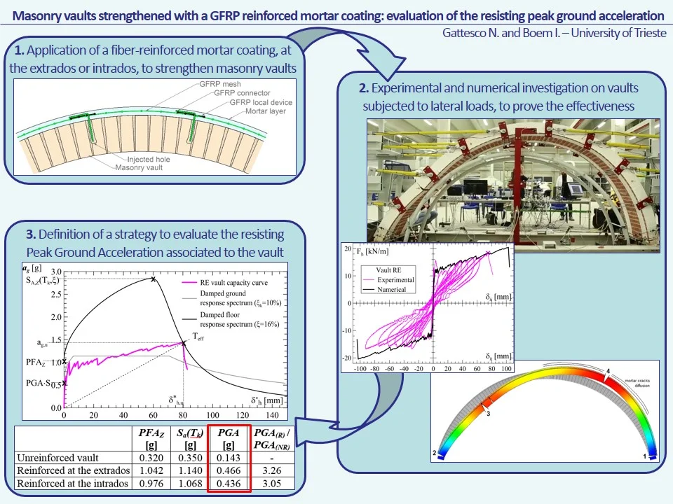
The reinforcement of existing masonry vaults against seismic actions is an extremely timing issue and it has already involved many researchers in experimental testing and numerical modelling. However, up to now, the results of the research have been expressed and compared in terms of load-displacement capacity curves. But the designers, in the practice, need to assess the resisting peak ground acceleration of the vault (PGA), so to compare it with the seismic demand. In the paper, a strategy to evaluate this parameter, based on the modified Capacity Spectrum Method and accounting for the level of the vault in the building is proposed. The procedure is applied to a case study of a masonry building with barrel vaults, comparing the performances of plain vaults and vaults strengthened with a GFRP (Glass Fiber Reinforced Polymer) reinforced mortar coating. The results evidenced significant improvements in terms of PGA after the reinforcement, attaining to values from 3.1 to 3.3 times that of the unreinforced vault.
Highlights
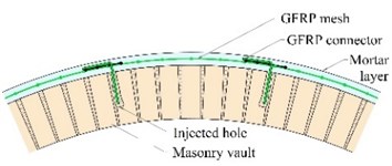
- Application of a fiber-reinforced mortar coating, at the extrados or intrados, to strengthen masonry vaults
- Experimental and numerical investigation on vaults subjected to lateral loads, to prove the effectiveness
- Definition of a strategy to evaluate the resisting Peak Ground Acceleration associated to the vault
1. Introduction
Masonry vaults are important structural components of the architectural heritage of most European cities, but they have a high seismic vulnerability, which caused numerous collapses or severe damages of them, as evidenced the recent Italian earthquakes (L’Aquila 2009, Emilia 2012, Central Italy 2016-2017). Thus, it is necessary to improve their seismic performances, guaranteeing both safety and preservation.
The coupling of fabrics or meshes made of non-corrosive materials (e.g. based on glass or carbon fibers, as well as stainless steel) with inorganic matrices is gradually becoming a common intervention practice, considering the good chemical and mechanical compatibility with the historical masonry [1-4]. The effectiveness of this technique, known as FRM (Fiber-Reinforced Mortar) for the strengthening of vaulted elements has already been tested: a detailed state of art can be found in [5].
The authors recently investigated experimentally, through quasi-static cyclic tests, the effectiveness of a FRM intervention strategy for the strengthening of existing masonry vaults based on the application of a mortar coating with GFRP composite meshes embedded [5]. Moreover, a numerical model based on nonlinear analysis was developed, so to reproduce the performances of the vaults at the varying of their geometrical and mechanical characteristics [6].
However, up to now, all experimental and numerical results have been expressed and compared in terms of capacity curves representing the trend of the horizontal transversal force acting on the vault at the varying of the horizontal displacement at the keystone. But the designers, in the practice, need to assess the seismic response of the vault in terms of resisting peak ground acceleration, so as to compare it with the seismic demand.
Thus, in the paper, a strategy to evaluate the vault resisting ground acceleration is proposed. In particular, the method is based on the transformation of the vault force-displacement capacity curve in the acceleration-displacement capacity curve of the equivalent single degree of freedom system. Then, by applying the modified Capacity Spectrum Method, based on the vault equivalent viscous damping, the resisting peak floor acceleration (PFA, at the level of the vault skewbacks) is evaluated. The resisting peak ground acceleration (PGA) is then derived accounting for the building seismic response and for the vault level, according to the model proposed by Degli Abbati et al. [7], which correlates the floor and the ground response spectra. The procedure is then applied to a case study of masonry building with barrel vaults, so to compare the PGA of unreinforced vaults and vaults strengthened with the GFRP reinforced mortar coating.
2. Behavior of GFRM reinforced vaults subjected to lateral loads
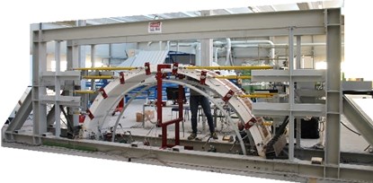
The Glass Fiber-Reinforced Mortar (GFRM) strengthening technique (Fig. 1(a)) consists in the application, at the extrados or intrados of the vault, of a 30 mm thick mortar layer with GFRP meshes embedded and linked to the masonry by means of GFRP connectors. The authors recently performed experimental quasi-static cyclic tests on full-scale samples (Fig. 1(b)) so to assess the effectiveness of the GFRM technique for enhancing the lateral performances of masonry vaults carrying their own self-weight (shelters, without any backfill) [5].
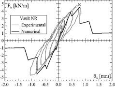
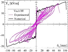
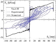
The - experimental capacity curves, representing the trend of the global horizontal load per unit of width at varying of the horizontal displacement at the keystone are plotted in Fig. 1(c)-(e) for three different samples. The vaults, carrying their own weight, have a thickness of 120 mm, a span of 4000 mm and a rise/radius ratio equal to 0.75; one was unreinforced (NR), one reinforced at the extrados (RE) and one at the intrados (RI).
Fig. 1Tests on masonry vaults: a) schematization of the GFRM reinforcement technique for masonry vaults; b) test setup and experimental-numerical curves of three masonry barrel vaults subjected to lateral cyclic load: c) unreinforced vault, d) vault reinforced at the extrados and e) vault reinforced at the intrados
a)
b)
c)
d)
e)
At the increasing of , the formation of horizontal cracks occurred, due to the vault bending. The failure mechanism (formation of four hinges at the skewbacks and at the haunches, in an alternate position intrados-extrados) developed rapidly in the unreinforced sample; differently, in reinforced ones, the collapse was delayed: in fact, when the mortar layer cracked, the GFRP mesh opposed to the hinge opening, maintaining the bending capacity. Only at very large displacements (about 100 times that of the unreinforced vault), when the GFRP mesh rupture occurred, the reinforced samples collapsed, for a horizontal peak load from 3 to 3.8 times that of unreinforced sample.
A simplified model able to reproduce numerically, through non-linear static analysis, the behavior of unreinforced and reinforced masonry vaults subjected to a load acting in the transversal direction has been developed by the authors through the software Midas FEA [6].
The numerical model was bi-dimensional and 4-node “plane strain” elements were used to represent both the masonry and the mortar layer in the thickness; the GFRP wires were modelled by means of truss elements connected to the mortar. A “smear-crack model” and a “total strain crack” criteria were assumed; moreover, localised discrete cracking interfaces were introduced at the skewbacks. The model was adopted to simulate the three experimental tests: even based on monotonic loading and no-slip assumption of cracked sections, it provided fairly good predictions of the experimental results (Fig. 1(c)-(e)).
3. Method
Starting from the - capacity curve of a vault (which can be assessed experimentally, numerically or analytically), the proposed procedure permits to calculate the resistant ground acceleration associated to the collapse of a vault located at a generic level of a building, induced by a horizontal inertia forces acting transversally to the vault axis.
As emerged in the experimental campaign and evidenced also by Ramaglia et al. [8], the lateral performances of slender vaults, subjected only by their self-weight, are governed by the bending strength of the masonry (unreinforced or reinforced), rather than the rocking of the three rigid blocks that occurs once the kinematic mechanism activates (Fig. 2). Therefore, the kinematic analysis (linear or non-linear) is not appropriate for these elements and the capacity curve before the mechanism activation has to be considered.
Fig. 2Collapse mechanism of an arch subjected to lateral forces [9]
![Collapse mechanism of an arch subjected to lateral forces [9]](https://static-01.extrica.com/articles/20409/20409-img6.jpg)
According to Eurocode 8 [10] and FEMA 274 [11], the - capacity curve of the multi degree of freedom (MDOF) system is firstly transformed to the acceleration-displacement - capacity curve of an equivalent single degree of freedom (SDOF) system:
where the equivalent mass of the SDOF system and the transformation factor were evaluated by applying Eq. (3) and Eq. (4), which depend on the mass and the normalised displacement of the -th vault portion:
Among the different procedures available in the literature for the evaluation of the seismic capacity (as the N2 method [12] or the coefficient and secant methods [11]), the modified Capacity Spectrum Method, based on equivalent viscous damping was adopted [11, 13]. This procedure was preferred to the N2 method suggested in Eurocode 8 [10], as the hysteretic behaviour of masonry structures is far away from that of reinforced concrete structures from which the N2 method was derived.
In general, the method, schematized in Fig. 3 in a pseudo-acceleration versus spectral displacement diagram, consists in finding the damped Acceleration Displacement Response Spectrum (ADRS) that intersects the - capacity curve at the target displacement (corresponding, in this case, to activation of the vault collapse mechanism: ). The damped spectrum accounts for the dissipative capacity of the analysed element through the equivalent damping , which can be evaluated accounting for the inherent viscous damping (commonly assumed equal to 5 % in masonry structures) and the hysteretic damping :
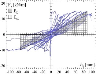
The hysteretic damping, which can be assessed by means of cyclic tests, depends on the ratio between the dissipated energy and the maximum strain energy (Fig. 3):
Fig. 3Evaluation of the equivalent viscous damping for the application of the modified capacity spectrum method [11]
![Evaluation of the equivalent viscous damping for the application of the modified capacity spectrum method [11]](https://static-01.extrica.com/articles/20409/20409-img7.jpg)
However, it is observed that the spectrum to consider for the application of the modified Capacity Spectrum Method is not that referred to the ground: in fact, it is necessary to take into account the variation of the acceleration due to the position of the vault in the building and, thus, to refer to a floor spectrum. Degli Abbati et al. [7] proposed the evaluation of the floor spectrum starting from two points:
• The peak floor acceleration ;
• The maximum floor spectral acceleration evaluated in correspondence of the natural period of the building.
In the case of regular buildings with rigid floors and without torsional problems, it is possible to consider the following simplified formulations:
Being the ground spectral acceleration, the building height, the number of storeys, the level of the secondary element (the vault), 0.05 for masonry buildings and amplification factor for :
The effective damping correction factor of the building, , depends on its equivalent damping , according to Eq. (10):
Similarly, the effective damping correction factor of the secondary element, , depends on its equivalent damping , according to Eq. (11):
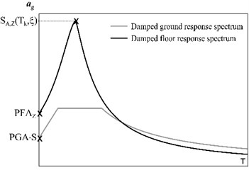
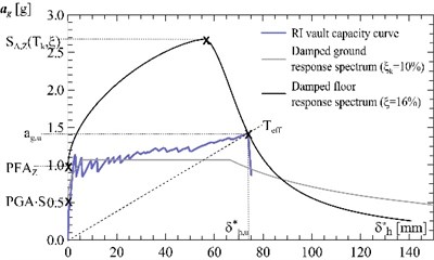
The damped floor response spectrum (Fig. 4(a)) is described through the following analytical function:
where is the ground response spectrum.
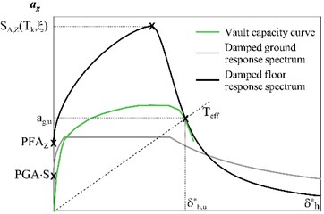
Thus, to evaluate the resisting peak ground acceleration associated to the collapse of the vault at a generic level of the building, the effective period referred to the vault collapse, , has to be calculated in function of the acceleration and of the equivalent displacement associated to the collapse point (, ):
Then, in Eq. (12), it is assumed and and is replaced with Eq. (7). Solving for , the ground spectral acceleration is evaluated:
The resisting peak ground acceleration, PGA, associated to the vault collapse is derived accounting for the ground response spectrum shape. In particular, in case of short periods range, it results:
where is the soil factor.
The procedure is schematised in the ADRS graph in Fig. 4(b).
Fig. 4a) Ground and floor damped response spectra, b) schematization of the procedure adopted for the evaluation of the resisting ground acceleration PGA associated to the vault collapse
a)
b)
4. Characteristics of the case study
The examined case study concerns in a regular building (in plan and in height) made of solid bricks masonry, with rigid floors and three levels (interstorey height 3500 mm). This structure has already been considered by Degli Abbati et al. [7] as an example for the calculation of the floor spectrum (Fig. 5).
Fig. 5Main features of the masonry building considered for the case study [7]
![Main features of the masonry building considered for the case study [7]](https://static-01.extrica.com/articles/20409/20409-img10.jpg)
It is assumed the presence of masonry barrel vaults at the ultimate level of this structure (vault spring sections at 9 m). The vaults, carrying their own weight, have a thickness of 120 mm, a span of 4000 mm and a rise/radius ratio equal to 0.75, similarly to those studied experimentally and numerically (Section 2).
5. Results and discussion
The performances of the vaults before and after the GFRM reinforcement intervention at the extrados or at the intrados are calculated and compared in terms of resisting peak ground acceleration (PGA), according to the procedure described in Section 3. In particular, the numerical capacity curves reported in Fig. 1(c)-(e) are considered.
The main parameters are summarized in Table 1: the mass () and maximum resistance (), expressed for a unitary vault portion, and the displacement at collapse () of the MDOF systems as well as the equivalent mass (), the participation factor (), the collapse acceleration () and the displacement () of the SDOF systems are reported.
Table 1Main parameters of the MODF and SDOF systems
ID | MDOF | SDOF | ||||||
[kg/m] | [kN/m] | [mm] | [kg/m] | [–] | [g] | [mm] | ||
Unreinforced vault | NR | 1318 | 4.80 | 1.084 | 949 | 1.143 | 0.451 | 0.948 |
Vault reinforced at the extrados | RE | 1652 | 19.68 | 90.08 | 1235 | 1.127 | 1.441 | 79.93 |
Vault reinforced at the intrados | RI | 1629 | 19.32 | 82.94 | 1233 | 1.123 | 1.422 | 73.86 |
The vault equivalent viscous damping has been evaluated from the experimental cyclic capacity curves (Fig. 1(c)-(e)), according to Eq. (6) and referring to the last loading cycle before the vault collapse. Values of of about 16 %, both for the unreinforced and the reinforced vaults, were obtained and then it was assumed 0.69 (Eq. (11)).
For the building, it was considered 10 % ( 0.816 Eq. (10)) and a soil factor 1.2.
Fig. 6Unreinforced vault: a) evaluation of the equivalent viscous damping ξ from the experimental cyclic tests, b) calculation of the resisting peak ground acceleration
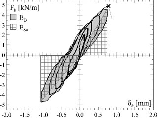
a)
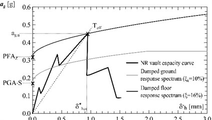
b)
Fig. 7Vault reinforced at the extrados: a) evaluation of the equivalent viscous damping ξ from the experimental cyclic tests, b) calculation of the resisting peak ground acceleration
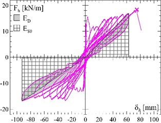
a)
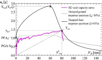
b)
The results are summarized in Table 2: the unreinforced vault collapses for 0.143 g, that is a value which can be exceeded in areas affected by a moderate seismicity (> 0.15 g). The reinforced vaults show significant improvements, reaching values of of 0.466 g (GFRM at the intrados) and 0.436 g (GFRM at the extrados), that affect only very high seismicity areas.
It is worth noting that the evaluations have been conducted assuming for the building a constant equivalent viscous damping (). Reasonably, for the levels achieved in the reinforced cases, the building itself may attain to the near collapse condition; thus, actually, higher damping values should be considered [14] and, thus, the building would greater attenuate the acceleration transmitted from the ground to the vault level, as also highlighted in [7]. However, the calculated values are on the safe side.
Fig. 8Vault reinforced at the intrados: a) evaluation of the equivalent viscous damping ξ from the experimental cyclic tests, b) calculation of the resisting peak ground acceleration
a)
b)
Table 2Main results related to the three analysed vault configurations: effective period referred to the vault collapse Teff, peak floor acceleration PFAZ, ground spectral acceleration SaTk, resisting peak ground acceleration PGA, and ratio between PGA of reinforced (suffix “R”) and unreinforced (suffix “NR”) vaults
– | ID | [s] | [g] | [g] | [g] | / |
Unreinforced vault | NR | 0.092 | 0.320 | 0.350 | 0.143 | – |
Vault reinforced at the extrados | RE | 0.473 | 1.042 | 1.140 | 0.466 | 3.26 |
Vault reinforced at the intrados | RI | 0.457 | 0.976 | 1.068 | 0.436 | 3.05 |
6. Conclusions
In the paper, a method to assess the resisting peak ground acceleration associated to the vault collapse in a masonry building is presented, referring to a lateral load acting in the transversal direction. This strategy is useful for the designers, as permits to assess the vault seismic response in comparison with the seismic demand of the area.
The method is based on the modified Capacity Spectrum Method and is capable to account of the dissipative capacities of both the vault and the building (by means of the respective equivalent viscous damping) as well as of the level of the vault in the building (through the floor response spectrum).
A case study of a masonry barrel vault in a traditional, regular masonry building is analysed. The resisting peak ground accelerations associated to the vault collapse before and after the strengthening interventions by means of the GFRM technique are evaluated and compared. The technique is based on the application, at the vault intrados or extrados, of a 30 mm thick mortar layer with GFRP meshes embedded. In particular, the vaults capacity curves are derived from a previous experimental and numerical study recently carried out by the authors. An estimation of the vault dissipative performances was done, resulting, in the considered cases, in a 16 % equivalent viscous damping at collapse for both the unreinforced and the reinforced configurations.
The results evidenced a modest value of for the unreinforced vault (0.14 g), while significantly higher values after the reinforcement application, ranging from 0.44 g (GFRM at the intrados) to 0.47 g (GFRM at the extrados).
References
-
Briccoli Bati S., Rovero L., Tonietti U. Strengthening masonry arches with composite materials. Journal of Composite Constructions, Vol. 11, Issue 1, 2007, p. 33-41.
-
Alecci V., Focacci F., Rovero L., Stipo G., De Stefano M. Extrados strengthening of brick masonry arches with PBO-FRCM composites: experimental and analytical investigations. Composite Structures, Vol. 149, 2016, p. 184-96.
-
De Santis S., Roscini F., De Felice G. Retrofitting masonry vaults with basalt textile reinforced mortar. Key Engineering Materials, Vol. 747, 2017, p. 250-257.
-
Garmendia L., Larrinaga P., San Mateos R., San-José J.-T. Strengthening masonry vaults with organic and inorganic composites: an experimental approach. Materials and Design, Vol. 85, 2015, p. 102-14.
-
Gattesco N., Boem I. Experimental behavior of non-structural masonry vaults reinforced through fibre-reinforced mortar coating and subjected to cyclic horizontal loads. Engineering Structures, Vol. 172, 2018, p. 419-431.
-
Gattesco N., Boem I. Parametric study on the seismic behavior of masonry vaults strengthened with composite reinforced mortar. Proceedings of the 10th International Masonry Conference, Milan, Italy, 2018.
-
Degli Abbati S., Cattari S., Lagomarsino S. Proposal of floor spectra for the verification of non-structural elements and local mechanisms in masonry buildings. Proceedings of the 17th National Conference on Seismic Engineering ANIDIS, Pistoia, Italy, 2017.
-
Ramaglia G., Lignola G. P., Prota A. Collapse analysis of slender masonry barrel vaults. Engineering Structures, Vol. 114, 2016, p. 86-100.
-
Clemente P. Introduction to dynamics of stone arches. Earthquake Engineering and Structural Dynamics, Vol. 27, 1998, p. 513-522.
-
EN 1998-1:2004: Eurocode 8: Design of Structures for Earthquake Resistance – Part 1: General Rules, Seismic Actions and Rules for Buildings. Brussels, 2004.
-
FEMA274: NEHRP Commentary on the Guidelines for the Seismic Rehabilitation of Buildings. Building Seismic Safety Council, Washington, 1997.
-
Fajfar P. Capacity spectrum method based on inelastic demand spectra. Earthquake Engineering and Structural Dynamics, Vol. 28, 1999, p. 979-993.
-
Freeman S. A. Review of the development of the capacity spectrum method. ISET Journal of Earthquake Technology, Vol. 41, Issue 1, 2004, p. 1-13.
-
Gattesco N., Boem I. Assessment of the seismic capacity increase of masonry buildings strengthened through the application of GFRM coatings on the walls. International Journal of Masonry Research and Innovation, Vol. 2, Issue 4, 2017, p. 300-320.
About this article

The financial supports of “Reluis 2017” and of “Fibre Net S.r.l.” (Pavia di Udine, Italy) are gratefully acknowledged.
