Abstract
This paper describes the soil-structure interaction (SSI) effects to the Nuclear Power Plant (NPP) structure with reactor VVER-1200/491 PWR. The simplified 1D and numerical 3D FE models of the layered subsoil are investigated. The methodology of the calculation of the frequency dependent complex functions of the soil stiffness and damping is presented.
1. Introduction
After the accident of nuclear power plant (NPP) in Fukushima the IAEA in Vienna adopted a large-scale project “Stress Tests of NPP”, which defines new requirements for the verification of the safety and reliability of NPP. Based on the recommendations of the ASCE standard [1] and IAEA in Vienna [2, 3], the effective seismic resistance of objects is assessed in PGA sites up to 0.3 g according to the “Seismic Margin Assessment” methodology (SMA) [4].
The required methodology was based on a reference earthquake (RLE) or a “Seismic Margin Earthquake” (SME) earthquake, which is an earthquake with seismological parameters of a given site and response spectrum at the free terrain level corresponding to 84.1 % probability of non-elevation (median overs), including Peak Ground Acceleration (PGA) for a given acceptable annual occurrence probability (typically 10-4/year). The dynamic soil-structure interaction can sometimes modify significantly the stresses and deflections of the whole structural system. Hence, the following problems should be considered in the dynamic soil-structure interaction models:
1. Radiation of dynamic energy into the unbounded soil;
2. The hysteretic nature of soil damping;
3. Separation of the soil from the structure;
4. Possibility of soil liquefaction under seismic loads; and
5. Other inherent nonlinearities of the soil and the structure.
2. Stiffness and damping soil parameters in the subsoil
Dynamic soil characteristics are obtained with sufficient accuracy from the refractive and reflexive survey of a given site [5-9]. Depending on the propagation rates of the longitudinal and transverse waves in the soil, we can determine its physical characteristics [5, 8, 10]. The basic rigid parameter characterizing the earth body for dynamic calculations is the dynamic (or Young’s elastic modulus modulus):
where is the density (density), – the velocity of the shear waves propagation in the respective earth (layer), is the velocity of the longitudinal waves.
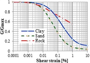
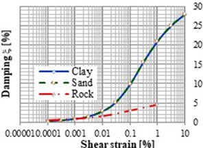
In the case of earthquakes, there is a large movement of the soil, and because of plastic deformation, the value of the dynamic soil module also drops. According to the recommendations of international standards, this reduction will maximally reach 65 % of the dynamic module measured for small seismic events. The process of the shear modulus and the damping can be seen in Fig. 1 depending on the shear strain [8].
Fig. 1Shear modulus dependence on the shear strain and proportional damping
a)
b)
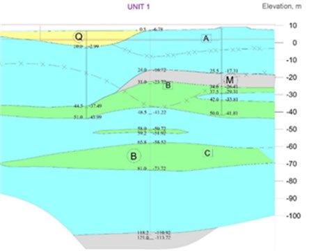
The geology profile under the real NPP main building can be complicated in plane and in depth as in the case of the NPP type VVER 1200 in Turkey. The geology profile in real NPP building was determined from the 12 surveys (see Fig. 2).
Fig. 2Engineering geological cross-section under NPP main building
On the base of the experimental testing of the dynamic characteristics of the subsoil under the foundation plate the homogenisation value of the shear velocity was determined. The comparison of the shear velocity calculated by the different methodology is presented in Table 1. We can see, that the scatter of the values of the shear velocity in this area is equal about 250 %.
Table 1Comparison of Vs.30 parameters, determined with the use of different methods [11]
Bore hole | Borehole elevation [m] | [m/s] | |||
PS-logging | Micro-tremor | Down-hole | ReMi/MASW | ||
199 | 7.28 | 707 | 1200 | 1470 | 1050 |
1076 | 6.93 | 860 | 1200 | 1800 | 1050 |
221 | 7.79 | 820 | 1200 | 1370 | 1050 |
3. Simplified model of the global subsoil stiffness and damping under foundation plates
The dynamic stiffening characteristics of the subsoil depend not only on the physical and mechanical properties of the soil, but also on the shape and depth of the base structure [5, 10, 12-19]. Some authors consider the soil stiffness of rectangular foundation by the equivalent diameter of circular plate:
The rectangular foundation plate with the dimensions in plane . has plate area . . The stiffness intensity of soil is equal to (, , , ), when is the global soil stiffness.
Various authors define the subsoil dynamic stiffness and damping under rigid rectangular plate as follows:
a) The global soil stiffness under rectangular plate according to ASCE4/98 [1] are defined as follows:
where axis and are in the horizontal plane and is in vertical direction, , are the coefficients depended on the ratio , rotated coefficient for (e.g. for ) (see Fig. 3).
Fig. 3Coefficients βx, βz, βψ for rectangular foundation [1]
![Coefficients βx, βz, βψ for rectangular foundation [1]](https://static-01.extrica.com/articles/20423/20423-img4.jpg)
The damping characteristics are determined from the assumption of their proportionality to the spring stiffness of the substrate. The calculation of damping characteristics according to ASCE 4/98 [1]:
where , , , , , are global spring constants, , , , , , – global damping constants, – soil mass, – dynamic shear modulus, – polar mass moment of structure and baseman, – baseline radius, – torsional radius .
b) The global soil stiffness under rectangular plate according to Pais and Kausel [10] and considering the homogeneous half space and the ratio of the base dimensions () are defined as follows:
c) The global soil stiffness under rectangular plate according to Gazetas [5] for the rigid block and elastic half space are defined as follows:
where total damping for – hysteretic damping parameter, dynamic stiffness can be calculated as for dynamic stiffness coefficient and the damping coefficient , , , , and can be used from the nomograms depending on the ratio and parameter , where is the soil shear velocity.
Table 2Global stiffness of foundation plate of the subsoil under foundation plate (ASCE4/98) [1]
Subsoil | ||||||
Model | [GN/m] | [GN/m] | [GN/m] | [GNm/m] | [GNm/m] | [GNm/m] |
Lower | 652.37 | 652.37 | 832.70 | 1312006.62 | 1465439.38 | 1571823.62 |
Mean | 1177.81 | 1177.81 | 1568.70 | 2471638.32 | 2760684.33 | 2747898.45 |
Higher | 2238.36 | 2238.36 | 3140.18 | 4947649.83 | 5526253.27 | 5054915.83 |
Table 3Global damping of foundation plate of the subsoil under foundation plate (ASCE4/98) [1]
Subsoil | ||||||
Model | [GN/s.m] | [GN/s.m] | [GN/s.m] | [GNm/s.m] | [GNm/s.m] | [GNm/s.m] |
Lower | 652.37 | 652.37 | 832.70 | 1312006.62 | 1465439.38 | 1571823.62 |
Mean | 586.59 | 582.95 | 800.93 | 1175538.99 | 1059826.64 | 1353431.86 |
Higher | 572.36 | 568.13 | 773.47 | 959877.17 | 1063753.60 | 1471148.84 |
In the case of the layered subsoil, the equivalent material characteristics can be determined from the 1D model on the base of the theory of the series springs. The standard ASCE4/98 [1] require using 3 level of the soil stiffness – lower, mean, higher. The ratio between these models is equal to 1.5. It is equivalent to the uncertainties of the soil stiffness and damping due to simplified calculation models (see Tables 2 and 3).
4. General principles of structural-base interaction
For most common structures, the effect (SSI) of the structure-substrate interaction will be more advantageous as it reduces the effect of bending moments and shear forces on individual structural elements. The effect of the dynamic soil-structure interaction must be considered for all foundations [5, 6, 10, 16, 20]:
• Method of direct integration.
• Method of impedance functions.
The effect of foundation depth is considered when an object is laid at a depth greater than 6m.
The direct method of the design and substrate interaction consists of the solution of the following tasks:
• Localize the contact between the structure and the subsoil,
• Define the seismic load at the level of the base joint,
• Create the calculation model subsoil, its properties, soil layering under the foundation,
• Carry out the interaction in one or two steps,
If the direct method is considered, the stiffness and attenuation of the substrates can be modelled as a set of independent springs or, in more detail, based on the finite element method.
The impedance function method [9, 20] consists of the following steps:
• Determine the seismic load assuming a rigid base,
• Determine impedance functions for given foundations,
• To analyse the interactions between the structure and the base.
The impedance functions define the dependence of stiffness and subtle stress on the substrate based on frequency. It is assumed that the harmonic force is applied to the rigid base deposited on the flexible half-frame. Such a computational model. assuming linear behaviour. provides a better understanding of the properties of the underlying behaviour. depending on the actual frequencies of the structure itself.
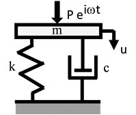
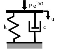
In the case of a simple base model and substrate. the impedance functions are determined by the ratio of the harmonic force acting on the rigid base to its displacement in the shape:
where (resp. ) represent the stiffness (resp. attenuation) of the substrates, is the weight of the base, is the circular frequency (see Fig. 4).
Fig. 4Calculation model of base with mass m and without weight
a)
b)
5. Impedance of foundation using FE model
For complex foundation geometries or soil conditions, the dynamic soil impedance can be determined by dynamic analysis of a three-dimensional or two-dimensional continuum model of the soil-foundation system. The six steps can be implemented using the finite element (FE) method [21, 11, 18, 22]. In this case, the soil is modelled as an elastic or viscoelastic material, which can be considered isotropic, anisotropic, homogeneous or nonhomogeneous. In a FE model, only a portion of the soil (i.e., a soil island) can be discretized; therefore, appropriate boundary conditions (non-reflective boundaries) must be applied where the soil is arbitrarily truncated. The response of a rigid foundation to static or dynamic load arises solely from the deformation of the supporting soil. The static soil stiffness () is used to model the soil-foundation response to static load. In an analogous manner, the dynamic soil impedance/stiffness () is used to model the soil-foundation response to dynamic loads. In particular, six dynamic impedances are required, three translational and three rotational, to formulate the dynamic equilibrium equation of a rigid foundation. These impedances are a function of the foundation geometry, the soil properties and vibration frequency of the dynamic loads (, ).
The procedure used to calculate the dynamic impedances of a rigid surface foundation can be summarized in the following steps:
1. The foundation can be modelled as massless and infinitely rigid; therefore, only the geometry of the area in contact with the soil is required. The use of a massless foundation is important since it avoids the need for recalculating the dynamic impedance every time that the foundation mass changes, which often happens during the design process.
2. A harmonic force or moment of frequency and of unit magnitude is applied to the rigid foundation []. Such force/moment generates stress waves that propagate into the underlying soil, which is modelled as a viscoelastic material.
3. The steady state vibration amplitude [ or ] of the foundation under the harmonic force is obtained by keeping track of the reflections and refractions that take place every time that the stress waves reach a soil layer boundary.
4. The dynamic impedance is defined as the ratio between the harmonic force acting on the foundation and its vibration amplitude as shown in Eq. (7). It must be noted that this is a frequency dependent complex quantity:
5. In soil dynamics, it is customary to express the complex dynamic impedance. In addition, the real and imaginary parts of the dynamic impedance are associated, by analogy, with a dynamic (frequency dependent) spring and dashpot as shown in following equations:
Steps 2 to 5 are repeated for each frequency of interest, until the range of vibration frequencies of the machine is covered.
6. Calculation FE model
The presented methodology was used for the analysis of the soil-structure interaction of the NPP main building with reactor VVER1200 which was situated in the complicated subsoil area [11]. The dimension of the reactor building is 83.8 m×78 m in plane and 74.9 m in high. The thick of the foundation plate is equal to 2.65 m. The total building masses and the gravity centre position is following – Mass = 351 ton, –0.304 m, 0.205 m; 22.08 m. The dynamic characteristics of the layered subsoil were determined by the experimental investigation of the region. The mean value and the standard deviation of the shear velocity for the 30 m depth are following – (mean) = 1069 m/s, (st.dev) = 96 m/s.
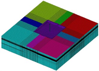
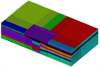
The subsoil around the NPP main building VVER-1200/491 PWR is modelled by solid elements SOLID185, the foundation plate by shell elements SHELL181 and surface around soil block by elements SURF154 in the software ANSYS (see Fig. 5).
Fig. 5FE model of the subsoil under NPP main building (231.226 elements, 91 materials)
a)
b)
7. Impedance functions of NPP main building
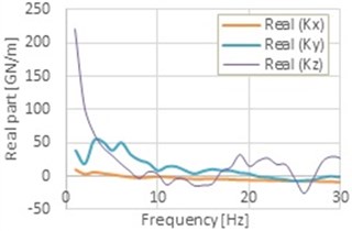
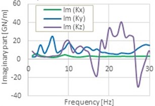
On the base of the methodology presented in chap. 6 the impedance functions for the NPP main building VVER-1200/491 PWR considering the real layered subsoil properties determined by experimental testing of the subsoil were calculated on FE model in software ANSYS (see Fig. 6). The impedance functions shape in Fig. 6 are not simple and continuous functions as in the case of the analytical solutions of the impedance functions of the rigid plate on layered soil [18]. The layered properties of the soil under rigid plate and the discretisation of the subsoil using FE Model with the solid elements give us more detailed information’s of the dynamic soil-structure interaction effects. The global stiffness and damping properties depend on the geometry and material properties of the soil under the rigid rectangular plate.
Fig. 6Real and imaginary part of the global impedance functions for translation
a)
b)
8. Conclusions
This paper describes the soil-structure interaction effects in the case of the NPP main buildings with reactor VVER-1200/491 PWR during earthquake excitation. The methodology of the calculation of the impedance functions were considered [11]. The dynamic impedance is defined as the ratio between the harmonic force acting on the foundation and its vibration amplitude. The results from the 3D FE analysis show as that the impedance functions are not smooth functions in case of the layered subsoil with various material properties as in case of the homogeneous subsoil.
References
-
ASCE 4-98 Seismic Analysis of Safety Related Nuclear Structures. ASCE Standard, 2000.
-
Safety Series 50-SG-S1, Earthquake and Associated Topics in Relation to Nuclear Power Plants Siting. Rev.1, IAEA, Vienna, 1992.
-
Revised Safety Guide No, NS-G-3.3, Evaluation of Seismic Hazards for Nuclear Installations, Safety Guide DS422. IAEA Vienna, 2008.
-
A Methodology for Assessment of Nuclear Power Plant Seismic Margin, Rep. EPRI NP-6041-SL. Rev. 1, EPRI, Palo Alto, CA, 1991.
-
Gazetas G. Foundation Vibrations in Foundation Engineering Handbook. Van Nostrand Reinhold, New York, 1991.
-
Chen W. F., Scawthorn Ch. Earthquake Engineering Handbook. CRC Press, Taylor and Francis Group, 2003.
-
Jaya V. G., Dodagoudar R., Boominathan A. Seismic response analysis of nuclear island building: A case study. Journal of Structural Engineering (Madras), Vol. 38, Issue 3, 2011, p. 217-229.
-
Placzek D. Bodendynamik, Einfurhrung und Grundlagen, University of Gesam-thochschuls. Essen, 1986.
-
Sieffert J. G., Cevaer F. Handbook of Impedance Functions. ECN Nantes, 1991.
-
Wolf J. P. Foundation Vibration Analysis Using Simple Physical Models. Prentice Hall, Englewood Cliffs, 1994.
-
Králik J. Soil-Structure dynamic interaction of NPP on the layered subsoil, methodology. Report 0086-A*3*1-UJDM-1/17, Bratislava, 2017.
-
Krejsa M., Čajka R. The foundation slab monitoring of the National Supercomputing Centre - IT4 Innovations during construction. Proceedings of the 11th International Probabilistic Workshop, Brno, 2013, p. 219-233.
-
Kotrasova K., Hegedusova I., Harabinova S., Panulinova E., Kormanikova E. The possible causes of damage to concrete tanks, numerical experiment of fluid-structure-soil interaction. Key Engineering Materials, Vol. 738, 2017, p. 227-237.
-
Králik J., Šimonovič M. Earthquake response analysis of nuclear power plant buildings with soil-structural interaction. Mathematics and Computers in Simulation, Vol. 50, Issues 1-4, 1999, p. 227-236.
-
Králik J., Králik J. Jr. Probability and sensitivity analysis of soil-structure interaction of high-rise buildings. Slovak Journal of Civil Engineering, Vol. 14, Issue 2006, 3, p. 18-32.
-
Králik J. Safety and Reliability of Nuclear Power Buildings in Slovakia. Earthquake-Impact-Explosion. STU Bratislava, 2009, p. 307.
-
Králik J. Risk-based safety analysis of the seismic resistance of the NPP structures. 8th International Conference on Structural Dynamics, Eurodyn, Leuven, Belgium, Vol. 2, 2011, p. 292-299.
-
Maravas A., Mylonakis G., Karabalis D. L. Dynamic analysis of flexible foundations based on a discrete impedance matrix approach. Eurodyn, Porto, 2014, p. 675-679.
-
Novotný J., Kanický V., Salajka V., Štepánek P. Seismic analysis of selected structures of the NPP dukovany – influence of modelling on the corectness of results. 1th International Conference, DYNA, Brno, 2006, p. 229-237.
-
Tyapin A. G. Next generation of soil-structure interaction models for design of nuclear power plants. Journal of Disaster Research, Vol. 9, Issue 1, 2014, p. 3-16.
-
Hou X., Yang X., Wei Q. Rectangular foundations and their applications in dynamic foundation response analysis. 13th World Conference on Earthquake Engineering, Vancouver, Canada, 2004.
-
Werkle H., Volarevic J. Modelling of dynamic soil-structure-interaction in the three-dimensional finite element analysis of buildings. 2nd European Conference on Earthquake Engineering and Seismology, Istanbul, 2014.
Cited by
About this article

The project was performed with the financial support of the Grant Agency SR (VEGA 1/0265/16 and 1/0412/18).
