Abstract
A common analysis method of soil-structure systems in seismic design procedures such as FEMA-440 is to replace the entire soil-structure system by a fixed-base oscillator with an equivalent fundamental period and damping ratio to consider inertial effect of soil-structure interaction. It is generally believed by researchers that ignoring kinematic effect of soil-structure interaction is conservative to determine response of structures and FEMA-440 supports this idea by defining a reduction factor applying to elastic response spectra. Also, the improvements of nonlinear static procedures in FEMA-440 are achieved for fixed-base structures and the soil effects are not perfectly obtained in coefficients and relations of these procedures. Thus, it seems necessary to assess the accuracy of proposed procedures of FEMA-440 to include soil-structure interaction. In this paper, the accuracy of equivalent replacement oscillator and nonlinear static Procedures of Equivalent Linearization and Coefficient methods, defined in FEMA-440, to analyze soil-structure systems with surface and embedded foundations are evaluated. Both kinematic and inertial effects of soil-structure interaction are investigated by conducting a parametric study using 20 ground motions recorded on soft soil site E, on which the more SSI effects are probable.
1. Introduction
Current performance-based seismic design methods use displacement rather than forces as basic demand parameters for design, evaluation and rehabilitation of structures. These methods developed to control earthquake damage of structural elements and many types of non-structural elements by limiting lateral deformation of structures. Also, in current performance-based design, it is desirable to estimate the inelastic demands of structures by simple and accurate analysis methods such as Nonlinear Static Procedures (NSPs). Although these methods have more uncertainty with respect to other nonlinear analysis procedures, but the convenience in practice and their acceptable accuracy made them the most practical ones and the basis of current rehabilitation documents such as FEMA-356 [1] and ATC-40 [2] for calculating inelastic demands of structures. The recent studies also emphasize that current NSPs, to conduct a simple and accurate analysis, play an important role to determine inelastic seismic demands of structures. Researches conducted by Bosco et al. [3], to Predict displacement demand of multi-story asymmetric buildings, by Mazza [4] to analyze reinforced concrete framed buildings, by Wan et al. [5] that propose a new NSP to analyze precast concrete diaphragms and by Foraboschi et al. [6] in analysis of masonry buildings by NSPs are as examples of these recent researches. Some improvements are applied to current NSPs in FEMA-440 [7], but all of equations and relations of these methods are developed for fixed-base structures.
On the other hand, the flexibility of structures’ underlying soil affects the response of the structures due to soil-structure interaction (SSI). This phenomenon has two main effects as follows:
1) The difference between stiffness of the foundation and the surrounding soil induces the difference between the motion experienced by the essentially rigid foundation (the foundation input motion (FIM)) and the free-field motion (FFM). This effect is called the kinematic interaction (KI) effect and happens even if the foundation has no mass. In other words, the FIM is the result of geometric averaging of the seismic input motion in the free field (Meek and Wolf [8]).
2) The flexibility of soil affects the response of the structure subjected to FIM. In fact, the soil-structure system behaves as a new system with different dynamic properties (longer natural period and usually higher damping). This effect is called inertial interaction (II) effect.
Numerous researches on the effects of SSI have been carried out over the past few decades, but generally excluded the nonlinear behavior of structures. Replacing the entire soil-structure system with a fixed-base oscillator to consider II effect is a common analysis method in seismic design procedures. Current SSI-related regulations in seismic codes, such as ATC3-06 [9] and NEHRP [10] are based only on the knowledge of the II effect on elastic response of structures while the KI effect is traditionally ignored. The variations of the equivalent natural period and damping ratio of equivalent replacement oscillator have been studied by other researchers such as Veletsos and Meek [11], Veletsos and Nair [12], Wolf [13] and Aviles and Perez-Rocha [14].
However, the yielding behavior of structures has recently been given more attention by some researchers. Bielak [15] first studied this matter by investigating the harmonic response of a bilinear structure supported on a visco-elastic half-space and found that the resonant structural deformation could be significantly larger than the deformation obtained from the fixed-base structure. However, it could not be determined how the supporting soil affected the ductility or displacement demand of the structures.
Aviles and Perez-Rocha [16] considered single degree of freedom (SDOF) elasto-plastic structures supported on a rigid foundation embedded in a visco-elastic stratum of constant thickness over a uniform visco-elastic half-space. They assumed the fixed parameters in order to represent typical buildings and site conditions in Mexico City and introduced a replacement oscillator with an effective period, damping ratio of elastic condition and effective ductility that was typical of the nonlinear behavior of structure. The results demonstrated that the effects of the foundation flexibility and the yielding of structures are beneficial for slender structures with natural periods somewhat larger than the site period, but detrimental if the structural period is shorter than the site period. Aviles and Perez-Rocha [17] employed this replacement oscillator formulation in the design code of Mexico City and NEHRP [10]. Their investigations also revealed that SSI could have a great influence on the strength reduction factor (SRF) of structures. This result can change the design process specified in design codes such as ATC3-06 [9] to include SSI effects, which determines a new spectral response with effective period and damping without considering the variations of SRF values and leads to underestimating the estimated design base shear. The effect of II on inelastic demands of structures was discussed by Ghannad and Ahmadnia [18], Ghannad and Jahankhah [19] and Behmanesh and Khoshnudian [33] in detail. Inelastic displacement ratios are also modified in soil-structure systems by Eser and Aydemir [20] and Eser et al. [21] in analysis and design procedures, respectively.
Recent studies also indicate that current procedure of defining elastic replacement oscillator should be reconsidered when a structure undergoes a nonlinear displacement demand. So, in recent documents on nonlinear static procedures such as FEMA-440 [7], a modified effective damping ratio for replacement oscillator was proposed by introducing the ductility of the soil-structure system obtained from pushover analysis. Moreover, it is generally believed by researchers that ignoring KI effect is conservative in determining soil-structure systems’ response (Lin and Miranda [22] and Stewart [23]) and FEMA-440 [7] supports this idea by considering the reducing effect of KI due to base slab averaging and foundation embedment. However, it seems that despite the reducing effect of KI on the translational component of the FIM, the resulting rocking component may increase the structural demands especially for soil-structure systems with deep embedded foundations (Mahsuli and Ghannad [24]).
Also, as mentioned above, SSI effects on equations and relations of NSPs are ignored in FEMA-440 [7] regulation. But researches conducted by Madani et al. [25], Durmuş et al. [26], Galvin et al. [27] and Medina et al. [28] are as examples of recent researches that express the considerable effects of SSI on elastic and inelastic demands of structures. Consequently, it seems necessary to assess the accuracy of proposed NSPs of FEMA-440 [7] to consider both Inertial and Kinematic effects of SSI.
In this paper, the accuracy of FEMA-440 [7] procedure to analyze soil-structure systems is evaluated for both surface and embedded foundations. For this purpose, a parametric study is carried out using 20 ground motions recorded on soft soil site E, on which the more SSI effects are probable.
2. Soil-structure model
2.1. Inertial interaction effect
The soil-structure system considered as exact model in this study is shown in Fig. 1(a), which is based on the following assumptions:
1. The super-structure is modeled as an equivalent elasto-plastic SDOF system with height , mass and mass moment of inertia , which may be considered to be the effective values for the first mode of vibration of a real multi degree of freedom (MDOF) structures.
2. The foundation is considered to be a rigid disk with embedment depth and mass and mass moment of inertia and, respectively.
3. The soil beneath the structure is considered as a homogeneous half-space and replaced by a discrete model based on the concept of cone model for embedded foundations (Wolf [29]). In this model, two sway () and rocking () degrees of freedom (DOFs) are introduced for the foundation. An additional internal DOF () is introduced for the soil model to consider frequency dependency of soil’s dynamic stiffness. Representative springs of soil behave elastically, and effect of soil nonlinearity is approximately introduced using a degraded shear wave velocity, consistent with the estimated strain level in soil (Kramer [30]), for the soil medium. According to NEHRP [10] and FEMA-440 [7], the strain level in soil is related to the peak ground acceleration. Consequently, a 4-DOF model is formed for the whole soil-structure system as shown in Fig. 1(b). The structure, foundation and soil related parameters, introduced in Fig. 1(b), are defined as follows:
where, , , , and are the specific mass, Poisson’s ratio, shear wave velocity, the basement embedment and the radius of the equivalent cylindrical foundation, respectively. Besides, , , , and are non-dimensional coefficients of the discrete model in terms of . Sway springs and dashpots are connected to the super-structure with and eccentricities respectively, to consider the coupling terms of the sway and rocking DOFs in the stiffness matrix. In current study, these non-dimensional coefficients are calculated by optimum fitting of the dynamic stiffness coefficients of discrete model with corresponding values of exact results in the case of surface foundation and with cone model’s result in the case of embedded foundation in frequency domain. The results are tabulated in Table 1 for site class E with poison’s ratio, 0.45.
To consider soil material damping, the complex model of Fig. 1(b) is generated according to visco-elastic Voigt model, in which every spring and dashpot in the basic model is augmented with a dashpot and a mass, respectively (Wolf [29]). The whole soil-structure model is subjected to sway and rocking components of FIM ( and ) as shown in Fig. 1(a). More details about components of FIM are described in Section 2.2.
Table 1Non-dimensional coefficients of discrete model for foundation on or embedded in homogeneous half-space with ϑ= 0.45 (site class E)
0 | 0.5 | 1 | 1.5 | |
0.6 | 1.0145 | 1.2354 | 1.3759 | |
– | 0.092285 | 0.19043 | 0.32207 | |
– | 0.13496 | 0.35273 | 0.5916 | |
0.0186 | 0.32337 | 0.3156 | 0.31687 | |
0.359 | 0.31916 | 0.3464 | 0.40138 | |
0.2995 | 0.01296 | 0.01149 | 0.00599 | |
– | 0.00003 | 0.00003 | 0.000002 |
Fig. 1a) The soil-structure system; b) the basic soil-structure model
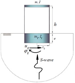
a)
b)
2.2. Kinematic interaction effect
As introduced in soil-structure system of Fig. 1(a), two different FIM components are produced as a result of KI effect: Horizontal FIM () and rocking FIM ().
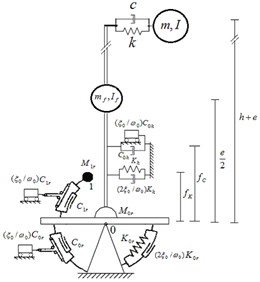
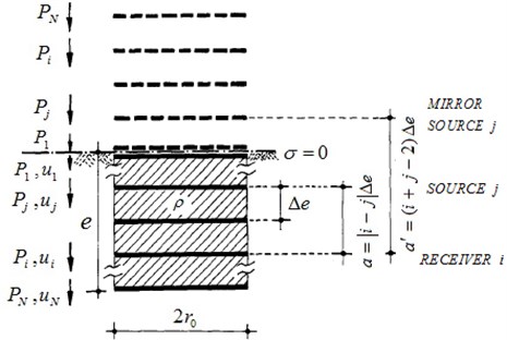
Horizontal FIM component generally decreases in comparison with FFM especially for more embedment depths. But rocking FIM amplitude has an increase as the depth of embedment increases. To evaluate FIM components, Meek and Wolf [8] method is used based on the concept of double-cone models. Double cones are used to represent a disk embedded in a full-space. An embedded foundation is then replaced by a stack of N disks, commencing from the lowermost point of the foundation, e, and continuing to the ground surface. As modeling with cone segments addresses the discretization on the axis in the vertical direction, a sufficient number of disks must be selected to be able to accurately represent the harmonic response for a specified frequency. For this purpose, in this study, the maximum vertical distance between two neighboring disks in term of shear wave length, follows as:
By defining and (frequency of excitation) and considering 4 for common earthquake ground motions, is calculated, in this study, by:
In order to provide stress-free condition on the ground surface, another stack of disks, which are the mirror images of the former disks, are considered on the other side of the ground surface as demonstrated in Fig. 2. These mirror image disks are excited by the same excitations as the original disks, therefore, stress-free condition on the ground surface will be guaranteed. Using the green functions at the level of each disk and its mirror image, the × flexibility matrix of the free field is evaluated. The inverse of this flexibility matrix is the dynamic stiffness matrix of the free field ().
Then by extracting the excavated part of the soil from the model and inserting the rigid foundation, the dynamic stiffness of the embedded foundation can be evaluated. Because the rigid foundation is inserted, the dimension of the stiffness matrix is reduced from to 2, for introduced sway-rocking foundation DOFs. This can be done using a ×2 kinematic condition matrix (), which is calculated based on the foundation geometry. Thus, the dynamic stiffness matrix of the rigid foundation () is calculated using the mass matrix of the excavated part of the soil () as:
The relationship between the dynamic stiffness and motion of the free-field state as well as those of the foundation is:
Subsequently, the FIM vector is evaluated using the following equation:
where, is the ×1 vector of the FFM, evaluated at the level of the disks, and is the 2×1 vector of the FIM, comprising the two components of the sway and rocking motions, as:
2.3. Problem parameters
The response of the soil-structure system depends basically on the size of the structure, its dynamic properties, and the soil profile as well as the applied excitation. According to dynamic properties of soil-structure system and FIM (as defined in Subsections 2.1 and 2.2), the effect of these factors can be best described by the following non-dimensional parameters (Veletsos [31]):
– A non-dimensional frequency as an index for the structure-to-soil stiffness ratio:
where is the circular frequency of the fixed-base structure and is the effective structure height taken as the full height of the building for one-story structures and as the vertical distance from the foundation to the centre of the first mode shape for multi-story structures. The index can have values of up to 3 for conventional building-type structures resting on very soft soil; while infinitesimal values close to zero are representative of fixed-base structures (Ghannad [32]).
– Aspect ratio of the building, an index for its slenderness ratio.
– Embedment ratio of the foundation, defined as .
– Ductility demand of the structure, defined as:
where, and are the maximum displacement caused by a specific base excitation and the yield displacement of the structural stiffness, respectively.
– Strength reduction factor (SRF) of the structure, defined as:
where, and are the strength required to maintain the structure in elastic range and inelastic strength demand of the structure, respectively.
– Structure-to-soil mass ratio index, defined as:
where, is the effective mass for the first mode, calculated as the total mass times the effective mass coefficient. This parameter varies between 0.4 and 0.6 for ordinary building-type structures (Ghannad [32]) and is set equal to 0.5 in this study.
– Foundation-to-structure mass ratio, that is assigned 0.1.
– Poisson’s ratio of soil, that is considered to be 0.45 for soil type .
– Material damping ratios of the structure and of the soil , that both are set to 5 % of the critical damping at the effective period of the soil-structure system.
The first three factors not only participate within higher exponents in the equations of motion but also have a vaster range of variations. Thus, in this study, they are selected as the key parameters of the system. But the other parameters (except or ) are those with less importance and were set to mentioned typical values for ordinary structures.
Fig. 2Model of embedded foundation, stack of N disks and their mirror image
3. FEMA-440 procedure to consider soil-structure interaction
The objective of FEMA-440 [7] procedure to consider SSI is to convert the soil-structure system to its corresponding equivalent fixed-base model and use the analysis procedures determined and optimized for a fixed-base structures. The FEMA-440 [7] procedure to consider SSI effects includes following steps:
1. Evaluate the linear periods for the structural model assuming a fixed-base, and a flexible base, using appropriate foundation modeling assumptions. An estimate of the strain-degraded shear modulus should be used for calculating soil stiffness.
2. Calculate effective structural stiffness of the SDOF oscillator for fixed-base condition as:
3. Determine the equivalent foundation radius for translation as:
where, is the area of the foundation footprint if the foundation components are inter-connected laterally.
4. Calculate the translational stiffness of the foundation, . For many applications, the translational stiffness can be estimated as:
where is effective strain-degraded soil shear modulus and is soil Poisson’s ratio.
5. Calculate the equivalent foundation radius for rotation, by first evaluating the effective rotational stiffness of the foundation, as:
The equivalent foundation radius for rotation is then calculated as:
The soil’s shear modulus, and soil Poisson’s ratio, should be consistent with those used in the evaluation of foundation spring stiffness.
6. Determine the basement embedment, .
7. Estimate the effective period-lengthening ratio, , using the site-specific structural model developed for nonlinear pushover analyses. This period-lengthening ratio is calculated for the structure in its degraded state. An expression for the ratio is:
where, the term is the expected ductility demand for the system, (i.e., including structure and soil effects). Thus, the ductility must be estimated prior to the actual solution and subsequently verified.
8. Evaluate initial fixed-base damping ratio of the structure (), which is often taken as 5 %.
9. Determine foundation damping due to radiation damping, based on, , and , using following equations:
where is in percent and:
10. Evaluate the flexible-base damping ratio from and , as:
11. Evaluate a reduction factor of response spectra () from following equation, as a function of period and embedment depth, if the structure has an embedded basement from the ground surface:
here, is shear wave velocity reduction factor for the expected PGA as estimated from Table 2.
Table 2Approximate values of shear wave velocity reduction factor, n
>0.30 | 0.20 | 0.15 | 0.10 | PGA |
0.65 | 0.70 | 0.80 | 0.90 |
12. Evaluate the effect on spectral ordinates of the change in damping ratio from to , then modify the spectrum of the FIM using RRS. Note that FIM is equal to the FFM if KI effects are neglected.
13. Consequently, nonlinear response of structure should be evaluated using current NSPs and the determined ductility demand should be checked against the value assumed in Step 7 above.
Note that current NSPs to estimate seismic demands of structures are based on the calculation of maximum displacement demand of inelastic SDOF systems, determined by pushover analysis. For instance, FEMA-356 [1] and ATC-40 [2] are two standards that employ NSPs, the so called Coefficient and Equivalent Linearization methods, to estimate the target displacement. The basic concept of the Coefficient Method is to convert the linear elastic displacement of the equivalent SDOF system to its inelastic displacement with some modification factors. In the Equivalent Linearization method, the inelastic equivalent SDOF system converts to its elastic linear equivalent SDOF system. Then, the displacement demands are calculated, using the response or design spectra or linear time history analysis of the equivalent linear elastic SDOF system. The coefficients and relations of NSPs are also modified in FEMA-440 [7] for fixed-base structures.
4. Earthquake ground motions
A total of 20 earthquake ground motions recorded on site condition E (as defined in NEHRP [10] and classified in FEMA-440 [7], Appendix C), which the more SSI effects are probable, are used in this study. The site class E is consisted of ground motions recorded on very soft soil stations with shear wave velocities smaller than 180 m/s. Detailed listings of the ground motions are presented in Table 3.
Table 3Selected ground motions recorded at site class E
PGA (cm/s2) | Dir. | Station No. | Station name | Earthquake name | Magnitude () | Date | No. |
231.5 | 0 | 58223 | San Francisco, International Airport | Loma Prieta | 7.1 | 10/89 | E1 |
322.7 | 90 | 58223 | San Francisco, International Airport | Loma Prieta | 7.1 | 10/89 | E2 |
191.3 | 180 | 58224 | Oakland, Title & Trust Bldg. (2-story) | Loma Prieta | 7.1 | 10/89 | E3 |
239.4 | 270 | 58224 | Oakland, Title & Trust Bldg. (2-story) | Loma Prieta | 7.1 | 10/89 | E4 |
134.7 | 270 | 1590 | Larkspur Ferry Terminal | Loma Prieta | 7.1 | 10/89 | E5 |
94.6 | 360 | 1590 | Larkspur Ferry Terminal | Loma Prieta | 7.1 | 10/89 | E6 |
254.7 | 260 | 1662 | Emeryville, 6363 Christie Ave. | Loma Prieta | 7.1 | 10/89 | E7 |
210.3 | 350 | 1662 | Emeryville, 6363 Christie Ave. | Loma Prieta | 7.1 | 10/89 | E8 |
277.6 | 90 | 58375 | FosterCity(APEEL1;RedwoodShores) | Loma Prieta | 7.1 | 10/89 | E9 |
63.0 | 360 | 58375 | FosterCity(APEEL1;RedwoodShores) | Loma Prieta | 7.1 | 10/89 | E10 |
270.0 | 43 | 1002 | Redwood City (APEEL Array Stn. 2) | Loma Prieta | 7.1 | 10/89 | E11 |
222.0 | 133 | 1002 | Redwood City (APEEL Array Stn. 2) | Loma Prieta | 7.1 | 10/89 | E12 |
112.0 | 0 | 58117 | TreasureIsland | Loma Prieta | 7.1 | 10/89 | E13 |
97.9 | 90 | 58117 | TreasureIsland | Loma Prieta | 7.1 | 10/89 | E14 |
281.4 | 35 | 58472 | Oakland, Outer Harbor Wharf | Loma Prieta | 7.1 | 10/89 | E17 |
265.5 | 305 | 58472 | Oakland, Outer Harbor Wharf | Loma Prieta | 7.1 | 10/89 | E18 |
216.8 | 230 | 5057 | ElCentro Array3, Pine Union School | Imp. Valley | 6.8 | 10/79 | E15 |
260.9 | 140 | 5057 | ElCentro Array3, Pine Union School | Imp. Valley | 6.8 | 10/79 | E16 |
45.1 | 40 | 58375 | FosterCity(APEEL1;RedwoodShores) | Morgan Hill | 6.1 | 04/84 | E19 |
66.7 | 310 | 58375 | FosterCity(APEEL1;RedwoodShores) | Morgan Hill | 6.1 | 04/84 | E20 |
5. Method of analysis
The soil-structure model, introduced in Section 2, has the capability to be used directly in a time domain analysis to assess inelastic response of soil-structure systems. This model has been analyzed by direct step-by-step integration, using -Newmark method, subjected to a total of 20 strong motions recorded on soil type .
It is known that for any specific base excitation, inelastic response of fixed-base structures is mainly a function of the natural period of the structure, and the level of inelastic deformation (the target ductility ratio, in design procedure or SRF, in analysis procedure). The material damping and the type of hysteretic behavior of structure have been found to be less important. But in soil-structure systems, three non-dimensional key parameters, and also play an important role in analysis and design procedures. Thus, a parametric study has been conducted using the five parameters, , or , , and . For each earthquake record a set of 8,640 soil-structure systems consisting of 60 SDOF structures with fixed-base periods ranging from 0.05 to 3 s, three different values of aspect ratio (0.5, 1 and 3), four values of embedment ratio (0, 0.5, 1 and 1.5) and three values of non-dimensional frequency (0, 1 and 3) are investigated. For any given case, the inelastic strength demand of structure () was calculated by iteration in order to reach the target ductility (2, 4 and 6) in the structure, in addition to the elastic case (1), within 1 % of accuracy. So, at least 50 non-linear dynamic analyses are needed to determine corresponding of each ductility demand. Consequently, in this part more than of 8,000,000 nonlinear dynamic analyses are carried out.
The basic definition of the replacement oscillator considered in the current study to evaluate FEMA-440 [7] regulations to include SSI, is based on research by Aviles and Perez-Rocha [16], which proposed an equivalent replacement oscillator whose natural period is defined by effective period of the system as:
where, and are sway and rocking stiffnesses of foundation and defined in Eqs. (1) and (3) respectively.
Results of this study are prepared in two parts. In the first part, the accuracy of FEMA-440 [7] proposed NSPs to include SSI effects are evaluated. For this purpose natural damping ratio of equivalent replacement oscillator is defined by Eqs. (24), (25) and (26).
In this part, after defining the equivalent replacement oscillator with strength demand, , the maximum ductility demand of the system (including foundation movements) is determined using current NSPs, Equivalent linearization or Coefficient methods.
In the second part, a comparison is performed between FEMA-440 [7] inelastic equivalent damping ratio and common elastic damping ratio definitions to investigate the accuracy of seismic ductility demands resulted from these equivalent replacement oscillators against exact ductility demand of structures located on soft soil. For this purpose, natural damping ratio of equivalent replacement oscillators is defined in two ways: first by FEMA-440 [7] damping definition of Eqs. (24), (25) and (26), where considers inelastic behavior of structures, and second by Aviles and Perez-Rocha [17] equations, where the structure is assumed to be elastic, using following equations:
where, and are sway and rocking damping of foundation and defined in Eqs. (2) and (4) respectively. It should be noted that to eliminate errors caused by NSPs, in this part, the maximum ductility demand of the system with strength demand, is determined using nonlinear dynamic analysis (NDA). Equivalent ductility is also defined, in terms of ductility of structure, to complete the model as:
In the other words, to assess FEMA-440 [7] regulations to consider SSI effects, the structures placed on soil type E are modeled and designed in actual conditions as defined in Section 2. Then these soil-structure systems are analyzed by FEMA-440 [7] procedures to include SSI effects. Results of this study are the average error values of ductility demand of soil-structure system, for 20 ground motions of Table 3. This error value is defined by following equation:
More than 1,000,000 added analyses are carried out in this section to investigate the accuracy of FEMA-440 [7] procedure to include SSI effects. Using MATLAB mathematical software, a comprehensive code is conducted to support above mentioned purposes.
6. Evaluation of FEMA-440 procedure to consider soil-structure interaction
6.1. Nonlinear static procedures
Figs. 3 to 6 present a comparison between caused by Equivalent Linearization and Coefficient methods to analyze soil-structure systems in elasto-plastic structures with post yielding stiffness ratio, , ductility demand 4, with surface and embedded foundations located on site class E.
Fig. 3Ductility demand of soil-structure system, resulted from NSPs, for structural ductility of 4 and surface foundation. (-∙-∙-∙- Coefficient method, ––– Equivalent linearization method)
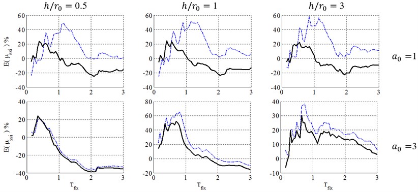
Fig. 4Ductility demand of soil-structure system, resulted from NSPs, for structural ductility of 4 and embedment ratio of 0.5. (-∙-∙-∙- Coefficient method, ––– Equivalent linearization method)
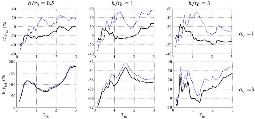
As demonstrated in Fig. 3, in the case of surface foundation (0), using Equivalent Linearization method leads to conservative results at short periods in entire sets of non-dimensional parameters. Indeed, this behavior occurs when the period of the soil-structure system is closer to the predominant period of the site. However, in Coefficient method, the conservative results seems to be unacceptable and occurs at different period ranges for each set of , and .
In other words, these figures indicate that the Equivalent Linearization method leads to conservative results at short periods and almost appropriate results at other spectral parts, but the Coefficient method leads to unacceptably conservative results in most ranges of periods. Also using these methods leads to un-conservative results in some ranges of periods, especially in the case of low-rise buildings (0.5). So, caution should be taken when these NSPs are used for practical systems, for example, low-rise buildings in most spectral period ranges.
For the case of embedded foundation, both KI and II effects are included in the FEMA-440 [7] procedure. The II effect is estimated using suggested equivalent period and damping ratio as the case of surface foundation, while the KI effect has been introduced through KI reduction factor, applied to elastic response spectra.
Fig. 5Ductility demand of soil-structure system, resulted from NSPs, for structural ductility of 4 and embedment ratio of 1. (-∙-∙-∙- Coefficient method, ––– Equivalent linearization method)
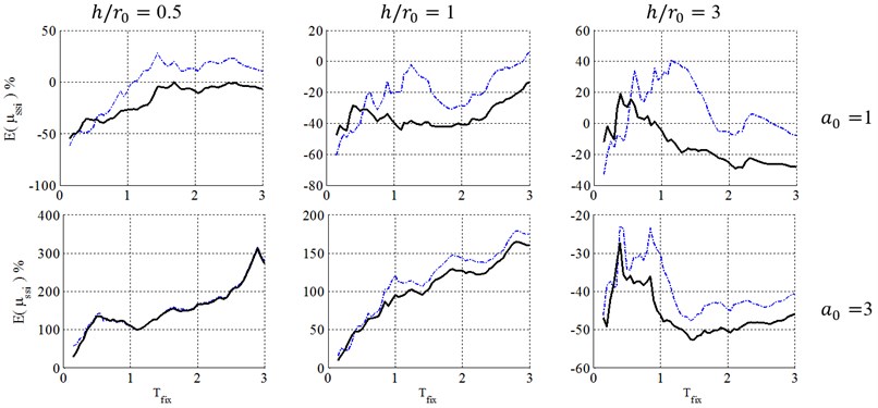
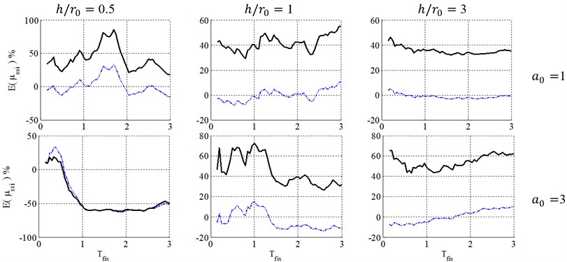
Fig. 6Ductility demand of soil-structure system, resulted from NSPs, for structural ductility of 4 and embedment ratio of 1.5. (-∙-∙-∙- Coefficient method, ––– Equivalent linearization method)
As mentioned in Section 2.2, KI results in a two-component excitation called FIM, while the original FFM has just one horizontal component. Generally, the amplitude of the horizontal component of FIM is less than that of the FFM and their difference becomes larger by increasing the embedment ratio. However, the amplitude of the additional rocking component of FIM starts from zero in case of surface foundation and increases for deeper embedded foundations.
On the other hand, the rocking component produces larger acceleration input on the mass of super-structure, leading to more severe structural response. Consequently, the rocking component of FIM, which is ignored in FEMA-440 [7] procedure, may play an important role to increase seismic demands, especially for tall and slender structures with deep embedded foundation.
The horizontal FFM, , is plotted in comparison with the combined effect of horizontal and rocking components of FIM, , for Imperial-Valley record in Fig. 7. This is done for a soil-structure system with 1.5, 3, 3 and 20. This figure indicates that the effective excitation, resulting from FIM in this extreme condition, is more severe than the FFM excitation. As a case in point, the PGA in the effective excitation is about 0.45 g, which is greater than 0.23 g, the PGA of the original FFM.
Fig. 7Comparing acceleration time history of FFM and combination of horizontal and rocking components of FIM for a soil-structure system with e/r0= 1.5, h/r0= 3, a0= 3 and ωfix= 20. (––– u¨f, - - - - u¨g+h+eϕ¨g)
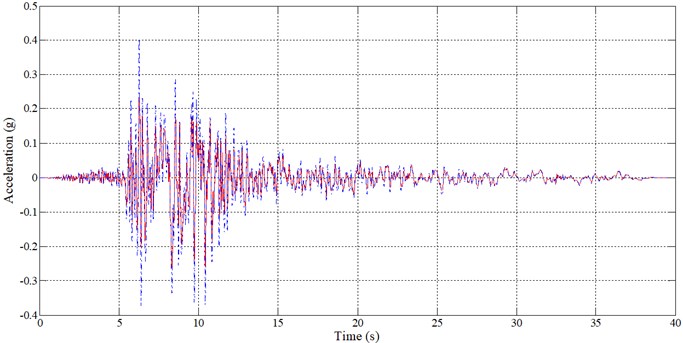
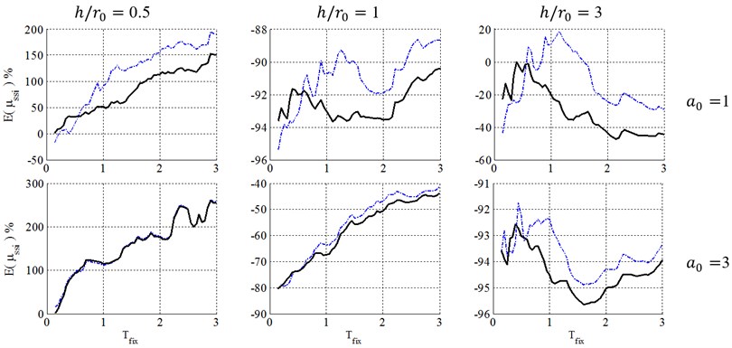
Fig. 8Ductility demand of soil-structure system, resulted from NDA, for structural ductility of 2 and surface foundation. (-∙-∙-∙- Elastic damping, ––– FEMA-440 damping)
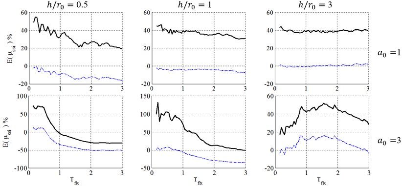
Fig. 9Ductility demand of soil-structure system, resulted from NDA, for structural ductility of 4 and surface foundation. (-∙-∙-∙- Elastic damping, ––– FEMA-440 damping)
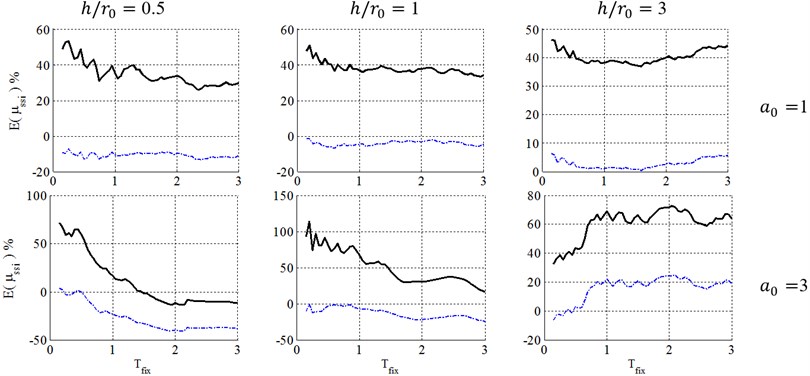
Fig. 10Ductility demand of soil-structure system, resulted from NDA, for structural ductility of 6 surface foundation. (-∙-∙-∙- Elastic damping, ––– FEMA-440 damping)
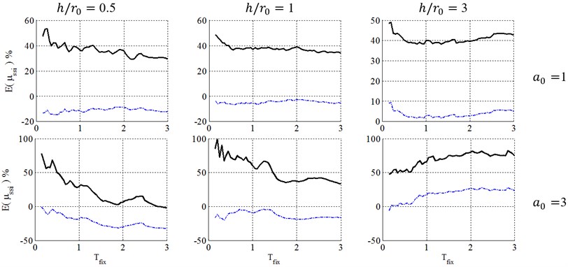
Consequently, as seen in Figs. 4 to 6, for squat structures (0.5 and 1), where inclusion of KI effect generally reduces the flexible-base ductility especially in case of , the FEMA-440 [7] reduction factor can model KI effect and errors caused by FEMA-440 [7] KI effect definition is negligible. For slender structures with , however, the importance of KI effect depends on the embedment ratio. For shallow foundations (0.5), errors caused by FEMA-440 [7] KI effect definition is negligible. In contrast, by increasing the embedment ratio, KI affects the ductility demand more considerably, leading to a significant effect for 1 and 1.5 and increase ductility demands contrary to squat structures. In other words, the FIM is considered as a more severe input motion than the original FFM in such cases. So, using reduction factor of FEMA-440[7] leads to unacceptable negative errors and un-conservative results.
Consequently, the FEMA-440 [7] reduction factor can properly represent KI effect in the case of low-rise building (0.5 and 1) with shallow foundations (). However, in the case of slender structures (), KI acts quite differently and using FEMA-440 [7] definition is almost acceptable for 0.5, but causes unacceptably un-conservative results for deep embedded foundation with 1 and 1.5.
Fig. 11Ductility demand of soil-structure system, resulted from NDA, for structural ductility of 4 and embedment ratio of 0.5. (-∙-∙-∙- Elastic damping, ––– FEMA-440 damping)

Fig. 12Ductility demand of soil-structure system, resulted from NDA, for structural ductility of 4 and embedment ratio of 1. (-∙-∙-∙- Elastic damping, ––– FEMA-440 damping)
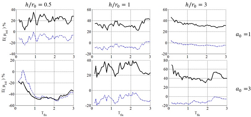
6.2. Damping definition of equivalent replacement oscillator
Figs. 8 to 13 present a comparison between caused by elastic and inelastic damping definitions of equivalent replacement oscillator in elasto-plastic structures with post yielding stiffness ratio, , ductility demands of 2, 4 and 6 with surface and embedded foundations located on site class E. As illustrated, the inelastic damping definition proposed by the FEMA-440 [7] results in larger errors than elastic damping definition that may cause very conservative results. But because of its negative errors, using elastic damping definition may cause unacceptable results in engineering concepts, especially in low-rise buildings (0.5 and 1). The results also demonstrate that with increase of the embedment ratio, and slenderness ratio, and decrease of ductility demand, , the errors caused by FEMA-440 [7] damping definition decrease and therefore this definition becomes more acceptable. This phenomenon can be explained in the way that lower ductility ratios represent a system where the structure doesn’t undergo remarkable nonlinear displacement and therefore it is reasonable to assume that the structure behaves elastic in the foundation damping calculation and errors caused by this simplification decrease. In addition, slender structures gain less radiation damping from the soil and therefore their corresponding response is not as sensitive as response of structures with low slenderness ratios to the type of damping definition.
Fig. 13Ductility demand of soil-structure system, resulted from NDA, for structural ductility of 4 and embedment ratio of 1.5. (-∙-∙-∙- Elastic damping, ––– FEMA-440 damping)
This is noteworthy that equivalent damping ratio of soil-structure system is consisted of the foundation damping, indeed the classic 5 % damping ratio of fixed-base structures. But an approximate equation is introduced in the FEMA-440 [7] procedure to determine the response of the equivalent damping from the response of the existing 5 % damping ratio elastic spectra. But in current study, a direct elastic time history analysis is carried out to determine these results, which restricts the errors caused by that approximate equation and concentrates errors on SSI effect. So, the real errors caused by FEMA-440 [7] procedure to obtain response of soil-structure systems may be more than that are shown in Figs. 3 to 13.
7. Conclusions
Results of this study are prepared in two parts. In the first part, the accuracy of nonlinear static procedures to analyze soil-structure systems, that proposed by FEMA-440 [7] regulations, are investigated. The investigation found that the Equivalent Linearization method provides conservative results at short structural periods and acceptable results for medium and long structural periods. However, the Coefficient Method does not achieve proper results and greatly overestimates when the period of the soil-structure system is close to the predominant period of the site. Also, using these methods leads to un-conservative results in some range of periods, especially in the case of low-rise buildings.
Indeed, in the case of embedded foundation, the FEMA-440 [7] response reduction factor can properly represent KI effect in the case of low-rise building with shallow foundations. However, in the case of slender structures, KI acts quite differently and using FEMA-440 [7] definition is almost acceptable for 0.5, but causes unacceptably un-conservative results for the case of 1 and 1.5. This phenomenon is because of the effect of rocking component of FIM, which is ignored in FEMA-440 [7] procedure, may produce larger acceleration input and leads to more severe structural response in the case of high-rise building with deep foundations.
Therefore, it is recommended to define equations and coefficients of current nonlinear static procedures as a function of soil-structure systems’ key parameters to include SSI effects and modify current nonlinear static procedures to analyze soil-structure systems using these new equations and coefficients.
In the second part, a comparison is performed between FEMA-440 [7] inelastic equivalent damping ratio and common elastic damping ratio definitions to investigate the accuracy of seismic ductility demands resulted from these equivalent replacement oscillators. It is concluded that the inelastic damping definition proposed by the FEMA-440 [16] results in larger errors than elastic damping definition that may cause very conservative results. But because of its negative errors, using elastic damping definition may cause unacceptably un-conservative results in engineering concepts, especially in low-rise buildings.
References
-
Pre-standard and Commentary for the Seismic Rehabilitation of Buildings. FEMA-356, Federal Emergency Management Agency, 2000.
-
Seismic Evaluation and Retrofit of Concrete Buildings. ATC-40, Applied Technology Council, 1996.
-
Bosco M., Ferrara G. A. F., Ghersi A., Marino E. M., Paolo Rossi P. Predicting displacement demand of multi-story asymmetric buildings by nonlinear static analysis and corrective eccentricities. Engineering Structures, Vol. 99, Issue 15, 2015, p. 313-387.
-
Mazza F. Modelling and nonlinear static analysis of reinforced concrete framed buildings irregular in plan. Engineering Structures, Vol. 80, Issue 1, 2014, p. 98-108.
-
Wan G., Zhang D., Robert B., Fleischman R. B., Naito C. J. A coupled connector element for nonlinear static pushover analysis of precast concrete diaphragms. Engineering Structures, Vol. 86, Issue 1, 2015, p. 58-71.
-
Foraboschi P., Vanin A. Non-linear static analysis of masonry buildings based on a strut-and-tie modeling. Engineering Structures, Vol. 55, 2013, p. 44-58.
-
Improvement of Nonlinear Static Seismic Procedures. ATC-55 Draft, FEMA-440, Washington, 2005.
-
Meek J. W., Wolf J. P. Cone models for embedded foundation. Journal of Geotechnical Engineering Division (ASCE), Vol. 120, Issue 1, 1994, p. 60-80.
-
Tentative Provisions for the Development of Seismic Regulation for Buildings. ATC3-06, Applied Technology Council, 1978.
-
NEHRP Recommended Provisions for Seismic Regulations for New Buildings and Other Structures. FEMA-450, BSSC, Washington, 2003.
-
Veletsos A. S., Meek J. W. Dynamic behavior building-foundation systems. Earthquake Engineering and Structural Dynamic, Vol. 34, 1974, p. 121-138.
-
Veletsos A. S., Nair V. V. D. Seismic interaction of soil on hysteretic foundation. Journal of Structural Division (ASCE), Vol. 101, 1975, p. 109-129.
-
Wolf J. P. Dynamic Soil-structure Interaction. Prentice Hall, New Jersey, 1985.
-
Aviles J., Perez-Rocha L. E. Diagrams of effective periods and damping of soil-structure systems. Journal of Geotechnical and Geo-environmental Engineering, Vol. 125, 1999, p. 711-715.
-
Bielak J. Dynamic response of non-linear building-foundation systems. Earthquake Engineering and Structural Dynamic, Vol. 6, 1978, p. 17-30.
-
Aviles J., Perez-Rocha L. E. Soil-structure interaction in yielding systems. Earthquake Engineering and Structural Dynamic, Vol. 32, 2003, p. 1749-1771.
-
Aviles J., Perez-Rocha L. E. Design concepts for yielding structures on flexible foundation. Engineering Structure, Vol. 27, 2005, p. 443-454.
-
Ghannad M. A., Ahmadnia A. The effect of soil-structure interaction on inelastic structural demands. European Earthquake Engineering, Vol. 1, 2006, p. 23-35.
-
Ghannad M. A., Jahankhah H. Site-dependent strength reduction factors for soil-structure systems. Soil Dynamics and Earthquake Engineering, Vol. 27, 2007, p. 99-110.
-
Eser M., Aydemir C. The effect of soil-structure interaction on inelastic displacement ratio of structures. Structural Engineering and Mechanics, Vol. 39, Issue 5, 2011, p. 683-701.
-
Eser M., Aydemir C., Ekiz I. Inelastic displacement ratios for structures with foundation flexibility. KSCE Journal of Civil Engineering, Vol. 16, Issue 1, 2011, p. 155-162.
-
Lin Y. Y., Miranda E. Kinematic soil-structure interaction effects on maximum inelastic displacement demands of SDOF systems. Bulletin of Earthquake Engineering, Vol. 6, Issue 2, 2008, p. 241-259.
-
Stewart J. P., Comartin C., Moehle J. P. Implementation of soil-structure interaction models in performance based design procedures. Proceedings of the Third UJNR Workshop on Soil-Structure Interaction, Menlo Park, CA, USA, 2004.
-
Mahsuli M., Ghannad M. A. The effect of foundation embedment on inelastic response of structures. Earthquake Engineering and Structural Dynamics, Vol. 38, 2009, p. 423-437.
-
Madani B., Behnamfar F., Tajmir Riahi H. Dynamic response of structures subjected to pounding and structure-soil structure interaction. Soil Dynamics and Earthquake Engineering, Vol. 78, 2015, p. 46-60.
-
Durmuş A., Livaoglu R. A simplified 3 D.O.F. model of A FEM model for seismic analysis of a silo containing elastic material accounting for soil-structure interaction. Soil Dynamics and Earthquake Engineering, Vol. 77, 2015, p. 1-14.
-
Galvín P., Romero A. A MATLAB toolbox for soil-structure interaction analysis with finite and boundary elements. Soil Dynamics and Earthquake Engineering, Vol. 57, 2014, p. 10-14.
-
Medina C., Aznárez J. J., Padrón L. A., Maeso O. Effects of soil-structure interaction on the dynamic properties and seismic response of piled structures. Soil Dynamics and Earthquake Engineering, Vol. 53, 2013, p. 160-175.
-
Wolf J. P. Foundation Vibration Analysis using Simple Physical Models. Prentice-Hall, Englewood Cliffs, NJ, 1994.
-
Kramer S. L. Geotechnical Earthquake Engineering. Prentice-Hall, Englewood Cliffs, 1996.
-
Veletsos A. S., Dynamic of structure-foundation systems. Structural and Geotechnical Mechanics, 1977, p. 333-361.
-
Ghannad M. A. A Study on the Effect of Soil-Structure Interaction on the Dynamic Properties of Structures Using Simplified Methods. Ph.D. Thesis. Nagoya University, Japan, 1998.
-
Behmanesh I., Khoshnudian F. Effect of soil-structure-interaction on inelastic displacement ratios of existing structures. The 14th World Conference on Earthquake Engineering, Beijing, China, 2008.
Cited by
About this article

