Abstract
Masonry infills are largely used in RC structures for various purposes, and in seismic zones, they are also preferred for providing earthquake resistant systems. However, due to the rigid connection between infills and RC frames, these systems are vulnerable when large deformations are demanded. Cyclic loads that are occurring during seismic excitations cause stress concentration level to increase, particularly in frame-infill contact zones. As a result of stress increment, infill panels get weaker in terms of both in-plane and out-of-plane resistance. These drawbacks cause loss of lives and properties, thus affecting governments and societies adversely. In order to overcome this obstacle, an innovative solution is proposed which uses flexible polymers (Polyurethane PM) as joint elements for protecting the structural elements. The research is focused on numerical analyses of three types of frames with masonry infills, which are excited through both in-plane and out-of-plane directions by different earthquake records. Infill walls are connected to the frames in three manners: stiffly (classical approach), with flexible joints at 3-boundaries and with flexible joints at 4-boundaries. Differences in calculated stress distribution as well as some other linear and non-linear results are presented and discussed. The primary results give promising outcomes that this new method might be used in seismic zones for protecting structures.
1. Introduction
Masonry infills are extensively used particularly in RC structures. Despite its popularity in construction sector, there are still some major drawbacks that are waiting to be solved regarding their strength and durability features under seismic loads. These concerns are emerged mainly due to the brittle characteristics of masonry materials such as clay bricks and concrete blocks. These infill walls might be very fragile even under low density seismic loads and cracks can be observed easily on their visible faces. In many instances, total collapse of the infills are also observed due to either in-plane or out-of-plane strength loss. On the other hand, if strong bricks are used between RC frames, then another risk occurs that might lead frame elements to get damage due to concrete crushing especially in corner zones, where beams and columns are connecting. These mentioned damage types are caused mostly because of the interaction effects, which occur in the boundary zones between RC elements and masonry infills. This very crucial aspect was investigated lastly with various solutions [1-6].
In this study, an innovative solution that is being developed at Cracow University of Technology (CUT) for over a decade is proposed in order to mitigate seismic hazard on above mentioned cases. The principle is based on using a polymer material called as Polyurethane PM, which has hyper-elastic features that allows high ductility to be used as flexible joints. Many studies are already done regarding the usage of this specific material as Polymer Flexible Joints (PFJ) in structures [7-10]. Within the scope of this study, three different joint connection types are investigated. The first type is a classical approach as connecting an infill to an RC frame stiffly. The second and third types are assumed to represent PFJ usage in existing (old) and to-be-built (new) buildings respectively. Since old buildings already have existing walls, implementing flexible joints around the three boundaries of infills are easier and more economical solution rather than removing an entire wall and implementing joints on all around masonry-frame interfaces. Therefore, second type has flexible joints connected at 3 boundaries except bottom of the walls. The third type, similar to the second one, has PFJ around the wall perimeter. However, because it is chosen to represent an implementation in new buildings, 4 sides of the walls have PFJ for this type of frame. In Fig. 1, these three types of frames are presented.
Fig. 1Analyzed infill structures with masonry walls connected to RC frames with: a) stiff connection around the wall, b) flexible PM connection at 3 boundaries, c) flexible PM connection at 4 boundaries
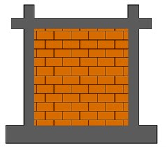
a)
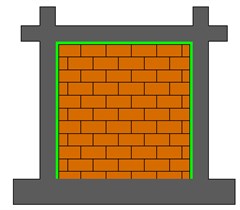
b)
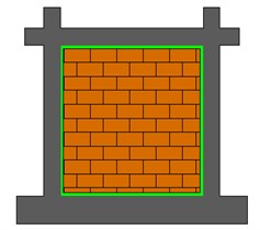
c)
The frames are originally designed for shaking table tests at Slovenian National Building and Civil Engineering Institute (ZAG) in Ljubljana. However, some modifications are made in the scope of this study and then numerical analyses are performed. First, natural frequencies are found with the corresponding mode shapes using material elastic properties. Following that, simplified non-linear analyses are conducted in order to determine real-like and post-elastic behavior. Comparison between linear and non-linear approach is provided once the analyses are completed. Finally, other outcomes are presented such as displacements, stress maps etc. and the results are discussed.
2. Description of the frames
All types of frames have square shape infill walls with 220×220 cm2 dimensions. Masonry infills consist of Polish Bonarka bricks with dimensions 25×12×6.5 cm3. These bricks are arranged in an order that 25 cm thickness is provided for overall masonry unit, thus a strong and thick-type masonry is created. Three different flexible joint thicknesses are tested, namely 1 cm, 2 cm and 3 cm in order to check optimum dimension for the joints.
Frames have concrete class C30/37 and B500C reinforcement steel [11]. Masonry is created by Polish Bonarka bricks. Mean compression strength of the bricks determined as 23.3 MPa previously [12]. Elastic features of the masonry are calculated according to Eurocode-6 (EC6) [13] and Polyurethane PM values are taken from previous studies [14, 15]. Material properties of the elements are presented in Table 1.
Table 1Elastic material properties
Masonry properties | Polyurethane PM properties | |||||
(MPa) | (MPa) | (MPa) | (MPa) | |||
23.3 | 12050 | 4820 | 0.25 | 4.5 | 0.47 | 0.5-1.5 |
3. Description of the numerical models
Numerical models are created with FEM program SAP2000 [16]. Linear analyses are done by using eight-node hexahedral solid elements, whereas non-linear behaviors are investigated by two-dimensional shells and one-dimensional bars for masonries and frame members (column, beam) respectively, see Fig. 2. Non-linear properties are provided for masonries and PJFs with multi-layer shell model [17]. On the other hand, frame non-linearity is simulated by plastic hinges with half-section height hinge lengths lumped at the both ends of bars. Rigid links are used for connecting frames to the shell elements. Masonry infills are created by continuum material model approach, thus no joint-brick-friction surface interaction was considered. In addition, material non-linearity for masonry and PFJ is determined according to the previous studies [14, 18]. These properties are presented in Fig. 3.
Fig. 2Element types: a) shell elements, b) solid elements [16]
![Element types: a) shell elements, b) solid elements [16]](https://static-01.extrica.com/articles/20449/20449-img4.jpg)
a)
![Element types: a) shell elements, b) solid elements [16]](https://static-01.extrica.com/articles/20449/20449-img5.jpg)
b)
Fig. 3Nonlinear material properties: a) masonry, b) polyurethane PM
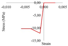
a)
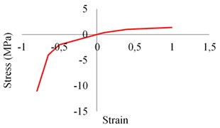
b)
4. Seismic records used for the analyses
Two different seismic records are used for the analyses with details given in Table 2. The records are used for both in-plane and out-of-plane excitations. Time-acceleration graph of the records are also shown in Fig. 4. Additionally, to the seismic lateral loads, an extra 1.0 ton weight was distributed equally on the top of columns as 0.5 ton on each is implemented.
Table 2Details of the seismic records
Earthquake name | Date | Depth (km) | Magnitude () | PGA (g) |
El Centro | 18.05.1940 | 16 | 6.9 | 0.32 |
Petrolia | 25.04.1992 | 11 | 7.2 | 0.59 |
5. Results of the analyses
Linear analyses result of the frames are given for natural vibration frequencies in Table 3. Typical in-plane and out-of-plane mode shapes are also shown in Fig. 5. Stiff connection has the highest frequency value as expected, whereas 4 boundaries PFJ frames have the lowest ones due to the flexible joint’s presence around the entire perimeter of walls. This influence is more significant for in-plain modes.
Fig. 4Time-acceleration graph of the earthquake records
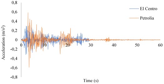
Table 3Modal frequencies of the frames
Frame type | PFJ thickness | 1st mode frequency (out-of-plane) – Hz | 1st mode frequency (in-plane) – Hz |
Stiff | – | 14.95 | 105.10 |
3 Boundaries PFJ | 1 cm | 14.88 | 77.97 |
2 cm | 14.86 | 70.40 | |
3 cm | 14.85 | 65.00 | |
4 Boundaries PFJ | 1 cm | 10.25 | 45.52 |
2 cm | 9.71 | 36.76 | |
3 cm | 9.47 | 32.34 |
Fig. 5Typical 1st mode shapes of the frames: out-of-plane (left) and in-plane (right)
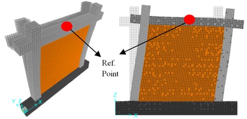
Nonlinear analyses are performed both for in-plane and out-of-plane directions by using seismic records presented in Table 2. The results are investigated in terms of displacement values of the reference point and Von Misses stress maps under different excitations. The maximum displacements are given in Table 4 and the stress maps are shown in Fig. 6-11. Stress maps are given only for Petrolia excitation and for three types of frames, which are Stiff, 3-Boundaries PFJ with 2 cm joint thickness and 4-Boundaries PFJ with 2 cm joint thickness.
Table 4Maximum displacement values of the frames
– | – | El Centro (mm) | Petrolia (mm) | ||
Frame type | PFJ thickness | In-plane | Out-of-plane | In-plane | Out-of-plane |
Stiff | – | 0.01 | 1.33 | 0.02 | 1.83 |
3 Boundaries PFJ | 1 cm | 0.03 | 1.80 | 0.06 | 2.39 |
2 cm | 0.04 | 1.95 | 0.08 | 2.47 | |
3 cm | 0.05 | 2.02 | 0.10 | 2.70 | |
4 Boundaries PFJ | 1 cm | 0.11 | 2.41 | 0.22 | 3.36 |
2 cm | 0.20 | 2.52 | 0.36 | 3.97 | |
3 cm | 0.28 | 2.51 | 0.49 | 4.22 | |
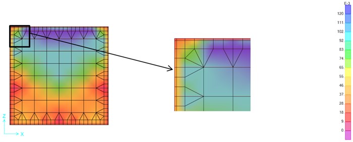
Fig. 6Stress map of the Petrolia in-plane excitation – stiff connection (MPa)
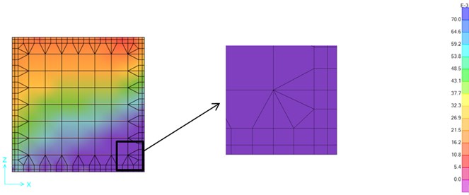
Fig. 7Stress map of the Petrolia in-plane excitation – 3-Boundaries 2 cm-PFJ (MPa)
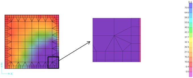
Fig. 8Stress map of the Petrolia in-plane excitation – 4-Boundaries 2 cm-PFJ (MPa)
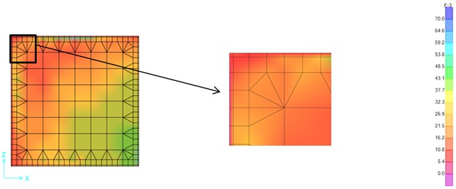
Fig. 9Stress map of the Petrolia out-of-plane excitation – stiff connection (MPa)
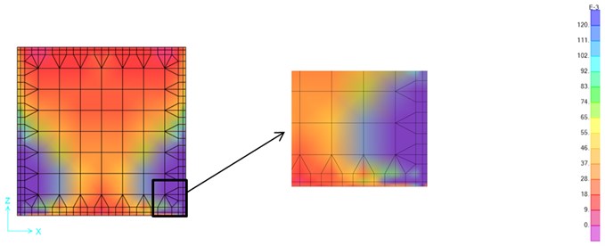
Fig. 10Stress map of the Petrolia out-of-plane excitation – 3-Boundaries 2 cm-PFJ (MPa)
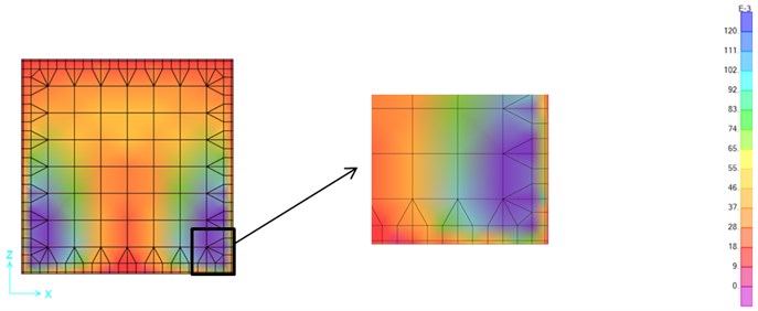
Fig. 11Stress map of the Petrolia out-of-plane excitation – 4-Boundaries 2 cm-PFJ (MPa)
6. Conclusions
Several numerical analyses are performed in order to understand influence of a newly developed flexible joint material in RC frames with infill walls. The results are given below:
1) Stiff connection frame has the highest frequency and the lowest displacement values, thus it tends to behave the stiffest in comparison with the other frame types. This is an expected outcome, since no deformable joint exists for this type. On the other hand, while the PJF thickness rises, natural frequencies get lower particularly for the in-plane direction.
2) Implementation of the flexible joints leads the frame to be more ductile both for in-plane and out-of-plane directions. Providing ductile structures is a very convenient and important issue for earthquake resistant building designing. Therefore, these results are promising.
3) Stress maps also show the effectiveness of flexible joints of 2 cm thickness, where substantial stress loss around the boundary zones of PFJ and masonry can be observed. The stress loss reaches up to 5 and 3 times for in-plane and out-of-plane excitations, respectively. Both 3-Boundaries and 4-Boundaries implementations seem to be effective, whereas stress distributions exhibit some specific differences particularly due to the bottom part of walls, where 3-Boundaries type is restrained by stiff connection and 4-Boundaries type has flexible joints.
Despite the simplifications such as continuum material model and simplified nonlinear modeling technique for masonry walls, the results still seem consistent and realistic. Implementation of flexible joints in real structures can decrease or totally prevent destructive seismic effects on masonry walls in RC buildings. Further studies will focus on more detailed numerical solutions as well as laboratory tests.
References
-
Mohammadi M., Akrami V., Mohammadi Ghazi R. Methods to improve infilled frame ductility. Journal of Structural Engineering, Vol. 137, Issue 6, 2011, p. 646-653.
-
Misir I. S., Ozcelik O., Girgin S. C., Kahraman S. Experimental work on seismic behavior of various types of masonry infilled RC frames. Structural Engineering and Mechanics, Vol. 44, Issue 6, 2012, p. 763-774.
-
Preti M., Bettini N., Plizzari G. Infill walls with sliding joints to limit infill-frame seismic interaction: large scale experimental test. Journal of Earthquake Engineering, Vol. 16, Issue 1, 2012, p. 125-141.
-
Markulak D., Radic I., Sigmund V. Cyclic testing of single bay steel frames with various types of masonry infill. Engineering Structures, Vol. 51, 2013, p. 267-277.
-
Johnson H., Watson C., Pampanin S., Palermo A. Shake table testing of an integrated low damage building system. Proceedings of the 2nd European Conference on Earthquake Engineering and Seismology, Istanbul, Turkey, 2014.
-
Vailati M., Monti G. Earthquake-Resistant and Thermo-Insulating Infill Panel with Recycled-Plastic Joints. Earthquakes and Their Impact on Society, Springer Natural Hazards, 2016, p. 417-432.
-
Kwiecień A. Polymer Flexible Joints in Masonry and Concrete Structures. Monography No. 414, Kraków, 2012, (in Polish).
-
Kisiel P. The stiffness and bearing capacity of polymer flexible joint under shear load. Procedia Engineering, Vol. 108, 2015, p. 496-503.
-
Kwiecień A., Gams M., Rousakis T., Viskovic A., Korelc J. Validation of a new hyperviscoelastic model for deformable polymers used for joints between RC frames and masonry infills. Engineering Transactions, Vol. 65, Issue 1, 2017, p. 113-121.
-
Kwiecień A., Gams M., Viskovic A., Kisiel P., Korelc J., Rousakis T. Use of polymer flexible joint between RC frames and masonry infills for improved seismic performance. SMAR, Zurich, 2017.
-
Eurocode 2: Design of Concrete Structures – Part 1-1: General Rules and Rules for Buildings. European Committee for Standardization, Brussels, 2004.
-
Kwiecień A., Kuboń P., Zając B. Numerical Analysis of Cracked Masonry Building Excited by an Earthquake After Repair Using Polymer Flexible Joint. Recent Advances in Civil Engineering: Structural Mechanics. Kraków, 2015, p. 63-79.
-
Eurocode 6: Design of Masonry Structures – Part 1-1: General Rules for Reinforced and Unreinforced Masonry Structures. European Committee for Standardization, Brussels, 2005.
-
Kisiel P. Model Approach for Polymer Flexible Joints in Precast Elements Joints of Concrete Pavements. Ph.D. Thesis, CUT, Cracow, 2018.
-
Gams M., Kwiecień A., Korelc J., Rousakis T.,Viskovic A. Modelling of deformable polymer to be used for joints between infill masonry walls and R.C. frames. Procedia Engineering, Vol. 193, 2017, p. 455-461.
-
SAP2000 v15.2.1. CSI Analysis Reference Manual, Berkeley, CA., 2005.
-
Miao Z. W., Lu X. Z., Jiang J. J., Ye L. P. Nonlinear FE model for RC shear walls based on multi-layer shell element and microplane constitutive model. Computational Methods in Engineering and Science, Sanya, Hainan, China, 2006.
-
Cavaleri L., Di Trapani F. Prediction of the additional shear action on frame members due to infills. Bulletin of Earthquake Engineering, Vol. 13, Issue 5, 2015, p. 1425-1454.
Cited by
About this article

