Abstract
The study of flexible intelligent hand prosthesis has important practical significance for handicapped people. Aiming at the grasping force control of flexible hand prosthesis, this paper draws lessons from the anatomical structure design of human hand, and proposes a fingertip grasping force control method based on linear tension feedback. The control strategy can realize the stable control of fingertip grasping force. The static mechanical model of finger is established, and the mathematical relationship of fingertip contact force calculation in static state is obtained. Then a friction compensation method is proposed. The experimental results show that the fitting value of the friction moment of the lasso matches well with the test value, and the error after friction compensation is obviously reduced.
Highlights
- Draw lessons from the anatomical structure design of human hand
- Propose a fingertip grasping force control method based on linear tension feedback
- The control strategy can realize the stable control of fingertip grasping force
1. Introduction
In recent years, the number of stroke patients has increased year by year, for example, more than 2.7 million new cases of cerebrovascular disease occur every year in China, about 1.3 million people die of cerebrovascular diseases every year. And among all stroke survivors, about 80 % of people suffer from different degrees of hand and hand motor dysfunction [1, 2]. These patients are unable to perform the simplest daily activities, such as grab a glass of water to drink, take a spoon to eat, etc. At the same time, the recovery of hand motor function is slower than that of other body parts. As a result, the patient’s daily life needs the help of others for a long time, it causes serious economic and living burden to the family. However, intelligent hand prosthesis is currently recognized as a method to help patients recover limb motor function [3, 4]. Through the help of intelligent hand prosthesis, to some extent, it can assist or replace doctors to carry out continuous and effective rehabilitation training, which plays an important role in restoring limb motor function of patients. At the same time, it can alleviate the complications caused by long-term physical disability.
At present, intelligent hand prosthesis are mainly classified into two categories in terms of their structural properties [5], including rigid type and flexible type. The study of rigid intelligent hand prosthesis was earlier, some of the research results can well realize the rehabilitation training of patients. But they also have insurmountable shortcomings: (1) The structure is complex and the volume is large, so it is difficult to be used in daily life; (2) The rigid structure can’t fit the hand perfectly, and the patients are vulnerable to secondary injury in the use process; (3) The cost is too high for many ordinary families to bear and popularize. However, in recent years, flexible intelligent hand prosthesis just makes up for the deficiency of rigid type. In this paper, the capability of performance analysis and experiment is studied to provide basis for optimum design.
2. Working principle of flexible intelligent hand prosthesis
Generally, the bionic design of flexible intelligent hand prosthesis is based on human anatomical structure. The fingertip contact force control method is proposed by linear tension feedback. In order to achieve this goal reasonably, the finger static mechanical model of flexible hand prosthesis should be established firstly. Then the corresponding compensation schemes are put forward for the friction loss in the process of cable drive. Finally, the fingertip contact force control can be realized. Experiments need to be carried out to validate the patients with hand loss of motor function.
The structure of the hand is the result of hundreds of millions of years of biological evolution. Therefore, the mode of action of energy, efficiency and force has been continuously optimized with imitating and learning. So, the flexible intelligent hand prosthesis should be designed based on the hand structure with using bionic design, which can make the movement of flexible intelligent hand prosthesis more in line with the natural movement track of human hands. The human fingers consist of bones, joints and ligaments attached to their surfaces. These tissues are driven by muscles and tendons. Tendons pass through the annular pulley structure and connect muscles and phalanges. Each finger consists of three joints, and will cause flexion and extension by transferring muscle strength.
The normal functioning of the tendon at the finger mainly depends on three parts: the stop point, the trochlea and the abdomen of muscle. The stop point is the position where the tendon connects to the phalanx, which provides the focus for the tendon. The trochlea has the function of restraining the flexor tendon and providing a mechanical fulcrum for the tendon. The abdomen of muscle drives tendon movement through contraction, which drives finger bone movement connected with tendon. Hand grabbing can be divided into precision grip and power grip [6].
In the “pinch” motion mode, the object is clamped between the flexor surface of the finger and the flexor surface of the thumb opposite to it. In the “grip” motion mode, the object is held in a wrap between the curved fingers and the palm of the hand. These two modes basically cover the whole activity type of the hands. When the “pinch” movement mode is performed, most of the driving forces are transmitted through the flexor tendon of the superficial finger. Based on the principles of finger anatomy, the flexible intelligent hand prosthesis that designed in this paper is simulated by using two tension lines. The wire groove attached to the flexible hand prosthesis acts as the finger pulley structure, transfer tendon force to phalanges and prevent tendons from deviating from their path during movement. In addition, the flexible hand prosthesis replaces the extensor tendon with the “radial” wiring.
In a multi-fingered manipulator, the differential mechanism is used to achieve under-actuation to achieve good adaptability to the target object [7]. In this paper, the under actuated mechanism of the manipulator is applied to the driving of the index and middle fingers of flexible hand prosthesis. The pull line connected with the DC motor realizes the finger bending motion by pulling the pulley. The pulling stroke and the tension of the line can be evenly distributed to two fingers. Therefore, the thumb is fixed in the grasping gesture with the largest operating space. In order to reduce the weight directly acting on the patient’s hand, the main part of the flexible hand prosthesis is made of polyester and polymer. The transmission part is driven by a sling which allows the separation of the end-effector and the driving side. Ultimately, the weight of flexible hand prosthesis is almost the same as that of ordinary type.
3. Design of intelligent control scheme
3.1. Feasibility analysis
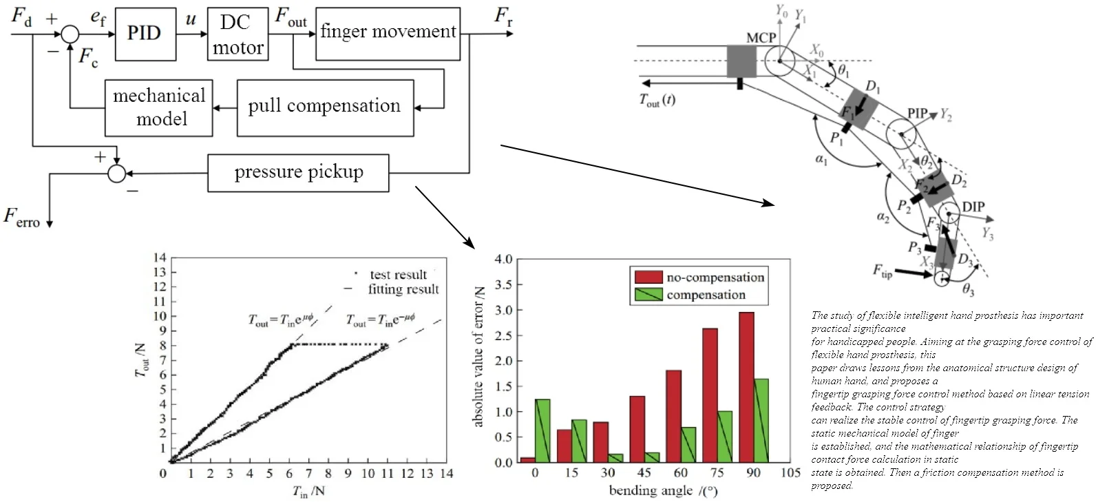
In order to control the grasping force at fingertips, a control method based on linear tension feedback [8] is proposed. Its core idea is to calculate fingertip grasping force by measuring the line tension at the entrance side of the lasso. Firstly, the non-linear friction loss in the cable drive is compensated, and the line tension at the exit side of the lasso is obtained. Then the fingertip grasping force is further calculated by the static mechanical model of the finger. Finally, the grasping force is effectively controlled by the control method proposed in this paper. The specific control block diagram is shown in Fig. 1.
In this paper, incremental PID control is adopted for tension control. In Fig. 1, is the desired contact force between fingertips and objects. is the estimated contact force between fingertips and objects. is the actual contact force between fingertips and objects. is force deviation. is the tension of the side line at the entrance of the lasso. is the actual contact force deviation between fingertips and objects. is motor drive input. The line tension measured at the entrance side of the sling is used to calculate the fingertip contact force by friction compensation and static mechanical model of the finger. Make it track the desired contact force between fingertips and objects. The contact force of the fingertip measured by the thin film pressure sensor in the control block diagram does not act as feedback on the closed-loop control of the system. It verifies the feasibility of the finger static mechanical model and the friction compensation scheme by calculating the error between the finger static mechanical model and the expected contact force.
Fig. 1The specific control block diagram
3.2. Structure and force analysis
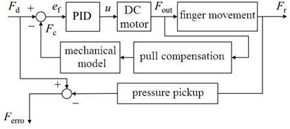
In order to obtain the relationship between the tension of the side line at the exit of the lasso and the contact force between the fingertips, a static mechanical model of a single finger was established as shown in Fig. 2. The following assumptions are used in modeling: (1) Every joint is a pure rotating joint. (2) The friction between the tension line and the conductor groove is neglected. (3) The position of the conductor groove relative to the finger does not move under the action of force. Based on the above assumptions, a single finger can be considered as a three-bar structure. Because the effect of placing wire grooves on both sides of phalanges on phalanges is the same as that of placing wire grooves on the central axis of phalanges. Therefore, it is considered to be placed in the phalanx axis position for modeling.
Fig. 2The static mechanical model of a single finger
In order to facilitate the representation and analysis of static mechanical models, the base coordinate system {, , } is established at the axis of MCP joint of finger. The coordinate systems , , }, {, , } and {, , } were established at the axes of MCP, PIP (proximal interphalangeal joint) and DIP (distal interphalangeal joint), respectively. The origins are located at the axes of MCP, PIP and DIP joints respectively. The coordinate axes of , , and Z3 coincide with the axes of each joint axis, and all -axis directions are perpendicular to the paper facing out. The coordinate axes of , , and point from the current axis to the next axis along the common vertical direction. The coordinate axes of , , and are determined by the right-hand rule. The bending angle of each joint of the finger is described by ( 1, 2, 3). The angle of the tension line passing through the conductor groove ( 1, 2, 3) at the conductor groove is described by . The homogeneous transformation matrix from coordinate system to coordinate system is obtained by Eq. (1) and Eq. (2):
In order to obtain the static mechanical model of the finger, the position usage formula of all conductor grooves in flexible intelligent hand prosthesis can be transformed base on Eq. (3) with coordinate system 0. is the position vector in the coordinate system of the conductor slot. In the base coordinate system 0, the unit vector from conductor groove to conductor groove is calculated by Eq. (4):
Because the pull line indirectly acts on the finger, the resultant force ( 1, 2, 3) of each phalanx is located at the corresponding position of which is on the back of the finger. Therefore, in order to obtain the torque produced by resultant force to the joint, is regarded as the force action point. The interaction torque is shown in Eq. (5):
where represents the blocking torque at the joint.
3.3. Friction compensation
In order to reduce the influence of the change of bowden-cable shape on grasping force control, a physical method is adopted to limit the range of the cumulative bending angle of the cable and to compensate the friction by means of median value. Considering that wheelchairs are necessary for the movement of most patients who have lost the motor function of their hands. Therefore, the driving mechanism of the flexible hand prosthesis can be installed on the back of the wheelchair, fixed part of the lasso on the wheelchair. The change range of in the final patient is between 0°-90° when grasping the target object. For the friction compensation part, the cumulative bending angle of the cable cannot be measured in real time. Therefore, the paper chooses half of the maximum friction loss between 0°-90° to compensate the cumulative bending angle of the lasso. In order to reduce the influence of the shape change of the lasso on the grasping force control, the friction compensation controller is designed to add the friction compensation value to the tension of the side line at the entrance of the cable, to ensure that the tension at the exit of the lasso can follow the expected value well.
3.4. Experimental test and analysis
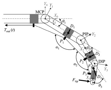
In order to verify the effectiveness of friction compensation through experiments, on the basis of the experimental system, a linear guide with a tension sensor is used to replace the main part of the flexible hand prosthesis for measuring the linear tension at the exit side of the lasso. Aiming at the friction compensation method proposed in this paper, when the cumulative bending angle of the cable is 90°, the friction characteristic curve of the cable is obtained, then the actual friction model is established. During the experiment, the cumulative bending angle of the lasso was fixed at 90°, the relative sliding velocity between rope and casing is set to 0.0042 m/s. The experimental verification results are shown in Fig. 3. As can be seen from the Fig. 3, the experimental results are consistent with the fitting results.
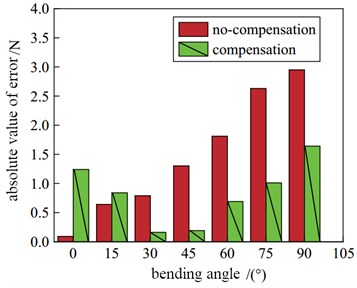
The friction factor of the lasso remains unchanged during the experiment. Change the cumulative bending angle of the lasso. Six groups of angles were selected in the range of the cumulative bending angle of the lasso (as shown in Fig. 4), and the interval between the angles was 15°. For each group of experiments, the experiments were carried out under the condition of friction-free compensation and friction-free compensation respectively. The linear tension at the outlet side of the expected Lasso is set to 10 N. From Fig. 4, it can be seen that the absolute error values of six groups of frictionless compensation and frictional no-compensation during the experiment could be superposed and summed respectively. The sum of the absolute value of force tracking error without friction compensation is 10.21 N. The sum of absolute force tracking error with friction compensation is 5.77 N. The experimental results basically coincide with the integral of the absolute value of the force estimation error. Therefore, the friction compensation experiment proves that the proposed friction compensation method can effectively reduce the force estimation error at the exit side of the bowden-cable.
Fig. 3Verification of friction torque
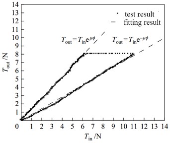
Fig. 4Error comparison at different bending angle
4. Conclusions
Flexible intelligent hand prosthesis is one hotspot and difficulty of current bionic science research. Precision control is the key, but it is difficult to achieve under the condition of multi-degree of freedom and low cost. A fingertip grasping force control method based on linear tension feedback is proposed, which can realize the stable control of fingertip grasping force. The static mechanical model of finger is established for interaction torque calculation. According to friction compensation method, the control error of bowden-cable is reduced evidently. Through the test, it can be known that the sum of the absolute value of force tracking error with friction compensation is declined by 56.51 %.
References
-
Dick O. E., Nozdrachev A. D. Nonlinear dynamics of involuntary shaking of the human hand under motor dysfunction. Human Physiology, Vol. 41, Issue 2, 2015, p. 156-161.
-
Wang Y., Li X., Chen W. Detecting neuronal dysfunction of hand motor cortex in ALS: A MRSI study. Somatosensory Research, Vol. 31, Issue 4, 2017, p. 6.
-
Andrea T., Mauro D., Laura V. Virtual reality for the rehabilitation of the upper limb motor function after stroke: a prospective controlled trial. Journal of Neuroengineering and Rehabilitation, Vol. 10, Issue 1, 2013, p. 85.
-
Lee M. M., Cho H. Y., Song C. H. The mirror therapy program enhances upper-limb motor recovery and motor function in acute stroke patients. American Journal of Physical Medicine and Rehabilitation, Vol. 91, Issue 8, 2012, p. 689.
-
Light C. M., Chappell P. H. Development of a lightweight and adaptable multiple-axis hand prosthesis. Medical Engineering and Physics, Vol. 22, Issue 10, 2000, p. 679-684.
-
Vigouroux L., Rossi J., Foissac M. Finger force sharing during an adapted power grip task. Neuroscience Letters, Vol. 504, Issue 3, 2011, p. 290-294.
-
Gorce P., Rezzoug N. Grasping posture learning with noisy sensing information for a large scale of multifingered robotic systems. Journal of Robotic Systems, Vol. 22, Issue 12, 2010, p. 711-724.
-
Cherubini G., Pantazi A., Lantz M. A. Feedback control of transport systems in tape drives without tension transducers. Mechatronics, Vol. 49, Issue 6, 2018, p. 211-223.
About this article

The paper is supported by the Youth Talent Innovation Project (BZXYQNLG201703).
