Abstract
Foamed concrete is widely used in seismically isolated tunnels. As a linear underground structure, research on seismic isolation of the tunnel along the longitudinal direction is very important. However, few studies have been conducted on the seismic isolation effect of foamed concrete layer along the longitudinal direction of mountainous tunnels. To study the seismic isolation effect of foamed concrete layer along the longitudinal direction of a mountainous tunnel, the crushable foam plasticity constitutive model with volumetric hardening was adopted to simulate the volumetric hardening and rate dependence behavior of foamed concrete. Then, the three-dimensional finite element model is used to analyze the seismic isolation effect of the foamed concrete layer. The results show that the foamed concrete layer absorbs shear strain that is transmitted from the surrounding rock, through its own shear deformation, reducing the influence of the surrounding rock deformation on the tunnel lining.
1. Introduction
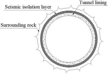
Recent earthquake events show that mountainous tunnels are vulnerable to unrecoverable damage in strong seismic areas, the anti-seismic issue of tunnels arouses much attention from earthquake engineers around the world [1]. Usually, the portal section of a mountainous tunnel is shallowly buried and the surrounding rock strength is low, which makes it especially vulnerable to earthquake damages. As shown in Fig. 1, the basic principle of the seismic isolation design is to form a soft seismic isolation layer around the outer periphery of a tunnel to insulate the tunnel from the deformation of the surrounding rock. Foamed concrete contains a large number of tiny closed pores; its porosity makes it have a low density, low elastic modulus, low shear strength, low water absorption, and good ductility.
Fig. 1Concept of seismic isolation layer for a mountainous tunnel
Therefore, foamed concrete is an ideal seismic isolation material [2]. The effectiveness of the seismic isolation layer has been verified by a series of numerical simulations and experiments [3], but the material of the isolation layer is a silicone-based material, which is an elastic material. A few studies have been conducted on foamed concrete, which is used as a seismic isolation material for mountainous tunnels [4], but research on the seismic isolation characteristics of foamed concrete mainly focuses on the cross-section of the mountainous tunnel. As a linear underground structure, the research on the seismic isolation characteristics of foamed concrete along the longitudinal direction of mountainous tunnels is very important, and is seldom carried out. In this paper, the seismic isolation mechanism and effect of the foamed concrete layer along the longitudinal direction of a mountainous tunnel were studied.
2. Calculation model
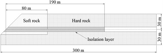
As shown in Fig. 2, longitudinal tension and compression deformations of the tunnel are caused by longitudinal non-uniform displacement of the surrounding rock under seismic waves. In this paper, the research object is the portal section of the mountainous tunnel buried in surrounding rock that is irregularly bound. A mountainous tunnel with an outer diameter of 9.3 m, made of reinforced concrete with a thickness of 45 cm, was constructed in the area where the ground conditions change sharply. As shown in Fig. 3, a seismic isolation layer is set up at the portal section of the mountainous tunnel. The length of the isolation layer is 190 m, and the thickness of the isolation layer is 20 cm.
Fig. 2The tunnel subjected to alternating tension and compression during an earthquake
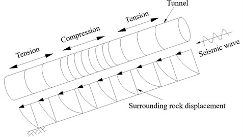
Fig. 3Schematic illustration for a tunnel with a seismic isolation layer
In this paper, the response acceleration method was used for seismic response analysis. It is well known that the pseudo-dynamic approach provides slightly higher evaluations than the dynamic analysis approach; that is, the pseudo-dynamic analysis presents more reliable and safe evaluation results [5]. First, a seismic response analysis of the surrounding rock without underground structures was carried out by an equivalent linear analysis method, based on multiple reflection theory, and the convergent mechanical parameters of surrounding rock are calculated, in addition to the surrounding rock acceleration, as the acceleration at a time when shear strain energy in the surrounding rock reached its maximum; then, the acceleration was transformed into the node force in the form of the body force, and applied to the corresponding nodes in the finite element model along the longitudinal direction of the tunnel.
Fig. 4 shows the input earthquake motion that was chosen for seismic response analysis, which was obtained by performing an amplitude component of the NS component of EI-Centro waves. The finite element analysis software ABAQUS is used in the numerical calculation [6]. The discretization of the finite element mesh and the boundary conditions of the model are shown in Fig. 5.
Fig. 4Time-acceleration curve
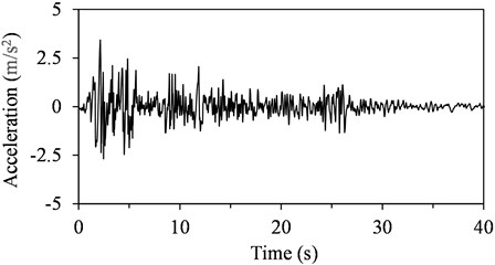
Fig. 5Discretization of the finite element mesh and the boundary conditions
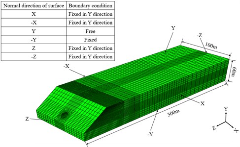
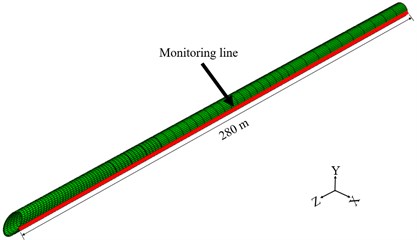
For the boundary conditions of the 3D model, the two surfaces (, ) perpendicular to the -axis are fixed in the direction, the surface normal to the positive -axis () is free, the surface normal to the negative of the -axis () is fixed, and the two surfaces (, ) perpendicular to the -axis are fixed in the direction. The convergent mechanical parameters of the surrounding rock calculated by the equivalent linear method are given in Table 1; thus, the elastic constitutive model is adopted in the three-dimensional finite element. As for the tunnel lining, the elastic constitutive model is adopted, and the mechanical parameters are shown in Table 2. In view of the volumetric hardening and rate dependence performance, the crushable foam plasticity constitutive model with volumetric hardening was chosen for the foamed concrete [4], and the mechanical parameters are shown in Table 3. The location of the monitoring line of the tunnel lining is shown in Fig. 6.
Table 1Convergent mechanical parameters of the surrounding rock
Material | Density (kg/m3) | Shear modulus (GPa) | Poisson’s ratio |
Soft rock | 1800 | 1 | 0.40 |
Hard rock | 2500 | 18 | 0.26 |
Table 2Mechanical parameters of the tunnel lining
Material | Density (kg/m3) | Shear modulus (GPa) | Poisson’s ratio |
Tunnel lining | 2500 | 33 | 0.167 |
Table 3Mechanical parameters of the foamed concrete
Elastic modulus (GPa) | Poisson’s ratio | Density (kg/m3) | Strength (MPa) | |
Uniaxial compression | Hydrostatic compression | |||
0.76 | 0.22 | 730 | 2.91 | 6.20 |
Fig. 6Monitoring line of the tunnel lining
3. Calculation results
Figs. 7 and 8 are the comparison of the analysis results of the tunnel lining axial stress and strain. As shown in the figure, there are stress and strain concentrations at the tunnel entrance and at the boundary between soft and hard rock. The axial stress and strain of the tunnel lining at the boundary between the soft and hard surrounding rock were significantly reduced after the isolation layer was set up.
Fig. 7Comparison of the analysis results of the tunnel lining axial stress
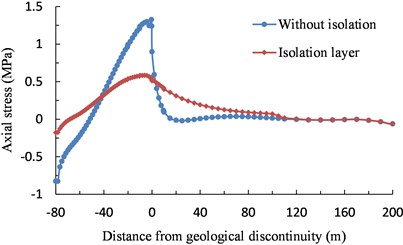
Fig. 8Comparison of the analysis results of the tunnel lining axial strain
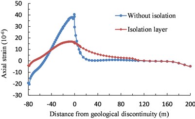
As shown in Fig. 7, after the isolation layer was set up, the peak axial stress of the tunnel lining at entrance decreased to 21.4 %, and that at the boundary between the soft and hard surround rock decreased to 43.9 %. As shown in Fig. 8, after the isolation layer was set up, the peak axial strain of tunnel lining at entrance decreased to 19.8 %, and that at the boundary between the soft and hard surround rock decreased to 41.5 %. The foamed concrete isolation layer around the outer periphery of the tunnel absorbs the shear strain transmitted from surrounding rock through its own shear deformation, reducing the influence of the surrounding rock deformation on the tunnel lining. Therefore, the foamed concrete isolation layer had a good seismic isolation effect along the longitudinal direction of the tunnel.
4. Conclusions
1) After the isolation layer was set up, the peak axial stress and strain of the tunnel lining at entrance decreased to 21.4 % and 19.8 %, respectively; and that at the boundary between the soft and hard surround rock decreased to 43.9 % and 41.5 %, respectively. The stress and strain curves along the longitudinal direction of the tunnel become smoother after the foamed concrete layer is applied.
2) The foamed concrete isolation layer absorbs the shear strain transmitted from the surrounding rock through its own shear deformation along the longitudinal direction of the tunnel and reduces the influence of the surrounding rock deformation on the tunnel lining. Therefore, the foamed concrete isolation layer has a good seismic isolation effect along the longitudinal direction of the tunnel.
References
-
Wang W. L., Wang T. T., Su J. J., Lin C. H., Seng, C. R., Huang T. H. Assessment of damage in mountain tunnels due to the Taiwan Chi-Chi earthquake. Tunnelling Underground Space Technology, Vol. 16, 2001, p. 133-150.
-
Amran Y. M. H., Farzadnia N., Ali A. A. A. Properties and applications of foamed concrete; a review. Construction and Building Materials, Vol. 101, 2015, p. 990-1005.
-
Suzuki T. Earthquake Resistance Evaluation of Shield Tunnel and Research on Seismic Isolation Method. Ph.D. Thesis, Tokyo University, Tokyo, 1990.
-
Zhao W. S., Chen W. Z., Tan X. J., Huang S. Study on foamed concrete used as seismic isolation material for tunnels in rock. Materials Research Innovation, Vol. 17, Issue 7, 2013, p. 465-472.
-
Tateishi A. A study on seismic analysis methods in the cross section of underground structures using static finite element. Structural Engineering/Earthquake Engineering, Vol. 22, Issue 1, 2005, p. 41-53.
-
Hibbit D., Karlsson B., Sorenson P. ABAQUS Analysis User’s Manual, Version 6.5. Pawtucket, RI, Hibbit, Karlsson and Sorenson Inc., USA, 2004.
Cited by
About this article

This research was supported by the National Program on Key Basic Research Project of China (973 Program) (Grant No. 2015CB057906).
