Abstract
The choice of the design operational points of the main engine to achieve the design speed of the ship determines the efficiency of the propulsion plant. At the same time, the limits recommended by the engine manufacturer for selecting the design operational points do not fully take into account current trends and can be changed. The problem of the rational use of the nominal power and specified maximum continuous rating power of the main engine operating on a fixed pitch propeller is relevant.
1. Introduction
As the main engine on transport ships, effective low speed engines operating on fixed pitch propeller (FPP) at variable speed are the most common. The power of the main engine at its operation on the propeller load curves depends on the external operating conditions and the mode of operation of the propeller. Fixed pitch propellers are characterized by high hydrodynamic performance in the design mode. When the operating conditions change, their efficiency significantly decreases, which affects the power consumption of the main engine [1].
In order to prevent overloading of the main engine operating on the FPP when assigning the design operational points, a sea (power) margin is formed. Modern studies in the field of ensuring the reliability and economy of operation of the ship show the importance of a rational choice of the “sea margin” of power [2].
The recommended power margin varies for different types and marks of main engines, different types of propellers, and the purpose of the ship.
Primary provision of power margin is determined at the stage of design coordination of the main engine and propeller. Power margin is designated in accordance with the recommendations of the engine manufacturer and operating conditions.
With technical progress, during the life cycle of a ship, changes in operating conditions are possible, allowing changes in the value of the “sea margin”. In modern studies [3, 4], there are negative consequences of a decrease in the power margin for highly loaded operational points of the main engine. There is an increase in equipment failures, a decrease in the reliability and safety of operation of low speed engines. On the other hand, a significant increase in the power margin of the main engine leads to a decrease in efficiency in favorable operating conditions, an increase in underutilized power, and an increase in the length and area of the ship’s engine room taken in designing.
At the planning stage of the voyage, there is no reliable information about changes in external factors of operation. The complexity of assessing the possible meteorological conditions, the quality of the ship hull coating against fouling, leads to an overestimation of the power margin when designating the design operational points. In the scientific literature, insufficient attention in paid to the possibility of changing the “sea margin” of the main engine power depending on the operating conditions. Little attention is paid to the issue of reducing power margin due to the mismatch of the engine and the propeller modes of operation. There is no analysis of recommendations for the value of the “sea margin” of power of various firms manufacturing low speed engines for modern transport ships.
The possibility of overloading the main engine in varying operating conditions with a reduced “sea margin” of power, a decrease in the efficiency of the main propulsion plant with an increased margin determine the relevance of the task of rational selection of the design operational points of the main engine and the corresponding “sea margin”.
Objective: to formulate recommendations for changing the “sea margin” of power by jetting additional water onto the propeller blades in order to make rational selection of the design operational points of the main engine and of the specified maximum continuous power of the main engine.
Additional supply of water to the suction surface of the propeller blade in the area of the inlet edge [5] is an analogue of the method used in aviation for increasing lift capacity – jet mechanization. The use of jet impact of water additionally supplied to the blades of the ship’s propeller allows purposefully acting on the fluid flowing around the marine screw. At the same time, the losses associated with the features of the interaction of the blade and the inflow are reduced.
The decrease in the ratio of the induced axial velocity to the velocity of the inflow occurs due to the creation of an additional lift force (thrust) on the profile, caused by a change in the “circulation” of the flow velocity. The reduction of losses for the creation of induced tip velocities is achieved by reducing the inhomogeneity of the velocity field when the direction of the velocity vector of the inflow changes. The reduction of profile losses depending on the roughness of the profile surface is achieved by the boundary layer blowing. The reduction of inductive (tip) losses occurs due to the decrease in the flow of fluid through the tip parts of the blade [6].
The supply of additional water through a slotted nozzle of the propeller allows for a controlled change in power consumption of the main engine, proportional to the increase in the parameters of the supplied water [7].
2. Methods and materials
For the analysis of the recommended values of the sea margin, the following have been used: design documentation of companies producing low speed engines, foreign and Russian publications [1-4, 8-10].
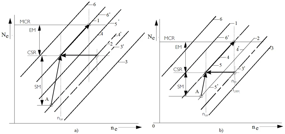
The relative position of the propeller load curves shown in Fig. 1 is formed depending on the design features and the technical condition of the propeller and the hull, the mode of operation of the ship, the conditions of navigation (change in draft, keel depth, weather conditions).
With an increase in the power required to maintain a given rotational speed, the propeller load curve becomes “heavier” (shown in Fig. 1, line 1 with respect to line 2), with a decrease - the propeller load curve becomes “lighter”. The design propeller load curve is the line passing through the point corresponding to the nominal power and nominal rotation speed.
The designates nominal maximum continuous rating (nominal MCR), at 100 % engine power and 100 % engine speed. The specified maximum continuous rated (SMCR) power of the engine installed on the ship is determined according to the hull characteristics and the manufacturer's recommendations [3], which take into account the statistical results of the operation of ships of this type and the characteristics of the propeller. In Fig. 1, the dependence of the power of the main engine operating on FPP on the rotational speed of the crankshaft is shown in logarithmic coordinates.
The parameters shown in Fig. 1 form the indicators of power margin used in determining the SMCR power of the main engine.
The set (design) speed of the ship is guaranteed to be achieved with the optimized for fuel consumption power of the main engine operating at the heavy running propeller curve and with the corresponding rotational speed (according to Fig. 1). The operating power of the main engine, at any time, should not exceed the SMCR power set by the manufacturer at the corresponding rotational speed . When the main engine operates according to the light running propeller curve (shown in Fig. 1, line 2), the rotation speed of the main engine is additionally normalized, which should not exceed to prevent overloading by the crankshaft rotation speed.
Indicators of power margin of the main engine shown in Fig. 1 can be expressed by dependencies:
• Compensation of adverse meteorological factors (SM):
• Compensation for the increase in engine power required to achieve the required ship speed with increasing towing resistance due to increased ship speed or hull fouling (EM):
Fig. 1The dependence of the power of the main engine working on the propeller load curve on the crankshaft rotation speed in logarithmic coordinates: 1 – design condition, 2 – light condition
3. Results
For the analysis of recommendations on the formation of the design power margin of the main engine, data from scientific publications were used, as well as recommendations of the MAN Burmeister & Wain and Wärtsilä firms. Summarizing the recommendations [1-4, 8-10] the main design indicators of power margin are formed and presented in Table 1.
Table 1 shows the characteristic design indicators of power margin (sea or engine margin), designed to prevent overloading of the main engine under the influence of external operating factors.
The analysis of the data in the table shows that the low speed engine installed on the ship is characterized by the presence of a significant power margin. The SMCR power of the main engine exceeds the design point by 23-46 %. The overestimation of the value of the “sea margin”, aimed at preventing engine overload, leads to the irrational use of the SMCR power of the main engine and a decrease in the operating efficiency of the ship. Based on the analysis of the data given in the table, the need was formulated and the possibility of varying the power margin depending on the operating conditions was considered.
Table 1Recommended design indicators of power margin for modern low-speed engines
Operational factor | Foreign publications | Russian publications | Low speed engine manufacturer | |
MAN B&W | Wärtsilä | |||
Meteorological factors (adverse weather conditions) | 15 %-25 % “sea margin” | 15 %-20 % “heaving” propeller load curve | 10 %-15 % “sea margin” for small ships, 20 %-30 % for large ships | 15 % “sea margin” |
Towing resistance increase | 10 %-15 % “engine margin” | 15 % | 10 % “engine margin” | 10 % “engine margin” |
Free surface correction | 5 % “сalm water powering margin” | 3 % free surface correction | 3 %-6 % | – |
Total power margin | 30 %-45 % | 33 %-38 % | 23-46 % | 25 % |
4. Discussion
Let us analyze the change in the relative position of the propeller load curves relative to the design operational points at the recommended 15 % and reduced to 5 % sea margin under the influence of an additional jet effect of water on the propeller blades.
In Fig. 2, in logarithmic coordinates, the relative position of the propeller load curves is shown for the optimal operating modes of the main engine, with the recommended (a) and reduced (b) value of the “sea margin” of power and additional water supply to the FFP blades.
Let us analyze the propeller load curves for characteristic operational modes of the main engine in changing navigation conditions. Operation of the vessel “in ballast”, under favorable weather conditions - line 3. When navigating “in load” and favorable weather conditions – line 2, with deterioration of hydrometeorological factors - line 4. During operation of the vessel and the growth of towing resistance (caused by fouling of the hull), the mode of operation of the vessel “in ballast”, when the vessel is transferred to the port of loading, under favorable weather conditions – line 5.
When the vessel is “loaded” and in favorable weather conditions – line 1 (corresponds to design propeller load curve), if hydrometeorological factors deteriorate – line 6.
When the slotted nozzles are installed on the propeller blades for supplying additional water, the design operational points of the main propulsion plant are maintained. As a result, when the water supply to the slotted nozzles is turned off, the propeller load curve of the main engine corresponds to the design one – line 1.
Due to the jet supply of additional water through the slotted nozzles of the blades, the mode of operation of the propeller and the power consumption are changed. In accordance with the recommendations of [6], a 10 % reduction in power consumption can be provided for the implementation of the variable part of the margin indicator. By purposeful changes in power consumption, additional modes of operation of the main engine were obtained.
Mathematical models and structures can be calculated by computer programs [11, 12].
The sign of change in propeller load curves (“heavy running”, “light running”) for additional modes (marked with a dash) is given relative to the corresponding mode, with a design indicator of sea margin. Fig. 2(b) shows propeller load curves of additional modes of operation: 3’- heavy running propeller curve under favorable weather conditions “in ballast”; 4’ – light running propeller curve “in load” under adverse operating conditions; 5’ – light running propeller curve “in ballast” with significant fouling of the hull and favorable weather conditions; 6’ – light running propeller curve “in load” with significant fouling of the hull and adverse weather conditions. The analysis of propeller load curves shown in Fig. 2 allows us to make recommendations on the choice of operating modes of the main engine, which has a reduced indicator of sea margin. Jet supply of water to the propeller blades allows one to purposefully change the power margin of the main engine within its variable part. The lightening of the propeller load curve, proportional to the parameters of the supplied water, compensates for the increase in power consumption and ensures the rational use of the SMCR power in most operating modes.
The analysis of Fig. 2(b) allows us to state that the supply of additional water to the propeller blades makes it possible to compensate for the insufficient “sea margin” of power and to maintain the optimum mode of engine operation in most operating modes. In general, the information presented in Fig. 2 testifies that the additional jet water supply to the propeller blades ensures non-overloading of the main engine with compensation for reduced “sea margin” of power, regardless of the presence of off-design conditions, the influence of operating conditions, and the human factor. Based on the recommendations of engine manufacturers for selecting the design operational points, indicators have been formed that characterize the “sea margin” of the main engine power. Statistical analysis of the recommended indicators taken into account when determining the “sea margin” revealed their significant variability. Based on the obtained data, a range of permissible variation of the power margin of ten percent was formed. The change in the relative position of the propeller load curve of the engine relative to the design operational point is analyzed taking into account the obtained range. The operating modes of the main propulsion plant, which allow varying the power margin, have been determined. Purposeful change in power consumption and its margin at a constant speed of rotation prevents possible overloading of the main engine in case of deterioration of operating conditions. For purposeful changes in power consumption, the jet impact of additional water supplied to the propeller is used. The results indicate that it is possible to quickly vary the “sea margin” and make rational use of the rated power and specified maximum continuous rating power of the main engine. The assessment of the thermal and mechanical tensions of the main engine operating in varying operating conditions, taking into account the variation of the “sea margin”, is of further interest.
Fig. 2Propeller load curves and indicators of the operating power margin of the main engine operating on a propeller equipped with a slotted nozzle for additional jet effect of water on the blades: a) sufficient sea margin, b) reduced sea margin; A – design operational point
a)
b)
5. Conclusions
As a result of the analysis of the recommendations of the firms manufacturing low speed engines for modern transport ships, in terms of the power margin of the main engine, a significant range of possible values (23-46 % ) of the total design margin was revealed. The analysis of the minimum and maximum indicators of the design power margin showed that the striving to prevent the overloading of the main engine leads to irrational use of the SMCR power.
It is confirmed that the SMCR power of the main engine installed on a modern transport ship has an excess value relative to that required to achieve the design speed of the ship. It has been established the ability to compensate for the reduced power margin under adverse operating conditions by changing the parameters of the propeller by jetting additional water to the blades.
The use of additional jet impact will allow designing marine propulsion plant with a reduced sea margin without the danger of overloading the main engine. With a possible implementation of the supply of additional water to the propeller blades, a 10 % variation in the value of the “sea margin” of power is allowed.
When choosing the main operating mode with a reduced sea margin due to the use of a jet effect of water on the propeller blades, additional operating modes of the main engine can be obtained. By purposefully changing the parameters of the water supplied to the propeller, rational use of the rated power can be ensured by:
– Light running propeller curve “in load” under unfavorable operating conditions;
– Light running propeller curve “in ballast” with significant fouling of the hull and favorable weather conditions;
– Light running propeller curve “in load” with significant fouling of the hull and adverse weather conditions.
The results obtained in the work will be useful in the design and operation of the main propulsion plants of ships under construction and modernization for the rational use of the SMCR power of the main engine.
On the basis of the obtained results, further study of the effect of the amount of power margin on the thermal load of the main engine is of interest, as well as the possibility of a rational choice of the SMCR power of the main engine.
References
-
Сarlton J. Marine Propellers and Propulsion. Butterworth-Heinemann, 2018.
-
Eide E. Calculation of Service and Sea Margins. M.S. Thesis. NTNU, 2015.
-
Stapersma D., Woud H. Matching propulsion engine with propulsor. Journal of Marine Engineering and Technology, Vol. 4, Issue 2, 2005, p. 25-32.
-
Listewnik J. Possibilities of reliable and safe main engine load evaluation on board ship. WIT Transactions on The Built Environment, Vol. 45, 1999, p. 259-269.
-
Osowski D., Sharatov A. UA46740U, IPC B63H 1/00. Design of Powered Screw Propeller. Ukraine, Assignee, 2010.
-
Sharatov A. Jet influence on dynamics rowing screw. Vestnik dvigatelestroeniya, Vol. 2, Issue 23, 2010, p. 82-85.
-
Sharatov A. Reducing the influence of operating conditions on thermomechanical loading of the engine by the jet of water on the screw. Vestnik Gosudarstvennogo Universiteta Morskogo I Rechnogo Flota Imeni Admiral S. O. Makarova, Vol. 5, Issue 51, 10, p. 1063-1074.
-
S70MC Project Guide, https://marine.man-es.com/applications/projectguides/2stroke/content/epub/.
-
Basic Principles of Ship Propulsion, https://marine.man-es.com/propeller-aft-ship/.
-
Test Result of Shop Trial, Mitsui-M.A.N. B&W 7s70MC Mitsui Engineering and Shipbuilding Co Ltd, 1995.
-
Sokolov S., Zhilenkov A., Chernyi, Nyrkov A., Mamunts D. Dynamics models of synchronized piecewise linear discrete chaotic systems of high order. Symmetry, Vol. 11, Issue 2, 2019, p. 236.
-
Zhilenkov A., Chernyi S. Models and algorithms of the positioning and trajectory stabilisation system with elements of structural analysis for robotic applications. International Journal of Embedded Systems, 2019, https://doi.org/10.1504/ijes.2019.10019645.
About this article

