Abstract
The paper presents the results of dynamic calculations of a road viaduct subjected to loads resulting from mining shocks. The response spectrum method and the spatial MES model were used for the calculations. The calculations were carried out for predicted accelerations of ground vibrations. The results of calculations may in future be used in the assessment of dynamic resistance of similar structures.
1. Introduction
The impact of mining shocks on surface structures in Poland is very current [1]. This is related to the extraction of such raw materials as hard coal, lignite and copper ores. Additional seismic forces generated during the mining shock can significantly affect surface structures at various stages of construction life. If the object is erected within the reach of a nearby mine, the impact of mining shocks should be taken into account at the design stage. There is often a situation in which construction works are subjected to additional seismic forces during operation (e.g. as a result of enlarging the area of a raw materials extraction [2]). In such cases it is necessary to determine the dynamic resistance of buildings and to verify the impact of mining shocks on these objects. The resistance assessment can be made, among others, with one of the following methods: response spectrum, load history, pushover. In the case of road overpasses, this is particularly important as these are buildings important from the point of view of the functioning of urbanized areas. Road viaducts and footbridges in the aspect of dynamic interactions were the subject of scientific papers [3-6].
2. FEA model
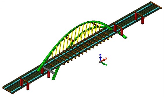
The viaduct has a beam-like bearing structure with a fixed construction height. The middle, longest span is arched. The arc has variable both height and thickness. To the arch, with a hangers spaced every 4.00 m, there is a suspended platform. The abutments are thin-walled. The outrigger wings are parallel to the axis of the viaduct. Intermediate supports were designed as double-sided with a square cross-section of 1.40×1.40 m. The bearing structure of the viaduct was designed as a five-span beam with spans 18.50 + 23.00 + 80.00 + 23.00 + 18.50 m. In the longest span, the platform is suspended to two reinforced concrete arches by means of steel hangers spaced every 4.00 m. The arcs have variable geometry and are inclined in the direction of the object axis at an angle of 81.5 and connected to each other by four horizontal concentrations. The cross-section of the platform is double-bar, designed from prestressed concrete class C40 / 50. In the access bays, the width of the girders is from 0.80 to 1.00 m (under the bridge plate), height – 1.24 m. In the arch span the beams are narrower (0.60-0.80 m). The spatial MES model was adopted for analysis. Figs. 2 and 3 present the MES model of the analyzed viaduct.
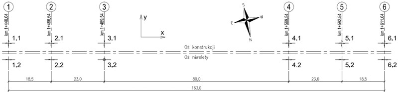
The basis for the construction of the FEM model was the executive design. On its basis, geometric dimensions as well as cross-sections of structural elements were adopted. Material parameters were also selected based on the implementation documentation. The calculations included additional masses resulting from the arrangement of finishing layers and non-structural elements on the deck slab, determined on the basis of project documentation. The boundary conditions in the model result from the bridge bearing scheme. In Fig. 4, the bearing design is shown after the project documentation, while the releases at individual degrees of freedom in the nodes are described below.
Fig. 1A view of the viaduct

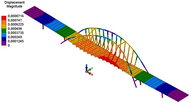
Fig. 2FEA model of the viaduct – view from the top
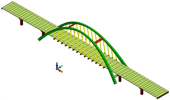
Fig. 3FEA model of the viaduct – view from the bottom
Supports 1.2, 2.2, 4.2, 5.2 and 6.2 have received the degrees of freedom associated with translation in the direction of the vertical axis and the horizontal . Supports 1.1, 2.1, 4.1, 5.1 and 6.1 have received the degrees of freedom associated with translation in the direction of the vertical axis . In support 3.2, the degrees of freedom associated with the translation in the direction of the , and axes have been received, and in the support 3.1 with the translation in the direction of the axes , . The columns in axes 2-5, on which bearings 2.1, 2.2, 3.1, 3.2, 4.1, 4.2, 5.1 and 5.2 are resting, have been fixed in the foundation.
It should be noted that in the longitudinal direction to the road axis ( axis) horizontal inertia forces will take bearings in the 3 axis, transferring them to support pillars as well as the construction of arches. In the transverse direction to the roadway axis, the horizontal inertia forces ( axis) will take bearings 1.2 to 6.2, as well as the construction of arches and arch support.
Fig. 4Diagram of the viaduct bearing
3. Dynamic analysis
The response spectrum method was used to calculate the dynamic response of the model to the kinematic necessity caused by ground vibrations from the mining shock. This method is recommended, among others by the guidelines [7], the Polish standard [8] and the European standard [9] regarding the design of facilities in the areas of natural earthquakes.
The application of a standardized standard response spectrum describing the possible ground vibrations caused by mining shocks is essential in the adopted method. Such model response spectra are created on the basis of registered ground vibrations in the analyzed area. The object is located in the Upper Silesian Coal Basin (USCB). It is therefore possible to use in the calculation the model acceleration spectrum of responses for this area (compare Fig. 5).
Due to the calculation method chosen, the analysis was divided into two stages:
– in the first stage, the values of natural frequencies and the corresponding vibration modes were determined,
– in the second stage, cross-sectional forces, displacements and stresses from predicted accelerations of ground vibrations were determined (by the response spectrum method).
Figs. 6-8 present selected characteristic forms of own vibration of the analysed model.
Fig. 5Standard acceleration response spectrum

Cross-sectional forces, displacements and stresses were determined using the spectral response method and the model acceleration response spectrum from the figure 5 for the predicted value of vibration accelerations PGAH10 = 30 mm/s2. The first 50 forms of vibrations of the analysed model were adopted for the calculations. The calculated values of cross-section forces are dynamic values without the participation of other loads. Values of obtained cross-sectional forces, displacements and stresses were compared with dimensioning values for significant load cases in static analysis from project documentation. This approach allows to estimate the level of effort of the structure in relation to the values determining the reinforcement elements adopted for implementation and the reinforcement degree of reinforced concrete elements.
Fig. 6FEA model of the viaduct – view from the bottom
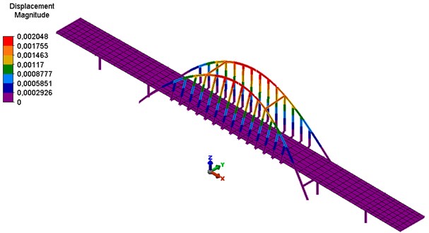
Fig. 7The second form of natural vibrations – longitudinal vibration of the bridge structure
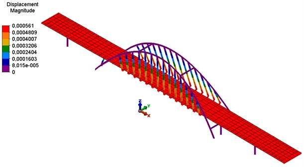
Fig. 8Sixth form of natural vibrations – transverse vibrations of the bridge structure
The analysis of the impact of vibrations on the object covered the verification of the following safety conditions:
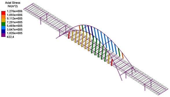
– checking the stresses in the elements of hangers,
– checking the horizontal forces affecting the bearing supports,
– checking the vertical forces acting on bearing supports,
– checking the stresses in structural elements of load-bearing arches,
– checking the cross-section forces in support pillars in axes 3 and 4,
– checking the condition of destruction of the dilatation of the object.
The above conditions in similar objects determine their dynamic resilience [4-6, 10]. Detailed results of dynamic analyses are presented, among others at work [11]. The cross-sectional forces in the viaduct hangers are shown below in Fig. 9. The values of seismic forces do not exceed 1 % of the permissible forces in hangers. It should therefore be stated that the condition of the load capacity of hangers remains fulfilled.
Fig. 9Sixth form of natural vibrations – transverse vibrations of the bridge structure
4. Conclusions
For all the dynamic resistance criteria formulated in the work, the conditions are met. With the predicted values of accelerations of ground vibrations PGAH10, the values of additional inertia forces are much lower than the values used in the design of the viaduct. The viaduct can be safely used.
The formulated criteria allow to determine the dynamic resistance or appropriate design of reinforcements depending on the diagnostic and design situation. Such formulated requirements also allow to determine the cause and effect relationship in the situation when the object is damaged as a result of the mining shock.
References
-
Tatara T. Dynamic Resistance of Building Structures under Mining Shock Conditions. CUT, Cracow, 2012.
-
Tatara T., Pachla F. Analysis of the dynamic response of masonry buildings with irregularities of localization of bearing elements due to mining shocks. Seismic Behaviour and Design of Irregular and Complex Civil Structures II. Geotechnical, Geological and Earthquake Engineering, Springer, Cham, Vol. 40, 2016.
-
Drygala I., Polak M., Dulinska J. Vibration serviceability assessment of GFRP pedestrian bridges. Engineering Structures, Vol. 184, 2019, p. 176-185.
-
Rusek J. Influence of the seismic intensity of the area on the assessment of dynamic resistance of bridge structures. IOP Conference Series: Materials Science and Engineering, Vol. 245, Issue 3, 2017, p. 032019.
-
Rusek J. Procedure of building and analysis of the information database of the resistance of existing bridge structures to mining tremors. Geomatics and Environmental Engineering, Vol. 11, Issue 4, 2017, p. 111-123.
-
Rusek J. A proposal for an assessment method of the dynamic resistance of concrete slab viaducts subjected to impact loads caused by mining tremors. Journal of Civil Engineering, environment and Architecture, Vol. 64, Issue 1, 2017, p. 469-486.
-
Cholewicki A., Chyży T., Szulc J. Designing Buildings Subject to Impacts of Mining Shocks – Instruction ITB 391/2003. Publishing house ITB, Warsaw 2003.
-
PN-B-02170:2016-12 Evaluation of Harmfulness of Vibrations Transmitted by the Ground to Buildings, 2016.
-
Eurocode 8: Design Provisions for Earthquake Resistance of Structures, 2005.
-
Ciurej H., Rusek J. Methodology of dynamic resilience assessment selected bridge structures in the LGOM area. Technical Transactions, Vol. 13, 2006, p. 31-57.
-
Pachla F. Influence of Mining Shocks on Surface Structures. ISBN 978-83-65991-65-2, CUT, Cracow 2019, (in Polish).
About this article

