Abstract
Fluid, non-stationary rigid body interaction is a commonly occurring phenomenon seen in many engineering practices. The article offers a new method using laws of classical mechanics for obtaining simplified analytical relations in analysis and optimisation tasks without using space time programming methods. In the proposed method the fluid space around the rigid body prisms is divided into two zones, pressure and suction (vacuum). The method is extensively discussed which is further extended for calculation of interaction forces and coefficients for non-stationary perforated plate with total area of perforations maintained at half the area of the complete flat plate. Experiments were performed for perforated plate in an Arm-field wind tunnel at constant speed of 10 m/s. The present work offers analysis and synthesis of specific engineering task of energy extraction from fluid in a unique way by making use of external fluid flow over a perforated plate. The fluid is assumed continuous and incompressible.
Highlights
- The proposed model is purely mathematical that allows performing tasks of analysis, optimization and synthesis for the fluid-rigid body interaction in a simplified way for engineering applications.
- High intensive time-space program computing tasks can be averted by making use of the proposed mathematical model presented in this article.
- Important to note that the proposed method is intended for analysis of non-stationary rigid body-fluid interaction and motion synthesis for a specific task of extracting energy from the fluid flow.
- The developed analytical model can be further extended in performing calculations for flying and diving robot systems in addition to specific tasks of energy extraction from fluid flow.
1. Introduction
Non-stationary rigid body motion in a fluid flow is a frequently occurring phenomenon in daily life that motivated many to perform extensive investigation to widen the scope. Available computational fluid dynamic methods based on deforming and moving mesh techniques require frequent re-meshing and constant monitoring that are time consuming and computationally very expensive [1, 2]. Thereby, the method proposed in the present article offers a simplified analytical relations for synthesis and analysis of tasks without out using space time programming methods for fluid and rigid non – stationary body interaction. Initially, the fluid space around the rigid body is divided into two zones, pressure zone and suction (vacuum) zone. The presence of vacuum zone (with a constant suction pressure) just adjacent to the body in the downstream is realized which again depended on the incoming fluid flow rate relative to the body.
In order to understand the importance of mathematical modelling technique and its wide applications for stationary and non-stationary rigid body fluid interaction, some scientific works are presented. For example, rigid body and incompressible homogenous viscous fluid interation obtained from classical Navier-Stokes equation and also rigid body motion by standard conservations laws was considered for free boundary value problem [3].
2. New mathematical model
To simplify calculations for analysis, optimization and synthesis tasks the present work offers a mathematical model without considering viscous effects of the fluid and also the fluid is spread continuous and is considered incompressible. The fluid body interaction space is divided into two – one for pressure zone and other for suction or vacuum just downstream of the body. The essence of the model is shown in Fig. 1. On the pressure sides, the theorem of change in linear momentum is applied in the differential form [4, 5], which is expressed as:
where , – mass of the fluid element, having relative velocity v against the inclined surfaces; , – the forces of elementary impulses in the direction of the normal to surfaces of the elementary area; – the angle between the flow and the surface with elementary impulse ; – elementary (small) time; , – the elementary length of the surfaces; – the width of the prism, which is constant in the case of a two dimensional task; – density.
From Eq. (1)-(4) pressure on the sides of the perforated plate can be expressed as:
Also pressure due to normal forces along the elementary area is given by:
where , – flow presure on sides with length and , Fig. 1.
Fig. 1Pressure distribution for rectangle cross section flat plate prism body element
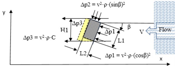
In the new mathematical model proposed in the present work, the suction or the vacuum zone realised as obtained from flow simulations and also the suction pressure just along the edge of the body in the downstream in a small border layer is taken to be constant and expressed as (see Fig. 1) [6]:
where – constant, to be found out experimentally or by computer modelling. It is realised that the value of varies from 0 < < 1 for subsonic flow.
From the new mathematical model, the interaction force , acting on the body along the -direction (along the flow) as an approximate from the law of classical mechanics for flat plate prism in 2D is expressed as Eq. (10):
where – the ratio of edges (); – section height, perpendicular to the flow Eq. (11) (Fig. 1):
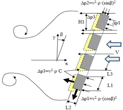
The obtained relationships Eqs. (1)-(11) allow the determination of the forces of interaction between the flow and the object for bodies of a more complex shape, such as a perforated plate prism. In this case, the interaction pattern is shown in Fig. 2.
For perforated plats with inequality Eq. (12), Fig. 2:
where – gap of rectangle perforation of prism, interaction force Eq. (10) is taken in the following form (13):
where – total number of elements between perforation on the plate, Fig. 1-3.
A case, where the inequality in Eq. (12) is not met or if perforation gap is very small, requires additional research.
Fig. 2Pressure distribution for rectangle cross section flat perforated plate prism body. L3 – gap of rectangle perforation of prism
In order to obtain the interaction force from the proposed mathematical model, computer flow simulations are performed using Ansys 19.2 and validated with experimental results as discussed in the following section.
2.1. 3D perforated plate analysis
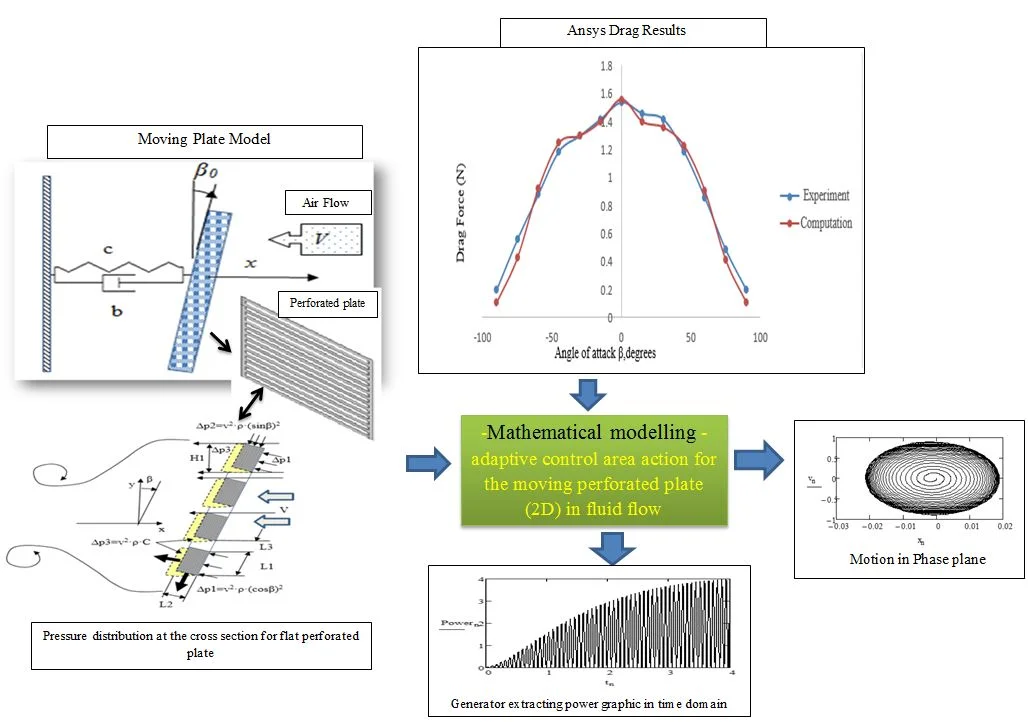
A square perforated plate Fig. 3, whose perforations aligned horizontal, is subjected to a wind flow of constant velocity 10 m/s at different angle of attack (Fig. 2). The results obtained from the flow simulations and experiments are compared and are shown in the Fig. 4. Steady state RANS equation is solved using - realizable turbulence model. Tetrahedron mesh with a total of 2,46,616 elements is used. The thickness of the plate is 6 mm, Fig. 1. Acordingly 5 mm; 6 mm; 15, shown in Fig. 3.
Fig. 3Details of square perforated plate, all dimensions in mm
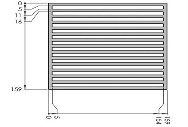
Fig. 4Comparison of results from computation and experiments in wind tunnel for perforated plate
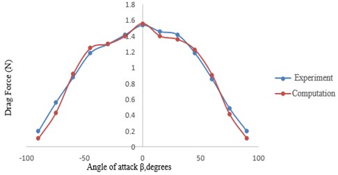
From the graph, Fig. 4. analysis, the validation of computer modeling and experimental results are satisfactory. In addition, the comparison of computational and experiment results shows that there really exists an inequality Eq. (12) in the inclination angle beta . This means that Eq. (13) can only be used within the range: . It was found that the mean value of the perforated plate investigated here within these limits Eq. (12), constant is: 0.065. Outside this range, additional research is required.
3. Results and discussion
3.1. Theory for moving perforated plate
The perforated plate in two dimensional (2D) analysis model in the translation motion is given by Eqs. (13)-(15). Model includes linear spring with stiffness and linear damper with constant . According to the approximation theory, the relative interaction velocity is expressed as:
where – fluid velocity; – plate velocity along axis.
Differential equation of plate motion along axis for the negligible thicknes of plate, when , is given by (15):
where , , , – mass, displacement, velocity and acceleration of plate respectively, – midlle value of interaction area parameter; – constant of area exchange; – air density; – vacuum constant; – plate angle; – air flow absolute velocity; – adaptive control area action.
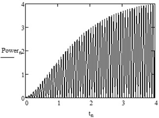
Modelling results are shown in Fig. 5-8 with parameters: 1,56 kg; 3061 kg·s-2; 5 kg·s-1; 0,04 m2; 0,5; 0,065; 10 m·s-1; 1,2047 kg·m-3; /6.
Fig. 5Moving plate model in air flow
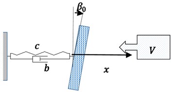
Fig. 6Plate displacement in time t
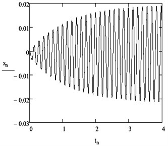
Fig. 7Motion in phase plane
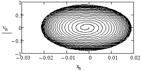
Fig. 8Generator’s extracting power (Power = bv2) graphics in time domain
4. Results and discussion
1) An approximate analytical method, not considering the viscous effect of the fluid for perforated flat plate-fluid interation formed from the law of classical mechanics, is presented in this work.
2) From the numerical simulations, it is concluded that for fluid –rigid body interaction space can be split into two - one on the pressure side and other on the suction or vacuum side just adjacent to the body in the downstream.
3) The main important point is that the proposed method is intended for analysis of non-stationary rigid body – fluid interaction and motion synthesis for a specific task of extracting energy from the fluid flow.
5. Conclusions
1) As the proposed method is purely mathematical, it allows performing tasks of analysis, optimisation and synthesis for the fluid-rigid body interaction in a simplified way for engineering applications.
2) The developed analytical model can be further extended in performing calculations for flying and diving robot systems in addition to specific tasks of energy extraction from fluid flow.
3) High intensive time-space program computing tasks can be averted by making use of the proposed mathematical model presented in this article.
References
-
Crank J. Free and Moving Boundary Problems. Oxford University Press, 1984, p. 425.
-
Finlayson B. A. Numerical Methods for Problems with Moving Fronts. Ravenna Park, Ravenna Park Publishing, 1992, p. 605.
-
Cumsille P., Takahashi T., Well possedness for the system modelling the motion of a rigid body of arbitrary form in an incompressible viscous fluid. Czechoslovak Mathematical Journal, Vol. 58, Issue 4, 2008, p. 961-992.
-
Goldstein H., Poole C., Safko J. Classical Mechanics. Third Edition, Wesley, 2015, p. 625.
-
Meriam J. L., Kraige L. G., Bolton J. N. Engineering Mechanics: Dynamics. 8th Edition, Wiley, 2015, p. 736.
-
Tipans I., Viba J., Irbe M., Vutukuru S. K. Analysis of non-stationary flow interaction with simple form objects. Agronomy Research Journal, Vol. 17, 2019, p. 1227-1234.
Cited by
About this article

