Abstract
Use dynamics theory to establish finite element model of the needle valve assembly of marine diesel engine in the LS-DYNA and transient analysis calculation by explicit solving method. Analyze the time series diagram of equivalent stress of the impact surface and classify the impact phase according to the kinetic theory. Finally, the strength check is performed in the phase where the influence of the impact is most affected by analyzing the calculated equivalent stress results.
Highlights
- Dynamic analysis of impact on needle valve assembly under ultra high pressure conditions
- Analysis sequence from contact surface to whole valve assembly
- Using finite element sampling to generate time series diagram of impact surface equivalent stress
1. Introduction
As one of the key components of the marine diesel engine injection and combustion system, the injector ejects the diesel to the cylinder in the highly atomized state by using the high-pressure oil pump to achieve good cooperation with the compressed air and the combustion chamber [1]. The core power component of the injector is the needle valve assembly which includes needle valve and needle body. In order to achieve the purpose of the fully combustion of fuel, the injection need to be highly atomized with high frequency [2]. High frequency means the injector need to change the status between close and open very fast, so the needle valve will hit the needle body quickly at high frequency. On the other hand, the needle valve assembly is a precision coupler, which is accurate with the clearance requirements, generally only 0.002 mm-0.006 mm and extremely small deformation can cause an unacceptable condition [3].
Under the dual action of high pressure and high-speed impact, it is very significant to analyze the strength of needle valve assembly to make sure the injection and combustion system of marine diesel engine work normally. A common method for analyzing is calculating the stress by the finite element analysis [4]. Differing from the static structure analysis, it is necessary to use dynamics theory to establish a finite element model to analyze the stress of the needle valve assembly during impact [5].
2. Establishment of finite element model
This calculation uses LS-DYNA module of Ansys for finite element modeling and transient analysis calculation by explicit solving method. The focus of the analysis is the stress of the needle valve assembly during the period of impact and the strength check according to the fourth strength theory, so choose part of the needle valve and the impacted part of the needle body to establish the finite element model, which is shown in Fig. 1.
2.1. Material definition
Needle valve assembly consists of needle valve and needle body. The material of these two parts is alloy with different processes and can be defined in the software with several of material properties which is shown in Table 1.
Fig. 1Part of the model for finite element model (section)

Table 1Detailed material properties of needle valve assembly
Part Name | Material name | Young’s modulus (MPa) | Poisson’s ratio | Yield strength (MPa) |
Needle valve | Chromium nickel alloy | 2.06E+05 | 0.3 | 950 |
Needle body | Chromium nickel alloy | 2.06E+05 | 0.3 | 950 |
2.2. Mesh
In order to ensure the accuracy of the calculation, the needle body and the needle valve are sliced and hexahedron mesh is generated for each part. The method of generating the grid uses the grid generation function of Ansys [6].
The size of the mesh requires stress wave theory as a reference. The velocity of the tress wave in materials is calculated by the properties of materials [7]. The equation is:
where is the velocity of the stress wave, is Young’s modulus and is the density of materials.
According to the material properties, the velocity of the stress wave in this calculate is:
The time of the impact is 0.01 ms according to the measured velocity curve, so the minimum value of the size of mesh is:
After choosing different size for each part and the generation of face mesh with refinement on contact surface, the generated mesh is shown in Fig. 2. The statistical result is that the number of nodes is 521743 and the number of elements is 578271.
2.3. Boundary conditions
For transient analysis, the boundary conditions only need to define the impact velocity of the needle valve and support of valve body. The velocity of the needle valve is 1600 mm/s whose direction is vertical down to the needle body. As for the support, chose to fix the needle body.
Fig. 2The mesh model of the impacted part of needle valve assembly


3. Results of analysis
Analyze the results in three aspects as follows:
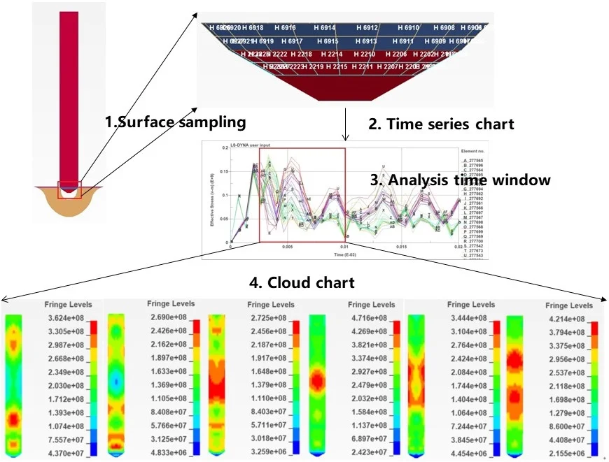
1) Analyze the stress of the impacted surface. Select sampling elements on the impact surface and observe the time series diagram of the equivalent stress for all points taken. The equivalent stress of the impact surface can be obtained, and the period of which the impact has a larger impact can be analyzed therefrom [8].
2) Analyze the equivalent stress cloud charts of the period that the influence of the impact is larger.
3) Check the strength of the impacted part of the needle valve assembly and identify the risk location according the result of the stress.
3.1. Equivalent stress (von-mises) curve of the impact surface
Select the sampling elements on the impact surface of the needle valve and the needle body respectively, which is shown in Fig. 3. After selecting the elements, export the time series diagram of corresponding equivalent stress with the post-processing software like Fig. 4 and Fig. 5. According to the measured velocity curve of needle valve, the impact will occur within 0.01 ms. So the focus of the analysis is on this period and the rest of time series diagram which is in the range of 0.01 ms to 0.02 ms is used to observe the follow-up trends and the condition of its convergence.
Fig. 3Sampling elements on the surface of impact

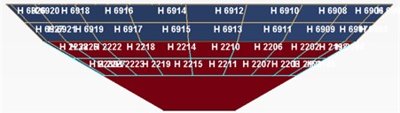
Fig. 4Needle body’s time series diagram of equivalent stress
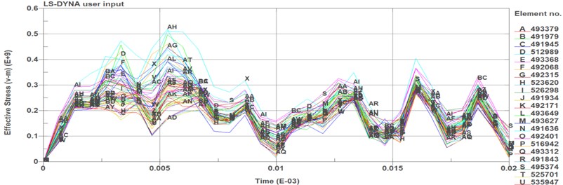
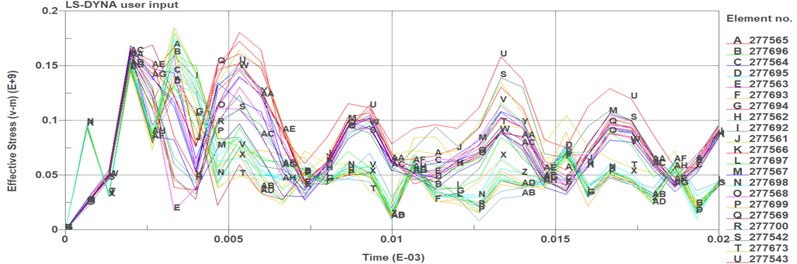
Fig. 5Needle valve’s time series diagram of equivalent stress
Observing the results from this two time series diagram of equivalent stress within 0.01 ms, there are two large stress fluctuations at 0.0025 ms and 0.008 ms on the impact surface of the needle body. The maximum equivalent stress is about 460 MPa at the time around 0.008 ms. Then the equivalent stress shows the trend of continuous oscillation within the time period after 0.01 ms and the maximum value of this period is decreasing gradually.
On the other hand, one large stress fluctuation occurs at 0.0025 ms on the impact surface of needle valve, whose maximum equivalent stress is about 180 MPa. Then the series diagram of equivalent stress is flattened after some small oscillations.
Analyzing this two time series diagrams of equivalent stress, the entire 0.02 ms time period can be divided into the following phases as is shown in Table 2. In the phase 1, equivalent stress increase gradually. A large stress fluctuation occurred around 0.0025 ms in both needle valve and needle body. It means that this moment which impact energy reaches the climax is around the 0.0025 ms during the period of impact. After this moment, the status of the impact is in phase 2, equivalent stress decrease because of the consumption of the energy, and the influence of the impact is became weaken gradually. In phase 3, the needle valve and valve body is already separated and the concussion of equivalent stress shows that the impact will spread by the form of waves from the impact surface. However, the specific situation is different in needle valve and needle body because of the different boundary conditions in the finite element model and the difference of the material physical parameters and component quality.
Table 2State phases in the 0.02ms time period
Period | Phases |
0 ms-0.005 ms | Impact starting, equivalent stress increases during this period |
0.005 ms-0.01 ms | Impact continue, equivalent stress decrease gradually |
0.01 ms-0.02 ms | Separated, equivalent stress vanish in the form of oscillation |
3.2. Cloud chart of equivalent stress (von-mises)
Because the output of results is 30 frames set by the solving parameter of finite element model, the cloud chart need to be chosen with larger equivalent stress for stress analysis and strength checking. According to the series diagram of equivalent stress on the surface of the impact, choose the cloud chart during the period from 0.0025 ms to 0.01 ms to analyze.
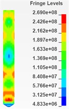
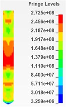
As is shown in Fig. 6 and Fig. 7, there are 6 cloud charts of valve body and 6 of the needle valve.
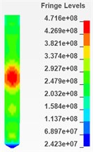
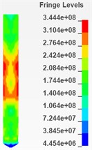
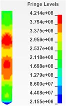
According to the respective equivalent stress cloud charts, it is found that the equivalent stress of the impacted part of the needle body is less than 573 MPa during the period from 0.0025 ms to 0.005 ms and this period is considered to be more affected by the impact. Therefore, it can be determined that during the impact process, the maximum equivalent stress of the needle body is 573 MPa. Similarly, the maximum equivalent stress of the needle valve is 471 MPa during the period from 0.0025 ms to 0.005 ms and it can also be determined that during the impact process, the maximum equivalent stress of the needle valve is 471 MPa.
Fig. 6Cloud chart of impacted part of needle body from 0.0025ms to 0.005ms (top view)
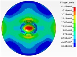
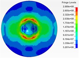
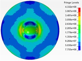
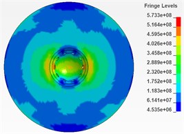
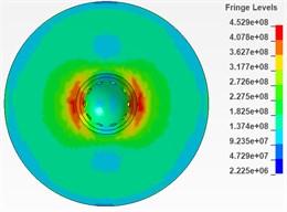
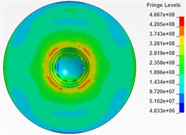
Fig. 7Cloud chart of impacted part of needle valve from 0.0025ms to 0.005ms (section)

This analysis uses the fourth strength theory for strength checking which will compare the value of equivalent stress multiplied by safety factor with the yield strength. According to the material property, the yield strength of both the needle valve and needle body material is 950 MPa. Under the premise of the value of the safe factor equals 1.5, the comparison formula is as follows. Both the needle valve and needle body are satisfied the requirement of strength:
4. Conclusion
The analysis of the stress of needle valve assembly is focus on below part of the needle valve and the impacted part of the needle body around the impacted surface. According to the result of the analysis, there are two conclusions as follows:
1) According to the time series diagram of equivalent stress and the measured velocity curve, the impact period is from 0 to 0.01 ms, and the maximum value of the equivalent stress is 480 MPa which is occurred on the impact surface of needle body.
2) According to the cloud chart and the fourth strength theory, both of the needle valve and needle body are satisfied the requirement of strength under the premise of the value of the safe factor equals 1.5.
References
-
Abo-Elfadl S., Ali A. S., Siliman M. H. Modeling and simulation of the common rail fuel injection system of the diesel engine. Computer Engineering Conference, 2018, p. 134-140.
-
Mohebbi M., Aziz A. A., Hamidi A., et al. Modeling of pressure line behavior of a common rail diesel engine due to injection and fuel variation. Journal of the Brazilian Society of Mechanical Sciences and Engineering, Vol. 25, Issue 3, 2017, p. 661-669.
-
Xiuquan Q. Analysis of common faults of marine diesel fuel injector. Equipment Management and Maintenance, Vol. 17, 2018, p. 91-92.
-
Qi B., Zhang Y., Guo D. Study on seal performance of injector nozzle in high-pressure common rail injection system. Journal of the Brazilian Society of Mechanical Sciences and Engineering, Vol. 40, 2, p. 2018-97.
-
Qian D. S., Liao R. D. Research progress on leakage of plunger pump of high pressure oil pump of diesel engine. Lubrication Engineering, Vol. 39, Issue 9, 2014, p. 108-115.
-
Bich D. H., Dung D. V., Nam V. H. Nonlinear dynamic analysis of eccentrically stiffened imperfect functionally graded doubly curved thin shallow shells. Composite Structures, Vol. 96, Issue 4, 2013, p. 384-395.
-
Shi J., Chopp D., Lua J., et al. Abaqus implementation of extended finite element method using a level set representation for three-dimensional fatigue crack growth and life predictions. Engineering Fracture Mechanics, Vol. 77, Issue 14, 2010, p. 2840-2863.
-
Qiu T., Liu T. X., Xiao Dong A.-N., et al. Research on movement characteristics of needle valve in common rail injector for diesel engine. Acta Armamentarii, Vol. 38, Issue 10, 2017, p. 2069-2074.
About this article

The authors gratefully acknowledge the support from National Natural Science Foundation of China (Grant No. 51574161).
