Abstract
The paper presents design solutions for reduction of gasdynamic noise from the passenger car exhaust system end pipe mouth. Data on overall levels and waterfalls of noise pressure obtained by experiment are provided. The best exhaust system design has been defined based on the results of the general levels analysis.
1. Introduction
When the engine is working, combustion products are formed that have a high temperature and toxicity. For their cooling and removal from the cylinders, as well as to reduce toxicity and reduce the noise created by the exhaust gases, an exhaust system is provided in the vehicle structure. The exhaust system consists of a sequential chain of elements, each of which performs a specific function.
In the external noise of an intensively accelerating passenger car, the loudest source is the noise of the engine exhaust system. The removal of gases from the engine is carried out through converters, pipelines, mufflers. Elements of the exhaust system properly selected for acoustic parameters and packaged (mufflers and resonators) can reduce the exhaust noise and significantly reduce the cost of reducing the noise of the car as a whole. Due to this, there can be no doubt about the relevance of the development of resonators’ and mufflers’ designs.
In this paper, four concept designs of mufflers and resonators were developed to reduce the noise of the exhaust system. The purpose is to select the best design among the suggested concept variants. According to the selection results, a calculation study is carried out on the transmission loss parameters with subsequent multi-criteria design optimization. According to the optimization results, a resonator and muffler design is manufactured, and the efficiency is checked in the operation modes standardized not only by UNECE Regulation No. 51 – Rev. 3, but also by the developed modes.
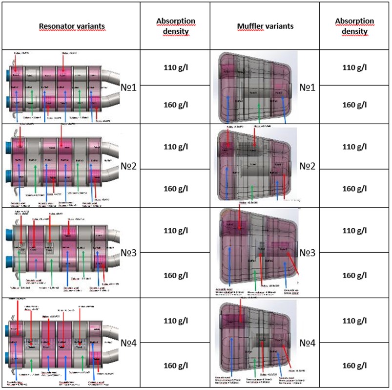
To reduce the released noise, resonators and mufflers are developed taking into account the packaging of the car (as shown in Fig. 1).
In resonator No. 1 there are two longitudinal flow tubes with perforations (shown by red arrows). The pipes pass through the entire cavity volume divided by partitions into 6 even volumes, 4 of which are filled with sound-absorbing material (shown in purple). Green arrows indicate empty volumes connected to volumes with sound-absorbing materials by perforated partitions.
Resonator No. 2 in contrast to resonator No. 1 has no flow tubes. In volumes without sound-absorbing material, pipes are absent.
Resonator No. 3 has a perforated tube in the first three volumes in the center of the resonator, the other three volumes are designed like those of resonator No. 1.
Resonator No. 4 in contrast to resonator No. 3 has an elongated perforated tube reaching up to the 5th volume.
Muffler No. 1 consists of three volumes separated by perforated partitions, two of which are filled with sound-absorbing material (shown in purple). The inlet pipe has perforations in the first chamber, and the exhaust pipe has perforations along the entire length of volume 3.
Muffler No. 2, unlike muffler No. 1, has an elongated intake pipe with perforations in the first and second chambers.
Muffler No. 3, unlike muffler No. 1, has enlarged chambers 1 and 3 with sound-absorbing materials.
Muffler No. 4, unlike muffler No. 3, has a reduced chamber 3 and perforation of the exhaust pipe in chamber 2.
Fig. 1Variants of resonators and mufflers
Measuring instruments: measuring and recording unit LMS Scadas Mobile (with 8-channel input modules SCM-V8-E in 5-slot case of recorder SCR205, ICP Microphones GRAS 1/2 type 40AE with GRAS preamps type 26CA, LMS software TEST / LAB 14A for data processing and analysis.
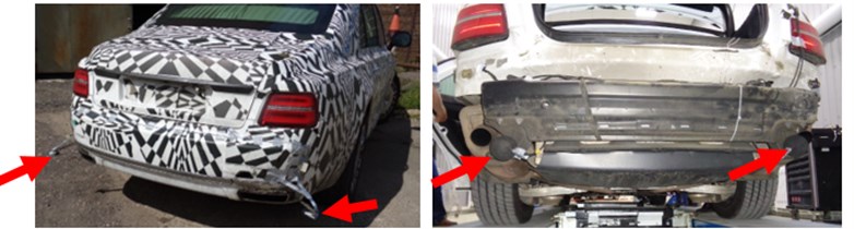
Noise measurement was carried out at the distance of 14 cm at the angle of 450 at the exhaust pipe sections (shown in Fig. 2).
Fig. 2Microphones at the left and right sections of exhaust pipes (a complete set with a rear bumper and end inserts of exhaust system)
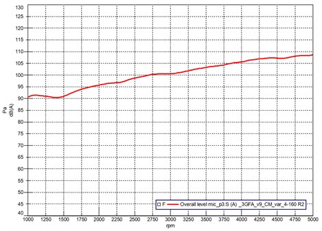
As an example, the measurement results are given: sonograms in Fig. 3 and overall noise levels in Fig. 4 in the configuration of the exhaust system of resonator No. 4 and muffler No. 1. Measurement mode is fast acceleration.
Fig. 3Sonogram of noise at the cut of the left and right exhaust pipes
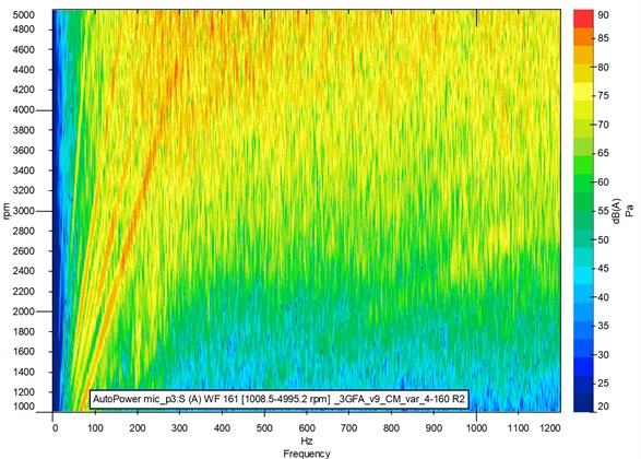
Fig. 4Overall noise levels at the cut of the left and right exhaust pipes
For this variant of the exhaust system, four rotational harmonics can be viewed in the exhaust noise in the frequency range up to 300 Hz (Fig. 3). The maximum noise level of the exhaust system is 108.4 dBA on the left and 108.7 dBA on the right.
Table 1Overall sound pressure levels
Muffler No. 0 | Resonator | Overall lever, dBA left/right | Resonator No. 0 | Muffler | Overall level, dBA left/right |
No. 1 | 113,5 / 112,6 | No. 1 | 115,6 / 113,9 | ||
No. 2 | 108,9 / 108,6 | No. 2 | 115,3 / 113,3 | ||
No. 3 | 110,1 / 108,0 | No. 3 | 112,7 / 111,9 | ||
No. 4 | 108,4 / 108,7 | No. 4 | 115,7 / 112,8 |
The results of measurements of the tested variants of exhaust systems with regular muffler No.0 and regular resonator No. 0 and developed resonators and mufflers are shown in Table No. 2. The lowest levels of overall noise are in case of installation in the exhaust system of muffler No. 3 with regular or standard resonator No. 0 and resonator No. 4 with standard muffler No. 0.
Based on the experimental study, the packaging of the exhaust system was chosen. Further optimization of the selected design by the criterion, which is the specified sound pressure spectrum at the end-pipe cut using finite element modeling (Siemens Simcenter 3D) and multi-criteria optimizer with the SHARPA optimization algorithm (Siemens HEEDs) is needed.
2. Conclusions
1. When muffler No. 3 and resonator No. 4 are installed, while accelerating the exhaust system has lower levels of overall noise.
2. Muffler No. 3 has a large volume with an absorbing material, therefore the medium and high-frequency range of sound pressure is very well extinguished in this range.
3. Resonator No. 4 with a central perforated tube also has a large amount of volume, which indicates efficient operation in the medium and high-frequency range.
4. To reduce noise at low frequencies, if this is not broadband noise, it is essential to design a Helmholtz resonator with sufficient -factor and take temperature into account, and for low-frequency broadband noise, it is necessary to design a restrictor, having pre-calculated gasdynamics to eliminate noise generation in the restrictor itself at maximum engine speed.
References
-
http://opelastraj.ru/osobennosti-konstruktsii-dvigatelej-s-turbonadduvom.html, (in Russian).
-
Galevko V. V., Rakhmatov R. I. Constructive Solutions to Reduce Sound Radiation from Surface JBSO. Moscow Automobile and Road Construction State Technical University (MADI), Vol. 3, Issue 46, 2016, p. 3-10.
-
Rakhmatov R. I., Galevko V. V., Nadareishvili G. G., Yudin S. I. Tendencies of development of exhaust systems of contemporary vehicles. Natural and Technical Sciences, Vol. 6, Issue 74, 2014, p. 92-96.
-
Rakhmatov R. I. Improvement of acoustic characteristics of motor vehicle intake system based on calculation and experimental research. Lecture Notes in Mechanical Engineering, 2019, p. 2311-2322.
-
Rakhmatov R. I. Modern vehicle exhaust system design dynamic analysis. Akustika, Vol. 32, 2019, p. 351-354.
About this article

