Abstract
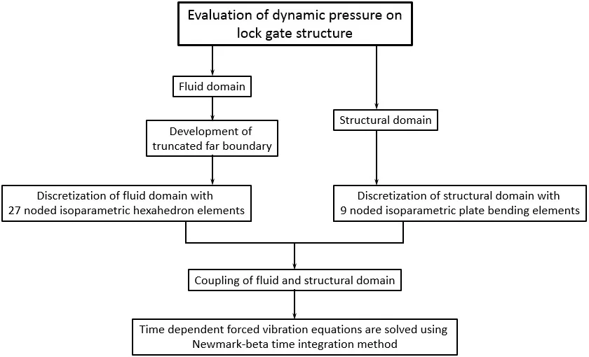
The effect of fluid on the dynamic pressure distribution of a rectangular lock gate structure subjected to external harmonic ground acceleration is studied. The fluid is assumed to be inviscid and incompressible, having an irrotational flow. Pressure for fluid domain and displacement for lock gate are considered as nodal variables in the finite element formulation. The interaction of coupled problem is maintained by transferring acceleration of the lock gate to fluid and pressure of the fluid to lock gate. Mindlin’s plate theory is used to formulate the lock gate. The Laplace equation is solved using Fourier half range cosine series expansion to truncate the far boundary nearer to the lock gate. The time dependent forced vibration equations are solved by using Newmark-beta time integration method.
Highlights
- Dynamic pressure developed on lock gate structure is carried out using a computer code written in FORTRAN, based on finite element method.
- Nine noded isoparametric plate bending elements with five degrees of freedom at each node have been used for discretization of the structural domain.
- Twenty-seven noded isoparametric hexahedron elements have been used for discretization of the fluid domain.
- The top free surface of fluid domain is assumed to be undisturbed.
- Two boundary conditions viz. clamped and simply supported on all edges, are considered.
1. Introduction
Fluid-structure interaction (FSI) phenomena occurs in numerous structures like lock gates, dams, marine offshores structure, tanks, piping systems, bridges, chimneys etc. Such structures, during their life period, come in direct contact with fluids and hence dynamic loading is induced from the fluid, thereby necessitating analysis of such interaction phenomena for safe and economical design. Interaction between lock gate and the surrounding reservoir fluid significantly affects response of the lock gate. It is therefore important to study the fluid-structure interaction effects on the vibration of a lock gate.
In general, the natural frequencies of a vibrating structure in contact with fluid are reduced as compared to that without interacting with fluid. But, the scenario becomes quite complicated when the external force or excitation comes into the picture. The external force developed may be due to sloshing at the top of fluid surface, wind loading, ground motion, etc. and it is really a typical and interesting problem to predict the response of the structure in these kind of loading conditions.
Many researchers investigated the effect of fluid on the response of the plate, either in contact with or immersed in a fluid. A technique was developed to investigate the dynamic response of the dams subjected to a harmonic horizontal ground motion [1]. A dam-reservoir system was investigated the effect of hydrodynamic pressure of the fluid on dam subjected to harmonic ground motions [2]. The vibration characteristic of circular plate resting on sloshing liquid surface using Rayleigh-Ritz method was investigated [3]. The condition for truncated far-boundary using classical wave equation assuming the water as inviscid and incompressible was developed [4]. The fluid-structure interaction effect on lock gate using finite element method with both incompressible and compressible fluid [5, 6]. A novel procedure to determine the hydrodynamic pressure on dam was developed [7].
In the present investigation, the dynamic pressure developed on the lock gate structure, simply supported on all edges, is studied. The top free surface of the fluid domain is assumed to be undisturbed. The effect of aspect ratio of lock gate on dynamic pressure is also investigated.
2. Model of investigation
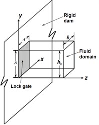
The mathematical model of the lock gate used in the present study is shown in Fig. 1.
The far boundary is truncated close to the lock gate as to minimise the computation time without influencing the results, very much. The material of the lock gate is assumed to be homogeneous, isotropic and linearly elastic. At the top surface of the fluid domain, it is assumed that there is no surface wave i.e. undisturbed free surface.
The formulation of lock gate and fluid domain are presented separately in the following section.
Fig. 1Model of lock gate structure
3. Mathematical formulation
3.1. Fluid domain
For inviscid and incompressible fluid, neglecting the static pressure, the value of dynamic pressure of fluid may be written using Laplace equation and is given by:
where, is the Laplacian operator and is the dynamic pressure at a point at any instant of time over and above the static pressure.
The pressure gradient is considered at the fluid-structure interface and the pressure is assumed to be zero at the truncated far boundary surface. Further, it is assumed that there is no pressure change across the side surfaces of the fluid domain due to small generated displacement of the lock gate as it vibrates along the rigid wall. Further, it is assumed that there is no pressure change across the bottom surface of the fluid domain. For undisturbed free surface condition, it is assumed that there is no surface wave i.e. atmospheric pressure is assumed to be constant at the top free surface.
Using the Fourier half range cosine series, the boundary condition at the far truncated boundary may be developed and represented as:
where, is fluid depth, is fluid density, is acceleration of fluid, and .
where, is the truncated length and:
where , and denote the axis along the side, depth and fluid length, respectively.
3.2. Fluid domain
The undamped forced vibration equation of the lock gate is given as:
where, [] and [] are the mass and stiffness matrices of the lock gate, respectively, and are the displacement and acceleration vector, respectively, external load vector.
4. Finite element formulation
The pressure at any point inside an element may be represented as:
where, , are the interpolation functions and nodal pressure values corresponding to node respectively and is the number of nodes in the element.
The weighted average integral of Eq. (1) using Galerkin’s weighted residual method may be written in concise form to represent the fluid domain as [8]:
where, , , refers to the total boundary surface of the fluid domain and .
The boundary term may split into several components considering the boundary conditions mentioned earlier and are available in literature [8]:
where:
Here, twenty seven noded isoparametric brick element and nine noded isoparametric plate element are used to discretise the fluid domain and lock gate, respectively.
5. Coupled interaction between fluid and lock gate
The motion of the fluid-structure interface is prescribed by the movement of the lock gate. Replacing by in Eq. (7), the resulting equation is yielded as:
When the effect of dynamic pressure is added to Eq. (4), it may be written as:
where, is formed due to the dynamic pressure of fluid at the interface.
After further simplification, the above equation may be represented as [8]:
where, .
Eq. (10) is solved using Newmark-beta iterative method with and as 0.5 and 0.25, respectively. The dynamic pressure is evaluated for a simply supported lock gate structure. The thickness of the lock gate restricted to 0.006 m as per the Indian Codal provision [9].
The material properties of the lock gate and the fluid considered are: Density () of the material of the lock gate = 7850 Kg/m3, Young’s modulus () of the lock gate is 2.0×10¹¹ N/m2, Shear modulus 0.76×10¹¹ N/m2, Poisson’s ratio 0.3, Density () of the fluid is 1000 kg/m3.
6. Results and discussion
The dynamic pressure on the lock gate is evaluated and presented in the form of coefficient of dynamic pressure, (). The lock gate is subjected to a sinusoidal external excitation of amplitude 0.5g. The top surface of the fluid gets disturbed when it is subjected to external excitation. However, for the small rise of surface waves, the top free surface may be assumed to be undisturbed or linearised. In the present study, the top free surface is considered to be undisturbed.
6.1. Convergence study
A square lock gate, simply supported on all edges of 1.0 m width (B), and 0.006 m thickness (), subjected to a sinusoidal ground acceleration with 10 rad/sec excitation frequency is considered for study. The width, depth and length (truncated length) of fluid domain are taken as 1.0 m. A convergence study is carried out by plotting dynamic pressure coefficient, at the midpoint of the lock gate against the number of elements and shown in Fig. 2.
Fig. 2Convergence study (recorded at t= 0.3 sec)
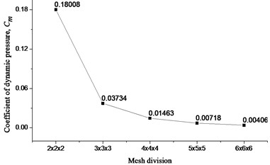
It can be clearly observed that after 4×4×4 mesh division, the value of is about to be converged.
6.2. Truncation of far boundary
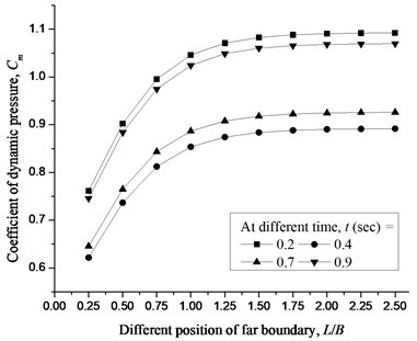
The applicability of the present formulation is demonstrated by numerically truncating the far boundary closer to the lock gate. A square lock gate simply supported on all edges of 1.0 m width, and 0.006 m thickness subjected to a sinusoidal ground acceleration with 100 rad/sec excitation frequency is considered for study. The truncated length is varied as 0.25m, 0.5 m, 0.75 m, 1.0 m, 1.25 m, 1.5 m, 1.75 m, 2.0 m, 2.25 m and 2.5 m. The at the centre of lock gate is observed and demonstrated in Fig. 3. It is found that the value of coefficient of dynamic pressure is not significant after the truncated length of 1.5 m. Hence, the parametric study is extended in the next section for a truncated length of 1.5 m.
Fig. 3Coefficient of dynamic pressure, Cm at the centre of lock gate for different position of far boundary
6.3. Validation of results
A problem of rectangular lock gate, simply supported on all edges of 1.0 m width, and 1.5 m height () subjected to a sinusoidal ground acceleration of 0.5 g amplitude, is considered for validation. The dynamic pressure developed on the lock gate with very large thickness (i.e. 10) is compared with analytical [1] and numerical [5] results. The comparison of results is found to be very close to each other and demonstrated in Fig. 4.
Fig. 4Validation of result
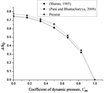
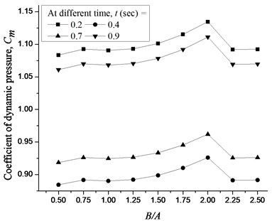
Fig. 5Coefficient of dynamic pressure, Cm at the centre of lock gate for different height of the lock gate
6.4. Different aspect ratio of lock gate
A simply supported lock gate subjected to a sinusoidal ground acceleration with 100 rad/sec excitation frequency is studied. The height (0.5 m, 0.75 m, 1.0 m, 1.25 m, 1.50 m, 1.75 m, 2.0 m, 2.25 m and 2.5 m) of the lock gate is varied keeping the width and thickness of the lock gate as 1.0 m and 0.006 m, respectively. The variation of Cm is demonstrated in Fig. 5 for different height of the lock gate.
It is observed that when the height of the lock gate is increased up to two times of width of lock gate, the effect of dynamic pressure is increased and after that the effect of dynamic pressure decreases.
7. Conclusions
The following conclusions are drawn from the present study carried out so far.
1) The effect of truncated far boundary is negligible beyond 1.5 m length of fluid domain and almost constant beyond 2.0 m length of fluid domain.
2) The aspect ratio of the lock gate is varied and variation of Cm is observed. Cm increases when the height of lock gate is increased up to a certain height.
3) When the height of the lock gate is more than two times of width of lock gate, no effect is found on the gate wall.
References
-
Sharan S. K. Finite element modelling of infinite reservoirs. Journal of Engineering Mechanics, Vol. 111, 1985, p. 1457-1469.
-
Maity D., Bhattacharyya S. K. Time domain analysis of infinite reservoir by finite element method using a novel far-boundary condition. Finite Elements in Analysis and Design, Vol. 32, 1999, p. 85-96.
-
Amabili M. Vibrations of circular plates resting on sloshing liquid: solution of the fully coupled problem. Journal of Sound and Vibration, Vol. 245, 2001, p. 261-283.
-
Maity D. A novel far-boundary condition for the finite element analysis of infinite reservoir. Applied Mathematics and Computation, Vol. 170, 2005, p. 1314-1328.
-
Pani P. K., Bhattacharyya S. K. Free vibration characteristics of a rectangular lock gate structure considering fluid-structure interaction. Advances in Vibration Engineering, Vol. 7, 2008, p. 51-69.
-
Pani P. K., Bhattacharyya S. K. Finite element analysis of a vertical rectangular plate coupled with an unbounded fluid domain on one side using a truncated far boundary. Journal of Hydrodynamics, Vol. 21, 2009, p. 190-200.
-
Gogoi I., Maity D. A novel procedure for determination of hydrodynamic pressure along upstream face of dams due to earthquakes. Computers and Structures, Vol. 88, 2010, p. 539-548.
-
Singh D. K., Duggal S. K., Pal P. Free vibration analysis of stiffened lock gate structure coupled with fluid. Journal of Structural Engineering, Vol. 45, 2018, p. 1-9.
-
IS 800: 2007, Indian Standard, General construction in steel – Code of practice, Bureau of Indian Standards, New Delhi.
Cited by
About this article

