Abstract
In this paper, aiming at the low efficiency of defect detection of weapon equipment, ultrasonic guided wave non-destructive testing technology is proposed to detect the radial wear defects in gun barrel which have a great impact on its combat effectiveness. At the same time, the sensitivity of different modes of and ultrasonic guided waves to the detection of such defects is analyzed in this paper, so as to provide theoretical guidance for the mode selection of ultrasonic guided waves in the next practical detection of gun barrel.
1. Introduction
In recent years, ultrasonic guided wave detection technology has developed rapidly. Researchers have used ultrasonic guided wave technology to detect defects in metal structures. Guided ultrasonic wave is a mechanical elastic wave propagating along the axial direction of the structure, which is constrained by the parallel medium plane and formed by multiple superposition interference. When the guided wave propagates to the defect, the reflected echo signal will carry the information about the defect of the structure. Through effective analysis and processing of this information, the position and size of each defect can be obtained, and the purpose of ultrasonic guided wave detection can be realized. Ultrasonic guided wave detection has the following advantages [1]:
(1) When the ultrasonic guided wave propagates in the cylinder metal structure, it propagates along the axial direction with little attenuation. It can realize one-time long-distance detection, change the low efficiency of conventional detection methods, and greatly improve the detection efficiency [2].
(2) 100 % detection of the pipe wall can be realized, and the damage of the inner wall, the middle wall and the outer wall can be obtained by one-time detection.
(3) Except for the installation position of the sensor, it is not necessary to make a large area of special treatment for the pipe wall, so as to save the detection cost.
(4) It can detect many kinds of defects in the structure, and measure the position, size and bending degree of defects in the metal structure [3].
In this paper, the propagation process of mode and mode ultrasonic guided waves in gun barrel is simulated by using COMSOL finite element simulation software. The propagation characteristics of the two modes are observed, the sensitivity of the same type of radial wear defect detection is compared, and the theoretical basis and research method for the next practical application of ultrasonic guided wave detection of radial wear defect of barrel are provided.
2. Study on the propagation characteristics of ultrasonic guided wave in the defective barrel
Using COMSOL finite element simulation software, the three-dimensional model of the barrel is established. In this paper, a certain type of barrel is taken as the research object, the outer diameter of the barrel is 77.5 mm, the inner diameter is 62.5 mm, and a crack with width of 1 mm and radial dimension of 10 % of the barrel wall thickness is set in the middle of the barrel for simulation calculation. The simulation results well simulate the propagation characteristics of ultrasonic guided wave in the cracked gun barrel, and study the propagation process of the defective gun barrel. The simulation results are shown in Fig. 1.
Fig. 1L0,2 mode propagation in defective barrel
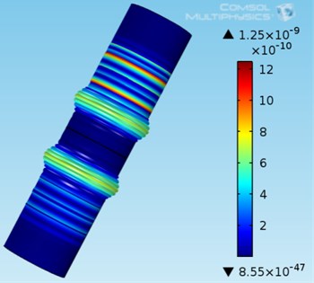
The colour bar on the right indicates that different colours represent different displacement sizes. It can be seen clearly from the figure that after the mode guided wave propagates through the crack defect on the inner wall of the barrel, two modes of guided wave are produced, one before the other. It shows that the guided wave has the phenomenon of mode conversion here. By the colour contrast of the lines in the figure, it is found that most of the excited guided waves pass through the defect and are transmitted into two modes of guided wave, i.e. and , and a small part is reflected after passing through the defect. For the same two modes of guided waves, it shows that there are defects in this barrel [4].
3. Sensitivity analysis of 2 and mode guided waves for forest detection
Choosing a suitable value to reflect the changes in the propagation process of different modes of ultrasonic guided waves under different radial sizes of defects is helpful to judge the sensitivity of guided waves to the radial sizes of the barrel. The radial dimensions of this section are respectively 1 %-10 % of the wall thickness of the barrel, and the defects are 200 mm away from the exciting end of the barrel.
3.1. mode guided wave propagation characteristics analysis
After solving and calculating the propagation characteristics of guided waves in the barrel under different radial size defects, observe the influence of different radial size on the propagation characteristics of guided waves, take a point on the inner wall of the excitation end of the barrel as the observation point, and the axial displacement of the observation point of the barrel under different radial size is as shown in the Fig. 2.
Because the maximum amplitude of the primary echo of the crack can be used to represent the change of the propagation characteristics of the guided wave, the maximum amplitude of the primary echo of the defect can be selected as the reference value for crack depth detection. However, considering that the amplitude of the excitation signal of each guided wave may be different when the guided wave is used to detect the barrel for many times in the actual experiment, which causes the instability of the amplitude of the echo signal and affects the analysis and judgment of the radial size results of the barrel defects. If the ratio of echo signal amplitude to excitation signal amplitude is used as the research reference object, this problem can be solved well. Therefore, the ratio of the maximum amplitude of the echo signal to the maximum amplitude of the excitation signal is defined as the echo coefficient, which reflects the influence of the defect scale change on the guided wave propagation process [5].
Fig. 2Axial displacement of received signals with different radial dimensions
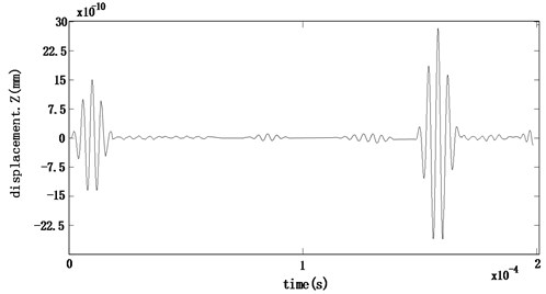
a) 5 % barrel wall thickness
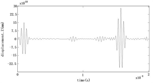
b) 10 % barrel wall thickness
Using the post-processing function of the finite element simulation software, it can be seen that when the radial size is 10 % of the barrel wall thickness, the maximum amplitude of the echo of a defect is about 1.1278×10⁻¹⁰ mm, while the maximum amplitude of the excitation signal is about 15×10-10 mm, and the echo coefficient is 7.52 %. In order to find out the relationship between the radial size of the defect and the echo coefficient of the defect accurately, it is necessary to find out more data of the maximum amplitude of the primary echo of the defect. Using the same method, it can be obtained that the radial size is 1 %-10 % of the barrel wall thickness, and the maximum amplitude and echo coefficient of the echo of the primary defect are shown in Table 1.
Table 1Echo coefficients corresponding to different crack depths
Relative ratio of radial dimensions (%) | Maximum echo amplitude of primary defect (mm) | Echo coefficient (%) |
1 | 8.5428×E-12 | 0.57 |
2 | 2.2153×E-11 | 1.48 |
3 | 3.1733×E-11 | 2.12 |
4 | 4.1108×E-11 | 2.74 |
5 | 5.0880×E-11 | 3.39 |
6 | 6.4352×E-11 | 4.29 |
7 | 7.6653×E-11 | 5.11 |
8 | 8.9412×E-11 | 5.96 |
9 | 1.0259×E-11 | 6.84 |
10 | 1.1277×E-10 | 7.52 |
From the case of different crack depth in the table, the maximum amplitude and echo coefficient of the primary echo of the defect corresponding to the change. The relationship between radial dimension and echo coefficient can be established to observe the relationship between them. Set each data point in the table in the coordinate system with radial dimension as the ordinate and echo coefficient as the abscissa, and use MATLAB data analysis software to fit the data points, and establish the curve as shown in Fig. 3.
Fig. 3Echo coefficient and defect size change curve
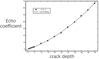
It is found from the graph that each data point satisfies the relation of quadratic polynomials. The equation of quadratic polynomials is as follows: . Where, represents the ratio of defect size to barrel thickness, and represents the echo coefficient of primary echo. The fitting results show that the fitting degree of the curve is 0.99, approximately 1. Both of them meet the above relationship.
3.2. mode guided wave propagation characteristics analysis
In this section, mode guided waves are excited at one end of the barrel by changing the excitation mode. The ratio of the maximum amplitude of mode ultrasonic guided wave echo signal to the maximum amplitude of excitation signal is defined as echo coefficient, which reflects the influence of wear defect radial scale change on guided wave propagation. Using the same method, we can respectively obtain the maximum amplitude and echo coefficient of the echo ( mode) of the primary defect with the radial size of 1 %-10 % of the barrel wall thickness, as shown in Table 2.
Table 2Echo coefficients corresponding to different crack depths
Relative ratio of radial dimensions (%) | Maximum echo amplitude of primary defect (mm) | Echo coefficient (%) |
1 | 8.5428×E-12 | 0.21 |
2 | 2.2153×E-11 | 0.22 |
3 | 3.1733×E-11 | 0.24 |
4 | 4.1108×E-11 | 0.26 |
5 | 5.0880×E-11 | 0.29 |
6 | 6.4352×E-11 | 0.31 |
7 | 7.6653×E-11 | 0.35 |
8 | 8.9412×E-11 | 0.40 |
9 | 1.0259×E-11 | 0.46 |
10 | 1.1277×E-10 | 0.54 |
Using MATLAB data analysis software to fit the simulation experiment data, the following relationship can be obtained: . Where, represents the ratio of defect size to barrel thickness, represents the echo coefficient of mode guided wave primary echo. The fitting results show that the fitting degree of the curve is 0.99, approximately 1. Both of them meet the above relationship.
4. Conclusions
It is found that the change rate of echo coefficient of mode guided wave with the radial dimension of defect is faster than that of mode guided wave, and the echo coefficient of mode guided wave is relatively larger in each defect dimension, which makes the mode guided wave more affected by the error in actual detection. Small, relatively high detection accuracy. It can be seen that the sensitivity of mode guided wave is higher than that of mode guided wave for radial defects in barrel [5].
This conclusion is helpful for the next step of practical inspection. It is of theoretical significance to select the ultrasonic guided wave mode for the radial wear defect in gun barrel.
References
-
Rayleigh J. The Theory of Sound. Vols. 1 and 2, Dover Publications, New York, 1945.
-
Sun Xuewei, Li Fucai, Miao Xiaoting, et al. Ultrasonic guided wave propagation and damage identification in thick beam structures. Journal of Mechanical Engineering, Vol. 14, 2012, p. 5-14.
-
Lowe P. S., Fateri S., Sanderson R., Boulgouris N. V. Finite element modeling of the interaction of ultrasonic guided waves with coupled piezoelectric transducers. Insight, Vol. 56, Issue 9, 2014, p. 505-509.
-
Zheng Ming-Fang, Lu Chao, Chen Guo-Zhu, Men Ping Modeling three-dimensional ultrasonic guided wave propagation and scattering in circular cylindrical structures using finite element approach. Physics Procedia, Vol. 22, 2011, p. 112-118.
-
He Cunfu, Li Longtao, Wu Bin Circumferential ultrasonic guided waves in hollow cylinders. Journal of Mechanical Engineering, Vol. 40, Issue 8, 2004, p. 7-12.
About this article

This paper is supported by the research project of real-time prediction method of gun barrel residual life based on ultrasonic guided wave.
Thank the members of the project team for their help in the writing process of this article, especially the pertinent suggestions given by Professor Zhou Yuan and Professor Yin Zhuchen on theoretical guidance and later revision.
