Abstract
The design of an escalator should consider the safety factor as well as the light weight performance. In this paper, we analyzed the structure performance of the step of an escalator which was making of aluminum alloy materials. We did three simulations which related to the strength checking, rigidity checking and the pedal-bending experiment of the step of an escalator. Our results showed that the maximal deformation of a step was at its middle while the maximal stress was located at the support of the step where the weak part of the step is. Our results can be references for the light weight design of the escalator.
1. Introduction
An escalator in public area always undergoes high-load and long-term operations, and thus the design of an escalator prefers to the safety performance optimization [1]. However, the light weight design can guarantee the requirement of mechanical property of escalator as well as reduce the usage of raw material lowing the production costs. With the development of computer-aided analysis, the finite element has widely been used in the structural design for both mechanical and electromagnetic design [2]. Finite element-based design which acquires the mechanical characteristics without experiment can extremely reduce the development cycle and the design costs [3, 4]. In this paper, we focus on the analysis of the mechanical property (bending, strength and rigidity) of the step of an escalator with finite element method. Our result can be used as a reference for the validation of the escalator design.
2. Modelling
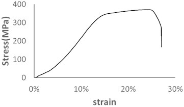
In this design, we adopted the 2A11 aluminum alloy as the raw material for the step of an escalator and the material parameters are shown in Table 1. To achieve an accurate physical property of the material for the simulation, we carried out the stretching experiment of the aluminum alloy sample (Fig. 1) [5].
Fig. 1Strain-stress curve for 2A11 aluminum alloy
The outline of the escalator is shown in Fig. 2 are the length, width and height of a step of an escalator (Fig. 2(a)). Fig. 2(b) is the tooth of a step. The modelling of the step of an escalator is completed with Catia V5 (Dassault Systèmes, France) which is shown in Fig. 3. The primary data of the modelling which is based on [6] is shown in Table 2. We used the optimization tool to optimize the parameter of the step and the response point was located at the junction of the step and the shaft. There existed stress concentration at the response point and the mass, deformation and the stress were 18.802 kg, 1.75 mm and 323.56 MPa, respectively. The optimized parameter of the response point is shown in Table 3. Based on the response point; we achieved the candidate points for the re-modelling of the step of an escalator. The parameters of the candidate points are shown in Table 4. We used the parameter of point1 for the re-modeling of the step to which the mass can be reduced 22.72 %.
Table 1The property of adopted material
Material | Temperature [°C] | Poisson’s ratio | Tensile yield strength [MPa] | Young’s modulus [GPa] |
2A11 | 24 | 0.33 | 370 | 72 |
Fig. 2The outline of the escalator
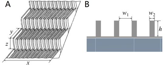
Fig. 3Modelling of a step of an escalator
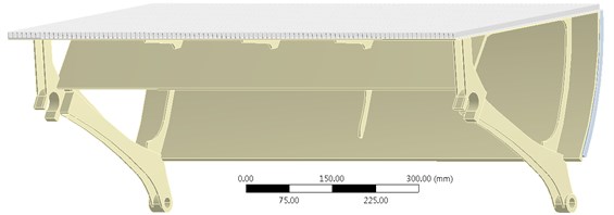
Table 2Primary data of the modelled step of an escalator
Parameter | Range | Primary selection | Unit |
Tooth height () | ≥10 | 10 | mm |
Tooth width () | 5-7 | 5 | mm |
Space between teeth () | 2.5-5 | 5 | mm |
Thick of comb plate | 3-5 | 3 | mm |
Table 3The optimized parameter of the response point
Parameter | Tooth height | Tooth width | Space between teeth | Thick of comb plate |
Optimized size [mm] | 10.5 | 6 | 4 | 4 |
Table 4Parameters for candidate point
Point 1 | Point 2 | Point 3 | |
Tooth height [mm] | 10 | 10.282 | 11 |
Tooth width [mm] | 3 | 3.037 | 3 |
Space between teeth [mm] | 7 | 6.963 | 7 |
Thick of comb plate [mm] | 3 | 3.149 | 3 |
Mass [kg] | 14.53 | 14.781 | 14.867 |
3. Experiments
3.1. Strength checking
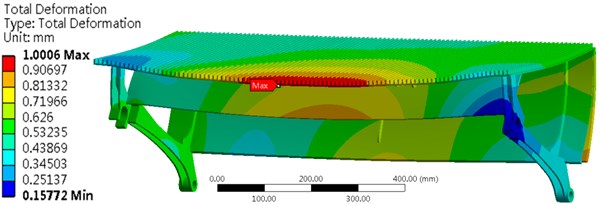
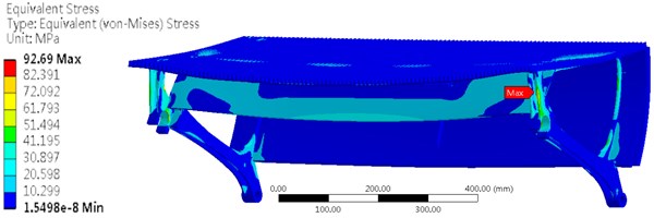
As is shown in [6], the step should have enough strength in the life cycle. Therefore, we did the strength checking for the step and a uniformly distributed load was exerted on the surface of the step. The junction area of the step was imposed a constraint which can fix the step along the direction of axis. The result is shown in Fig. 4. The maximum stress was 92.69 MPa which is located at the support of the step. This value is far less than the tensile yield strength and thus fracture or yield will not occur at this point.
Fig. 4Stress and deformation of the step with a uniformly distributed load
3.2. Rigidity checking
The rigidity checking experiment is conducted by exerting a force of 3000 N on a steel plate which is connected to the middle of the step (Fig. 5). The measure of area of the steel plate was 20 mm×30 mm and the thickness was 25 mm. The edge of the long side of the step is parallel to the side which is 20 mm long of the steel plate. The deformation of the step should be less than 4 mm. As is shown in Fig. 5, the maximum deformation is 0.675 mm occurring at the edge of the middle of the step. The maximum stress is 53.517 MPa which located at the support of the step.
4. Bending experiment
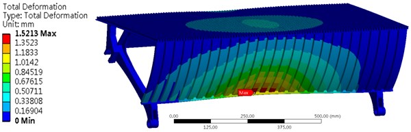
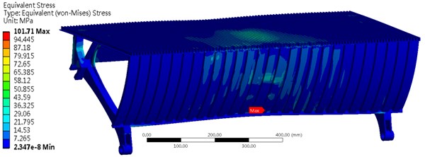
The bending experiment is to exert a force of 1500 N on a steel plate which is adhere to the arc part of the step. The area of the steel plate is circular with the measure of area is 25 mm2, and the steel plate and the arc part of the step should be tangent. The largest deformation of the arc part of the step should not exceed 3 mm. As is shown in Fig. 6, the maximum deformation is 1.52 mm which is located at the edge of the middle of the step. The maximum stress is 101.71 MPa which is located at the loading area of the force.
Fig. 5Stress and deformation of the step for the rigidity checking experiment
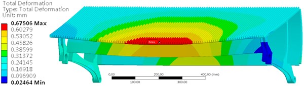
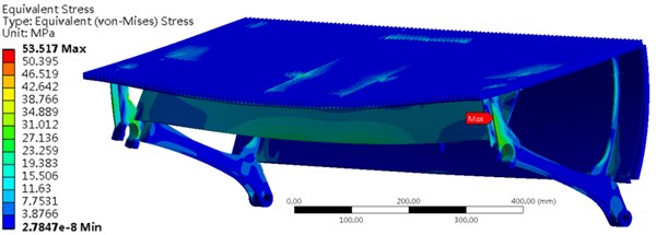
Fig. 6Stress and deformation of the step for the bending experiment
5. Conclusions
In this paper, we used the finite element analysis to conduct three simulations for the validation of the optimized structure of the step of an escalator. Our results show that the weak area is located at the support of the step while the largest deformation located at the edge of the middle of the step. Such a result can be a reference for the design and validation of a step. In the future, we will focus on the light weight deign of the escalator from the aspect of the stiffening ribs and the support plate of an escalator.
References
-
Al Sharif L. Topics in Escalator Step Design and Testing. Elivatori, 2001.
-
Mehul S., Shah D. B., Bhojawala V. Analysis of composite leaf spring using FEA for light vehicle mini truck. Journal of Information, Knowledge and Research in Mechanical Engineering, Vol. 2, Issue 2, 2012, p. 424-428.
-
Zhao J. C., Chen X., Zhao Z. Y. Performance evaluation and prediction of escalator structure using FEM-based analysis. Advanced Materials Research, Vol. 819, 2013, p. 59-64.
-
Park C. J., Gschwendtner G. Braking performance analysis of an escalator system using multibody dynamics simulation technology. Journal of Mechanical Science and Technology, Vol. 29, Issue 7, 2015, p. 2645-2651.
-
Yang Z., Deng B., Deng M., Sun G. A study on finite element analysis of electric bus frame for lightweight design. MATEC Web of Conferences, Vol. 175, 2018, p. 03049.
-
En B. 115-1-2008+ A1-2010 Safety of Escalators and Moving Walks. Construction and Installation, 2009.
About this article

This work is supported by the three levels of talent construction project of Zhuhai College of Jilin University.
