Abstract
Based on the STM32 library function, this design is developed a good docking with the engine, without changing the engine's original ECU. Only on the test bench, this design which connected to the device can enter the injection pulse width, so as to control the engine mixture concentration. Using this experimental device, the fuel adjustment characteristic experiment was completed on the existing engine test bed, which verified that the experimental device developed by this design had good adaptability in use. In this way, universities and research institutes can use this experimental device to easily complete the fuel adjustment characteristic experiment, and can also provide a convenient tool option for the calibration and optimization of the engine pulse spectrum.
1. Introduction
The initial gas mixture supply method of the gasoline engine is a carburetor, and the carburetor modulates the gas mixture required by the engine according to the operating conditions of the engine. The way to adjust the concentration of the mixed gas by the fixed throat carburetor is to fix the throttle opening at a fixed speed, adjust the main metering hole, and change the fuel supply to obtain the fuel adjustment curve [1-3]. Relatively speaking, the carburetor engine can relatively easily complete the fuel adjustment characteristic experiment. One of the main defects of the carburetor's fuel supply method is that the throat in the intake pipe is narrow, resulting in high air resistance and low output power. Secondly, the mixed gas distribution is uneven, which has an impact on engine performance [4-9]. Due to the increasing awareness of energy conservation and environmental protection, people realize that the greenhouse effect is becoming more and more serious, and the problems of automobile fuel consumption and exhaust pollution have attracted more and more attention. In addition, countries around the world continue to strengthen the control of vehicle engine exhaust emissions, and emission standards have become increasingly strict. In recent years, energy consumption and emissions have become increasingly serious. One of the main reasons is caused by the rapid development of various models of vehicles with small displacement gasoline engines as the main power source. Therefore, in order to control the emissions of small gasoline engines, people continue to develop new technologies and control the use of more precise electronically controlled injection technology.
2. Hardware circuit design
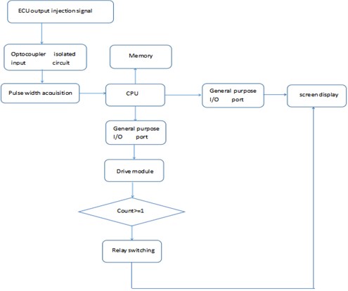
The main hardware integrated circuit of this design is composed of data acquisition module, fuel injection control drive module, relay switching experiment mode module, resistance display module, and manual input fuel injection pulse width and power module. When the control system is controlled by the ECU, the acquisition circuit collects the fuel injection pulse signal output by the ECU. After shaping and filtering, the signal is output to the single-chip microcomputer, and the single-chip microcomputer outputs the signal to the four-way drive circuit to control the fuel injection of the fuel injector. At the same time, the resistance display screen shows the fuel injection pulse width of the collected fuel injection pulse signal. Based on the collected fuel injection signal, the control system manually input the set fuel injection pulse width in the resistance display screen in the experimental state, and the single-chip microcomputer outputs the signal to the drive circuit to control the injectors spray sequentially. Finally, the fuel adjustment characteristic experiment is completed.
Fig. 1Experimental device control system
2.1. Main control unit CPU
The STM32F103x series of single-chip microcomputers are mainly based on the ARMCortex-M3 processor and are produced by ST. The architecture has a 32-bit standard processor. Microcontroller systems, automotive electronic control systems, industrial control systems, wireless networks, etc., all belong to the field of embedded applications that require high power consumption, system cost, and development capabilities.
2.2. Power circuit
The power supply circuit is shown in Fig. 2. The power circuit designed in this subject is divided into two parts, one is to convert the external 12V power supply to 5 V, and the other is to convert 5 V to 3.3 V. Because the acquisition circuit requires 5 V power supply, the HTC2576 monolithic integrated circuit is used. The HTC2576 is a step-down switching regulator with a step-down switching function. Its function is to convert a 12 V voltage to a 5 V output voltage. The other is to convert 5 V to 3.3 V. Because the power that the single-chip microcomputer can withstand is 3.3 V, we convert 5 V to 3.3 V through LD1117 to obtain the voltage required by the single-chip microcomputer.
2.3. Fuel injection signal acquisition circuit
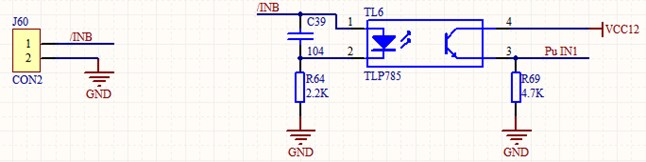
The fuel injection signal acquisition circuit is shown in Fig. 3. The injector is connected to the J60 terminal. Because the injection signal voltage is high, it is easy to interfere with the signal from the main control unit. Therefore, the optocoupler device TLP785 should be used for isolation. The 1 pin of the comparator rises to the high level and is output through the 3 pin of the comparator. When the fuel injection signal is turned off, the comparator 1 pin is low and is output by the comparator.
Fig. 2Power circuit
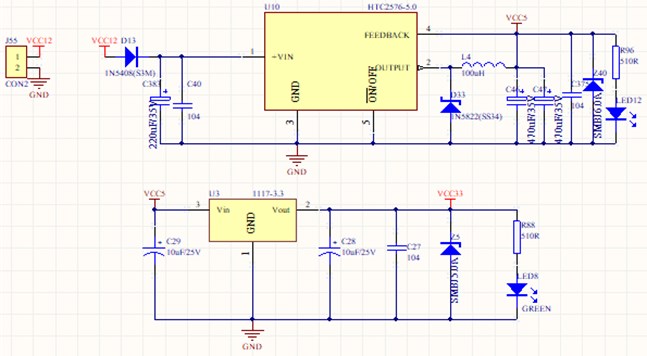
Fig. 3Fuel injection signal acquisition circuit
2.4. Fuel injection drive circuit
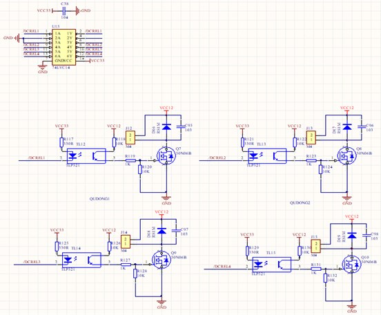
The engine of this experimental object uses the internal resistance of the injector to be 3 ohms and the power is 12w. The MOSFET is used to control the on and off of the injector. The drive circuit has a total of four paths, which are sprayed in the order of 1324. The fuel injection drive circuit is shown in Fig. 4. The circuit uses TLP521 optocoupler isolator, which is composed of infrared light emitting diode and NPN silicon phototransistor. The signal is input from pin 2 of TLP521. When the input signal is at a high level, pins 1 and 2 of the optocoupler isolator form a voltage difference, and the optocoupler isolator is turned on, so that the MOS transistor Q7 is turned on. The J12 terminal is connected to the fuel injector on the engine, and the MOS tube controls the fuel injector to be turned on and off. The capacitor C95 and the diode D16 in the circuit are connected in parallel to reduce the ripple of the MOS tube and prevent interference. When the low level is input, the optocoupler isolator is cut off and the MOS tube is disconnected, thereby controlling the injector to stop injection.
2.5. Switching relay control circuit
Three pins of J41 terminal, one end is connected to the fixed contact of the relay, one is connected to the normally open contact, and the other is connected to the normally closed contact. After the circuit is energized, the normally closed contacts are connected, and the original fuel injection signal is collected to drive the fuel injection of the fuel injector. When you want to switch to the experimental circuit, the normally closed contact opens, the relay pulls in, and the normally open contact closes. Resistor R33 acts as a current limit, reducing the power consumption of the N-pole transistor. The role of diode D12 is to use it to absorb the larger back electromotive force generated when the relay is energized or disconnected, so that the relay plays a role of freewheeling.
Fig. 4Fuel injection drives circuit
2.6. Resistive display circuit
The resistance display circuit is shown in Fig. 5. This experiment uses VGUS serial screen. The VGUS serial screen and the MCU are connected through the serial port. The 0×80 and 0×81 commands are used to control and set related functions. The display and touch related functions are realized by the 0×82 and 0×83 commands.
Fig. 5Resistive display circuit
3. The engine performance
3.1. Equipment
In order to verify the effectiveness of the developed fuel adjustment characteristic experimental device, the developed device was connected to the engine test bed for bench application test. The test used “modern” gasoline engine test bench, “chengbang” engine measurement and control system, exhaust gas analyzer and other equipment. The engine measurement and control system can measure the engine speed, power, torque, fuel consumption rate, oil and gas door opening, water temperature, oil temperature and atmospheric temperature. The exhaust gas analyzer can measure the concentration of CO2/CO/CH/NOx and O2 and give the excess air coefficient.
3.2. The experiment method
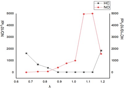
When the engine is running at a fixed throttle opening value, the acquisition module collects the injection signal, reads the injection pulse width value, converts the speed, and controls the four-way injector to inject fuel. Then the relay is switched, referring to the collected fuel injection pulse width and rotation speed, the fuel injection pulse width value is manually input in the resistance display screen. The excess air coefficient of the exhaust gas analyzer is changed at equal intervals as far as possible, and the data is recorded. The test curve is shown in Fig. 6. After the excess air coefficient gradually increases, the HC content gradually decreases. The contents of CO2 and NO both increase first and then decrease. The excess air coefficient is around 1-1.1, and CO2 and NO reach the highest point. Among them, NO reached a maximum point when the excess air coefficient was 1.1-1.13, and then fell sharply. The downward trend was obvious.
Fig. 6Engine fuel adjustment characteristic curve
4. Conclusions
In this paper, an experimental device for fuel adjustment characteristics connected to a gasoline engine is developed. One end of the input collection terminal of the experimental device is connected to the negative electrode of the connector of the engine injector; the other end is connected to the ground of the power supply. The output end is connected to the engine injector. Using this device, the engine fuel adjustment characteristic test was completed, and the curves of engine power, economy, and emission with fuel injection volume were verified, which provided a convenient option for universities to develop fuel adjustment characteristic curve experimental courses. The experimental device developed by this design can be mainly used in fuel adjustment characteristic test courses set up by colleges and scientific research institutes, which can enable students to have a deeper understanding of the influence of fuel injection volume changes on engine performance.
References
-
Zi K., Deng B. Q. Engine Principle. Tsinghua University, Beijing, 2014.
-
Deng B. Q., Jia Y. C., Yang Z. Development and utilization of experimental device for gasoline engine fuel adjustment characteristics. IOP Conference Series: Earth and Environmental Science, Vol. 227, 2019, p. 032022.
-
Wang L. B., Ge Y. Explore automotive pollution and emissions technologies Journal of Jiaozuo University, Vol. 3, 2015, p. 72-74.
-
Liu J. H., Wu S. F., Li H. Q., Su T. X. Analysis of emission factors of universal small gasoline engine. Small Internal Combustion Engine and Vehicle Technology, Vol. 44, Issue 3, 2015, p. 79-83.
-
Zhao Y., Yang M. Analysis of emission factors of universal small gasoline engine. Electromechanical Product Development and Innovation, Vol. 25, Issue 5, 2012, p. 71-73.
-
Shi A., Xu G., Shi J. Research and analysis of engine combustion based on independent test system. 3rd International Conference on Engineering Technology and Application, 2016.
-
Li J., Wang Q. Control system of trajectory tracking of discretely-actuated manipulator based on computed torque method. Journal of Intelligent and Fuzzy Systems, Vol. 38, Issue 6, 2020, p. 7575-7584.
-
Guo Y., Hou Z., Liu S., et al. Data-driven model-free adaptive predictive control for a class of mimo nonlinear discrete-time systems with stability analysis. IEEE Access, Vol. 7, 2019, p. 102852-102866.
-
Zhou L., Liang Y., Xu M. Simulation study on the impact of uneven fuel injection of each hole of the diesel engine injector on the combustion process. IOP Conference Series Materials Science and Engineering, Vol. 782, 2020, p. 042008.
About this article

Zhuhai Vehicle Engineering Dominant Discipline Funding.
