Abstract
Injection systems of modern commercial vehicle power units are still a frequent topic for development engineers in terms of durability and reliability. Therefore, the content of this study is just an investigation of the dynamic behaviour of high-pressure injection pipes of a four-cylinder combustion engine. The modal properties of the injection tubes are evaluated by experimental modal analysis (EMA). Another phase of the measurements is the sensing and analysing of the acceleration on each injection pipe during the engine speed ramp in the entire range of the speed spectrum. There was investigated the modal behaviour of the structure to the operational character of the excitation. The work includes a numerical model established by finite element method (FEM), where the boundary conditions correspond to the real installation of injection pipes from the measurement. The modal properties of injection pipes were primarily investigated through the numerical approach, several variants of pipe attachments were considered in simulations. Comparing the FEM results of different pipe attachments, the suitability of the clamp position with respect to the specific installation in the power unit from the measurement is discussed. From the evaluated results, it is possible to assume the dynamic behaviour of the high-pressure injection pipe in the power unit. Based on the performed analyses, the critical mode shapes of the injection pipes are described considering the engine operating condition. When the engine speed frequency and some pipe eigen frequency interfere together, it is undesirable state. In many cases, this leads to a crack initiation and subsequent damage of the injection pipes during the cyclic load. The presented results and conclusions in this study should improve the overall knowledge on high-pressure fuel pipes in terms of modal properties and its vibration behaviour during operating condition.
1. Introduction
In the last decade, diesel fuel injection systems have undergone considerable progress. From the point of view of tightening emission quotas, the great emphasis is still placed on the fuel mediation into the individual cylinders of the engine. The fuel must be atomized through modern injection systems under enormous pressure, often exceeding 200 MPa. Such high injection pressures cause significant stresses on functional parts of the fuel injection system, such as injectors and injection tubes especially.
When the engine is running, vibrations are constantly transmitted into whole injection unit, which is caused by the excitation forces from the combustion process. Other excitation sources result from the interconnection of the functional components of the entire power unit. Very important mechanical component is the crankshaft, which is quite massive engine part and has got many various pitfalls. The crankshaft function is often associated by the following undesirable characteristics: large moments of inertia, torsional, bending and longitudinal oscillations, misalignment and imbalance caused by manufacturing inaccuracies. All these features cause secondary excitation forces, which are transmitted via journals to the engine block and subsequently to all the adjacent functional parts of the power unit or the entire vehicle. Thus, induced vibrations are transmitted further via so-called transmission paths directly to mechanical parts of the injection system [1, 2].
To ensure the correct function of the injection unit, it is important to consider fuel supply to the individual cylinders when designing the injection fuel pipes. In injection systems, the injector nozzle is controlled by pressure pulses from the high-pressure fuel pump. By ensuring and retaining that the same amount of fuel is supplied to the cylinders, it is important that the injection pipes have the same length. This secures the proper fuel injection timing and the smoothness of the engine. To achieve the lowest pressure loss in the injection system, fuel pipes are designed for the shortest length. Because the high-pressure pump is in most cases driven by an engine timing mechanism, the direct distances from the high-pressure pump to the individual cylinders are different. To reach the same lengths of fuel injection pipes linking to the individual cylinders, it is necessary to consider the specific installation of the power unit in the vehicle during the design process. In many power units, thus the high-pressure pipes form different shaped loops which are connected by mutual fastening elements [3].
Based on mentioned principles and facts above, it is evident that injectors and high-pressure fuel pipes are the most stressed components of injection systems. The fuel injection pipe must meet high requirements in terms of service life, resistance to high fuel pressure and cyclic loads. There have been written many studies on the reliability, durability and mainly cracking of parts in injection systems.
By supplying fuel under high pressure from the pump, the injection tubes are elastically stressed and deformed, especially in the bent parts of the pipe. Due to the difference between intrados and extrados surface area of bends, the pipe tends to compensate effects of unbalanced forces due to the pressure applied to the walls of the pipes. In the literature, this phenomenon is referred to as the Bourdon effect. According to a study from [4], this phenomenon has the greatest impact on vibrations and disturbances in high-pressure injection pipes.
In the study described in [5, 6], the manufacturing process of the injection pipe head intended for Common Rail systems is analysed in detail. In the first phase of study, it was found that the optimal design of pre-form punch and two-stage heading process significantly contribute to the improvement of fatigue life. Furthermore, the influence of the autofrettage process on the residual stresses at the outer surface of the neck part of fuel pipe is investigated. The described findings show that the pre-form punch and heading process significantly reduce stresses in the folding area of the neck pipe. By using of the autofrettage process, the residual stresses in the pipe head area are reduced. The authors of this study declare that so called integrated process design, which includes the heading and autofrettage process, significantly increases the fatigue life of the neck part of the injection pipes. These are confirmed by performed fatigue tests results and according to the investigated structures by using scanning electron microscope technology.
The use of FBG sensors in dynamic characteristics evaluation of hydraulic pipes intended for the aerospace engineering is recommended according to studies [7, 8]. According to the presented findings, the use of FBG sensors has a high potential in terms of evaluating modal properties and detecting cracks in small and light-weight pipes.
Weidong L. with his colleagues [9] has present, that fluid-solid coupling model must be considered in FEM. According to their study, some deviations occur in mode frequencies, when the fuel weight is or is not considered in numeric simulation. This numerical modelling differences have greater impact mainly in lower eigen frequencies of fuel injection pipes, which are influenced most by operating engine speed. This statement is supported also by Junhong and his co-worker’s analyses [10]. One of the important conclusions from their comprehensive study clearly prove that low-frequency vibrations are crucial in fatigue life of high-pressure fuel engine pipes. Besides, in [11] has been briefly examined how much would the boundary condition change cause differences in mode shapes of the injection fuel pipes.
In this study, high-pressure injection pipes are investigated. These form the connection between the injection pump and the injector of a four-cylinder diesel engine. Numerical and experimental approaches have been used to diagnose modal properties of fuel pipes. In the content, several clamping variants of fuel pipes are mutual compared by FEM regarding the operational life condition of power unit. The EMA and operational modal analysis (OMA) results are assessed and discussed in text. This study brings more complex overview about high-pressure injection pipes in terms of modal properties, pipe clamping optimization and its dynamic behaviour under the operating engine conditions.
2. Description of the investigated problem
The problem is the cracking possibility of the high-pressure injection pipes located in the four-cylinder power unit. In that reason the influence of modal properties on the structural integrity of the investigated component was considered. The modal characteristics of the structure directly affects its service life throughout whole operational condition. Proper system design, regular inspection and maintenance during operation are the most important aspects of the structural integrity of the system. The excessive mechanical responses of the structural components are directly related to the modal nature of the system and the operational load. Once the structural component is dynamically loaded in frequency area of its eigen modal shape, the extreme mechanical responses are generated, which often leads to structural damages. Based on theoretical knowledge of vibration diagnostics, an association between defects occurrence and the speed frequency of the engine crankshaft was sought. In the diagnostic of the fuel injection pipes, the rotational speed and its harmonics of the crankshaft was considered as a main source of dynamic loading. First can be expressed:
where [Hz] is the rotational frequency of the crankshaft, [min-1] are engine revolutions per minute. However, in drive injection units, the most common source of vibration is the fuel combustion in cylinders. The combustion frequency equation thus follows from the functional principle of the four-cylinder engine:
where [Hz] is the combustion frequency and [–] is the number of the cylinders. In this case, twice the shaft speed of 82 Hz is the limit value. Ideally, no eigen shapes of the injection system components should lie around this critical frequency. Otherwise, the intersection of the eigen frequency with the combustion frequency would cause resonances, which are very undesirable and has a destructive character, as described above.
3. Clamps position optimization using FEM
The real modal properties of the investigated structure can differ fundamentally from the numerically calculated ones. There are basically several reasons for the difference. The basic error in the results from the numerical simulation of modal analysis can occur in a possibly inaccurate definition of material properties, inappropriately boundary conditions selection or insufficient mesh discretization. A large influence is then observed in the case of production inaccuracies. For example, inaccurate casting often leads to significant retuning of the structure dynamic properties.
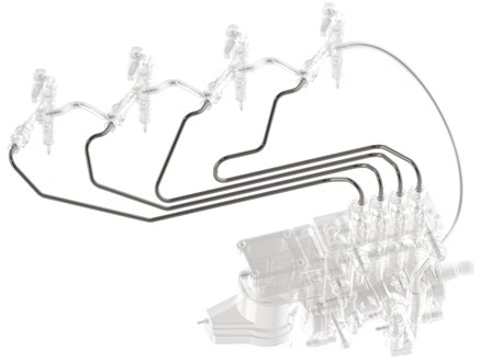
The numerical model according to which the calculation of the modal properties of the injection pipes was performed does not assume essential shape or construction deviations. A structural steel has been chosen in material properties according to the specification. The finite element mesh was created with tetrahedron elements by patch conforming method. The element size of 0.7 mm was used in the analysis, thus ensuring a sufficiently fine mesh with overall 1.6 million elements. The numerical model expects fixed boundary conditions on both sides: high-pressure pump side and engine side, see Fig. 1. It means, that whole six degrees of freedom were set to zero on pipe's head endings. In the initiation phase, there were no clamps considered in our computational model, in purpose to examine mainly the first eigen shape of the tubes and subsequently compare to our limiting combustion frequency. From the results is evident, the first eigen frequency of the injection pipes occurs at 82 Hz which is the same value as the twice of the rotational frequency in critical operational speed. Due to the engine operating speed range, it will be necessary to modify the first natural frequency of the fuel pipes to a higher value than our critical frequency of 82 Hz. From the basic equation of undamped oscillating system, the natural frequency can be expressed as follow [12]:
where [Hz] labels the natural system frequency, [N.m-1] its stiffness and [kg] its mass. In general, it follows from the equation that if we want to increase the eigen frequency of some structure, we can either increase its stiffness or reduce its mass. In the case of retuning the modal properties of the injection pipes, a stiffness modification appears to be the best option. In power units and in particular injection fuel systems, the clamps application for fixing injection pipes together is often used. It is an economically and especially time-efficient way to modify the modal properties of such a low-weighted structure quickly and efficiently.
The optimization process objective was mainly to increase the fuel pipe system stiffness, respectively retuning the first eigen shape of investigated structure to a higher frequency. Also, the clamps arrangement had to be structurally satisfying for the installation within the entire power unit. The main design variables of the numerical models were the clamps position, type and the number of clamps located on the four high-pressure fuel pipes. There were examined many variants of the clamps position in this study, some of them are depicted in Fig. 4.
Fig. 1Investigated injection pipes in power unit composition
4. Experimental approach
The modal properties investigation of the high-pressure injection pipes was performed on the off-road vehicle. The fuel pipes were mounted directly on the power unit. During the installation there was given a special importance that injection pipe fit to its original position and were mounted without any preload. The prestress of a structure has significant effect on its modal properties. This kind of structure fixing is in practice also called in-situ. The structure is fixed in real operating state conditions. The measurements considered two different experimental approaches in terms of excitation force. In the first phase, a standard EMA with a modal hammer was performed. In the second phase of the measurement, the dynamic behaviour of the structure during the operating state of the engine was investigated.
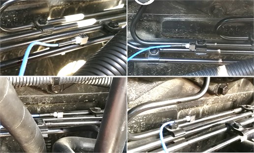
During measurements, a triaxial accelerometer was firmly glued sequentially to each injection pipe as it is depicted in Fig. 2. Through the PCB low-weight accelerometer, the frequency response of pipe to the impact force induced by the modal hammer and to the operating character of the excitation during the engine speed ramp was sensed.
Fig. 2Triaxial accelerometer glued on the injection pipes during measurement
4.1. The EMA by impact modal hammer
On each fuel tube separately, especially the eigen frequencies were investigated through the experimental approach. Since the fuel pipes has different geometric shape due to the motor installation, four original rod models of fuel pipes were created in software measurement environment, with predefined degrees of freedom. In the rod models, one degree of freedom was selected as the driving point, which recorded the response of the structure (glued accelerometer). This placement was chosen in a place outside the nodal point position of the first eigen shape of tube, which we are most interested in regarding of crack initiation.
Depending on the operator access to the fuel pipes, the excitation degrees of freedom were determined in different directions. In our case, the impact force was induced either in the axis – the transverse direction or in the axis – the vertical direction. The axis represented the longitudinal direction of the tube according to the location of the acceleration sensor. It was almost impossible performed a hammer hit in this direction. The force pulse induction into the individual excitation points was repeated five times to ensure a satisfying coherence and thus the most accurate results. The dependency between response and excitation in EMA is referred to as the frequency transfer function (FRF). According to [13], the FRF can be described as follows:
The FRF’s were evaluated from all measuring points, from which the natural frequencies of the fuel pipes were determined. In the results evaluation, the FRF example from one measuring point is depicted in Fig. 6. Since the injection pipes in the drive unit installation were clamped together during the measurements, the whole structure behaved as one unit, which was expected.
4.2. The OMA during the engine operation
Due to the validation of the natural frequencies of the injection pipes, a simplified variant of OMA was applied to verify obtained results from experimental modal analysis. The measurement was mediated during the real operation of the unloaded engine – gear disengaged. There was set around 4, 5-minute engine speed ramp in its full speed range up to 2 460 RPM. At the same time, the acceleration on each fuel pipe was sensed by a triple axis acceleration sensor to investigate excitation force effects in the operating state of the vehicle. On the multi spectra in Fig. 7, the eigen frequencies of high-pressure injection pipes are identified.
5. Results evaluation
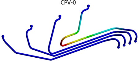
Using the experimental and computational approach has given more comprehensive knowledge of the investigated structure. From the modal analysis results follows, the original design of the fuel pipes composition without the clamping elements is not suitable for this off-road combustion unit. In Table 1, the investigated clamps position variants (CPV) are listed. The CPV-0 in the second column is the original variant without used clamps. It is clear from the results, when the assembling the injection pipes without clamping elements, the excitation frequency interferes with the first natural frequency of the injection pipe leading to fourth engine cylinder. The first mode shape of the unconstrained pipe is depicted in Fig. 3.
As already mentioned above, it is highly desirable to disturbed resonances in the first eigen shape. The solution was proposed by increasing the overall rigidity of the injection tube system through its interconnection. The aim was to select a suitable arrangement to reach a sufficient increase of the natural frequencies outside the dominant engine excitation. There are many clamps arrangement that could be considered. When choosing a suitable arrangement of pipes, the following aspects were considered in particular: retuning of dynamic properties, easy assembly, and availability of used components.
Table 1Eigen frequencies [Hz] of examined clamps position variants by FEM
Mode | CPV-0 | CPV-1 | CPV-2 | CPV-3 | CPV-4 |
1 | 82 | 93 | 88 | 97 | 98 |
2 | 87 | 164 | 156 | 159 | 151 |
3 | 96 | 189 | 209 | 231 | 211 |
4 | 99 | 234 | 221 | 248 | 230 |
5 | 128 | 236 | 259 | 317 | 274 |
6 | 141 | 267 | 267 | 331 | 325 |
7 | 142 | 281 | 312 | 420 | 354 |
8 | 152 | 302 | 326 | 458 | 391 |
Fig. 3The 1st eigen shape of the fuel pipe
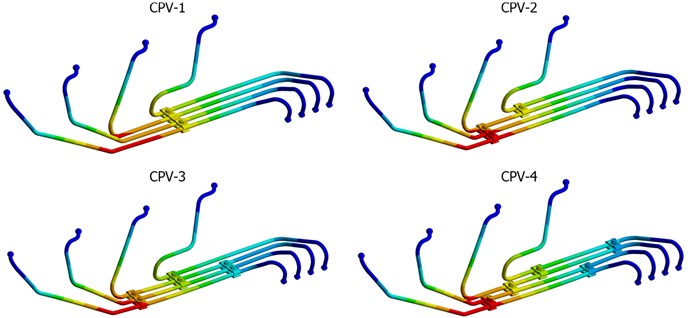
The Fig. 4 shows only some selected variants that have been solved. The individual CPV’s are designated as CPV-1 to CPV-4. The variant labelled as CPV-4 was chosen as suitable for our drive unit arrangement, five standard clamps were used for its fixing. The first critical natural frequency of clamped pipes in the CPV-4 variant is 98 Hz, which was increased by almost 20 % compared to the original pipe arrangement without any fixing elements. The retuning of the structure can be stated as sufficient. There are expected no major interferences between first eigen frequency and the engine combustion frequency. Besides of this, on Fig. 5 is shown first eigen shape for each clamps position variant. Only slight differences can be seen according to the colour scaling in eigen shapes, but especially the frequency values matter.
Fig. 4Clamps position variants
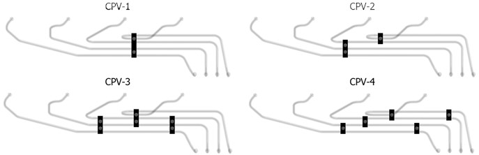
Fig. 5Eigen shapes of the first mode from investigated CPV’s
Numerical simulations were subsequently validated through technical experiment. In Table 2, the experimental and numerical results for CPV-4 are compared between each other. The deviation between FEM and measurement is at most in units of Hz.
Table 2Comparison of eigen frequencies [Hz]
Mode | MEAS | FEM | Difference [%] |
1 | 99 | 98 | –0,9 |
2 | 160 | 151 | –5,6 |
3 | 211 | 211 | 0,4 |
4 | 224 | 230 | 2,6 |
5 | 282 | 274 | –2,7 |
6 | 327 | 325 | –0,7 |
7 | 349 | 354 | 1,3 |
8 | 382 | 391 | 2,4 |
As an example of evaluating results from EMA, the FRF and the coherence from a specific measuring point are shown in Fig. 6. The characteristic curves are depicted in the frequency range up to 400 Hz, which in our case sufficiently retains the key natural frequencies of the injection pipes. FRF is a complex function and always includes both phase and amplitude at the same time. In our case, the FRF is converted into real and imaginary part. The figure can clearly identify seven natural frequencies. The natural frequency occurs if the real part acquires zero values and at the same time a peak occurs on the imaginary component. The eighth natural frequency at this measuring point and direction was not dominant and thus indistinct.
Coherence during the measurement was at a satisfied level. The decrease in the low frequency range is caused by the high-pass filter set up. It was set due to the sensor frequency measuring range. Other significant decreases are caused by strong antiresonances, which reduced the signal amplitudes to the white noise level.
Fig. 6Coherence, real and imaginary part of FRF in chosen measuring point
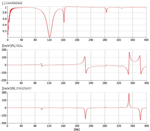
Fig. 7The acceleration multi spectra in X, Y and Z direction
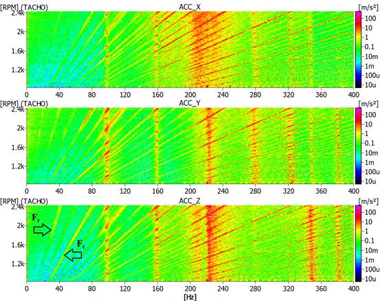
The Fig. 7 shows multi spectra from a simplified OMA analysis. The results of the acceleration measurement performed at one of the measuring points are depicted. Below each other, multi spectra for individual measured directions are displayed in , and direction.
Several basic signal components can be seen in the spectra. The basic engine excitation components labelled with arrows and , as well as their other higher harmonic multiples are obvious in Fig. 7. When the excitation frequency components intersect the individual eigen frequencies of the injection pipes, a local increase of the acceleration occurs at these frequencies. Intersections are then clearly visible in described spectra. The results of this measurement verified and confirmed the presence of already detected mode shapes from EMA. There is no intersection of the eigen frequencies of the tubes with the second order of rotational frequency, which was the objective of this study.
6. Conclusions
As described in text, the modal properties diagnostics is essential in terms of reliability and fatigue life of high-pressure fuel pipes. In this paper, the first mode shape of pipe is assessed as the most important one. From early modal analysis followed, that first natural frequency of the unconstrained tube lies at 82 Hz. The critical frequency of 82 Hz excited from combustion engine interferes with the first natural frequency of the fuel pipes. To eliminate this undesirable resonance, the several clamps position variants were proposed and examined by FEM.
A sufficient change in natural frequencies were achieved, where the pipes were connected through five simple clamps. This variant was labelled as CPV-4. The first natural frequency of the injection pipes in variant CPV-4 was increased by almost 20 % compared to the original design of CPV-0.
The accuracy of the computational model was validated by a technical experiment. The EMA as well as a simplified variant of OMA was performed. Although the computational model did not include all possible influences, like interior fuel pressure or fuel weight. This numerical model has a good agreement with measurement. Due to very good efficiency of the model, there was no reason for increasing of model level. For the most important first natural frequency of the injection pipes, the difference between the experimental and computational approach was less than 1 Hz.
References
-
Drápal L., Novotný P. Torsional vibration analysis of crank train with low friction losses. Journal of Vibroengineering, Vol. 19, Issue 8, 2017, p. 5691-5701.
-
Kučera P., Píštěk V. Torsional analysis of the engine computational model. Vibroengineering Procedia, Vol. 16, 2017, p. 25-28.
-
Stone R. Introduction to Internal Combustion Engines. 4th ed., Palgrave Macmillan, Basingstoke, 2012.
-
Kang J., Hu H. Vibration detection and diagnosis for high-pressure fuel pipe of diesel engineer. International Conference on Information Acquisition, Proceeding, 2004.
-
Bae J., Kim M.-S., Song M.-J., Jung S.-Y., Kim Ch. A study on optimal design and fatigue life of the common rail pipe. International Journal of Precision Engineering and Manufacturing, Vol. 12, Issue 3, 2011, p. 475-483.
-
Bae J., Kim Ch. A study on integrated design for improving fatigue life of common rail pipe considering stress concentration at complex shape. Journal of Mechanical Science and Technology, Vol. 28, Issue 9, 2014, p. 3617-3627.
-
Huang J., Zhou Z., Zhang L., Chen J., Ji Ch., Pham D. T. Strain modal analysis of small and light pipes using distributed fibre bragg grating sensors. Sensors, Vol. 16, Issue 10, 2016, p. 1583.
-
Wang Z., Liu M., Qu Y., Wei Q., Zhou Z., Tan Y., Hong L., Song H. The detection of the pipe crack utilizing the operational modal strain identified from fiber bragg grating. Sensors, Vol. 19, Issue 11, 2019, p. 2556.
-
Weidong L., Junhong Z., Jian W., Zhexuan X. Reliability analysis on high-pressure fuel pipe of diesel engine. International Conference on Mechanics and Mechatronics Research, 2016.
-
Junhong Z., Weidong L., Jiewei L., Yongbo Q., Yi Y., Tianyi Z. Failure analysis of a high-pressure fuel pipe of engine. Engineering Failure Analysis, Vol. 103, 2019, p. 70-81.
-
Patil Ch. K., Askhedkar R., Girase S. B., Shrigandhi G. D., Modal analysis of high-pressure fuel injection pipe for a DV-10 V Diesel engine. International Journal for Research in Engineering Application & Management, Vol. 4, 2018, p. 60-64.
-
Blevins Robert D. Formulas for Natural Frequency and Mode Shape. Krieger Publishing Company, USA, 2001.
-
Frankovský P. Using Modal Analysis for Vibrating Diagnosis Machinery. Technical University of Kosice, Faculty of Mechanical Engineering, 2011.
Cited by
About this article

The research leading to these results has received funding from the Specific research on Brno University of Technology FSI-S-20-6267 and project TN01000026 granted by Technology Agency of the Czech Republic. The authors gratefully acknowledge this support.
