Abstract
We present a study of the nonlinear dynamics of charged microparticles in a linear electrodynamic trap at normal pressure and temperature. In this work, will be considered a mathematical modeling of the nonlinear dynamics of a microparticle under viscous friction conditions, as well as experimental confirmation of theoretical results. Based on theoretical and experimental findings, we propose an innovative method for determining charge, mass and size of a certain microparticle localized in the linear electrodynamic trap.
Highlights
- The trajectories of charged microparticles trapped in a field of an electrodynamic trap form a closed two-dimensional orbits, called extended orbits.
- The shape and size of each extended orbit depends on the size, mass and charge of the object forming this orbit.
- A non-destructive method for assessing the physical characteristics of a single microparticle is proposed.
- The proposed method has been successfully tested experimentally.
1. Introduction
Mass and size are important parameters of any matter, definition of these parameters has a great interest in scientific community. There are many instruments for measuring particle mass, ranging from electronic weights to mass spectrometers; to determine size, there are many instruments and methods as well, from classical optical microscopy to correlation methods of dynamic light scattering. All these methods are good in their field, but they do not allow a simultaneous measurement of the mass and size of a particular object, all existing methods do not imply further work with a certain particle, which parameters are measured. Microparticles are a class object, where measurement of mass of a single particle is rather difficult, they are too large for mass spectrometry and too small for classical weighing. In turn, we propose a non-destructive method for determining mass, size, and also a charge, of a certain microparticle, based on effects of nonlinear dynamics of a charged object trapped in an alternating electric field of an ion trap.
2. Nonlinear dynamics model
Ion traps appeared in the second half of the 20th century and now are widely applied in fields of mass spectrometry [1, 2], frequency standards [3, 4] and quantum computing [5, 6]. Primarily, quadrupole ion traps are used in a vacuum environment where friction of a localized particle is either absent or insignificant. However, the study of the dynamics of a localized particle under friction has become popular; dissipative forces can be provided by a laser cooling or an atmosphere of buffer gases. Friction forces, in this case, can stabilize the movement of a localized object, however, under certain conditions of an alternating electric field, localized object parameters and friction forces, the effects of nonlinear dynamics can appear. The nonlinear nature of the dynamics of charged microparticles in a linear electrodynamic trap can be described by the following differential equations of motion [7]:
where , are radial positions in the trap, is dimensionless time, is acylating electric force parameter, is damping parameter, is particle velocity module, is amplitude of alternating trap field, is frequency of alternating trap fields, is particle charge, is particle radius, is particle mass, is trap geometric parameter, is air dynamic viscosity.
Eqs. (1) describe the coordinate of a charged particle in a plane perpendicular to the axis of the linear trap. It should be noticed that parameter is determined only by the size and mass of the particle, when parameter is related both to the charge and mass of the particle, and to the amplitude of the alternating field. Solving Eq. (1) by numerical methods with respect to the , parameters, it is possible to obtain both normal trajectories and various versions of extended orbits [8, 9]. In this paper, we focus on the extended orbits “Diamond”.
Studying the mathematical model of extended “diamond” orbits, a direct correlation between the shape and size of the orbit and the modeling parameters was revealed. The value of the parameter is proportional to the size and shape of the expanded orbit, while the parameter of the dissipative forces is inversely proportional only to the size of the orbit. An increase in the value of the parameter leads to a change in the shape of the trajectory from rounded to more angular. Passing to the physical meaning of the parameters and , assuming that the charge, mass and size of the localized microparticle remain constant over time (), changing the parameters of the system is possible only with a change in the amplitude of the alternating field (which is directly proportional to the parameter ). Separately, it should be noticed a fact that only one parameter can be brought into correspondence with only one parameter , where a transformation from a normal trajectory to an extended “diamond” orbit occurs. The border between normal and extended orbits is strict and sharp [8, 10].
3. Experimental implementation of extended “diamond” orbits
An experimental localization of charged microparticles was held on a simple quadrupole linear electrodynamic trap with four cylindrical electrodes. Localization was performed at normal atmospheric pressure and air temperature, where the dynamic viscosity of air is 18.1×10⁻⁶ Pas; the distance between the diametrically opposite cylindrical electrodes (geometrical parameter of the trap) is 22 mm.
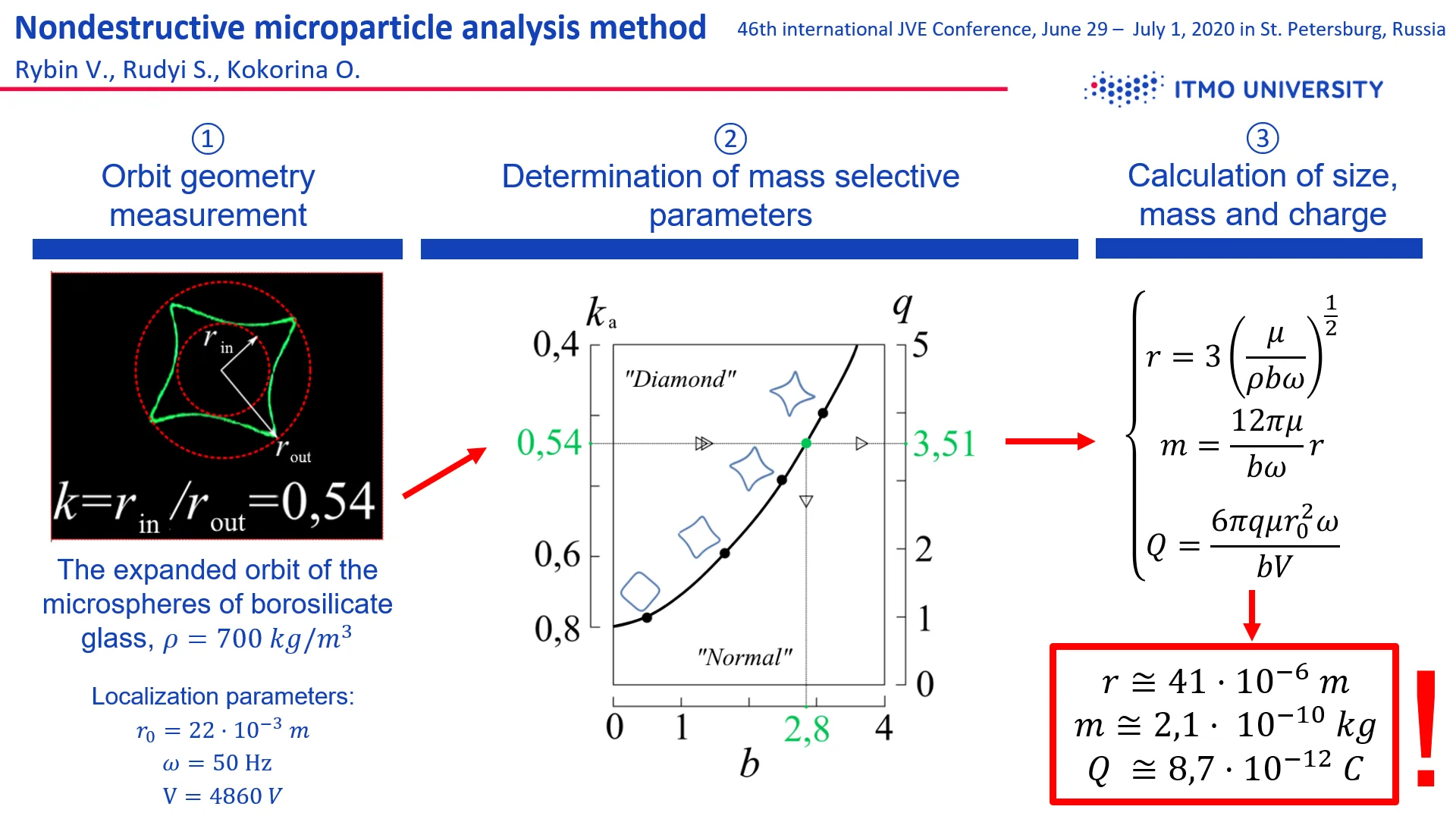
An experimental localization of borosilicate glass microspheres with a dispersion of sizes from 20 to 100 μm with an average density of 700 kg/mwas implemented. Extended orbits of certain microspheres were obtained, for example, the extended “diamond” orbit shown in Fig. 1 was obtained with the power supply of the trap 4860 V.
Fig. 1A real extended “diamond” orbit of borosilicate glass microspheres at V = 4860 V; with inscribed rin and described rout circles, the angular coefficient is ka= 0.54
As was predicted by theoretical calculations, the opening point of the extended orbit occurs sharply at a certain trap supply voltage for each individual localized particle, a direct correlation of the increase in the “angularity” of the extended diamond orbit with increase in supply voltage amplitude was also confirmed. As was determined in practice, at equal external conditions of localization, the opening point of the extended “diamond” orbit, as well as the initial angularity of the orbit, are individual for each localized object. From this we can conclude that the opening point and the initial shape of the extended orbit for each particle depend solely on their physical characteristics, and more specifically, on charge, mass and size.
4. Study of microparticle parameters
Summarizing the theoretical and experimental results, we present a method for determining the physical parameters of a certain microparticle localized in linear electrodynamic trap at normal pressure and temperature. The proposed method is based on a numerical measurement of the angularity of the extended “diamond” orbit, followed by a comparison of the angularity of the real orbit and its mathematical model described by Eq. (1). Such comparison makes possible to apply the parameters and of Eq. (1), strictly related to the charge, mass and size of the simulated object, to the real microparticle.
The angularity of the extended “diamond” orbit can be measured by the coefficient of angularity , as the ratio of the radius of the inscribed and described circles to the trajectory of a localized object (Fig. 1). Thus, the smaller the coefficient , the higher the angularity of the extended orbit. As shown by theoretical and experimental results, the angularity of the extended “diamond” orbit increases with an increase in the amplitude of the alternating field of the trap; therefore, the coefficient of angularity is inversely proportional to the parameter .
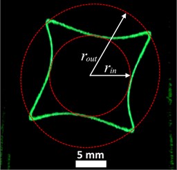
To compare the parameters and with the angularity coefficient , a diagram was constructed (Fig. 2) by solving Eq. (1) for parameters and . As mentioned earlier, we follow the assumption of the invariance of the charge, mass and size of a localized object through all localization process. In this case, for each certain particle, parameter is a constant, and coefficient is a function of the amplitude of the alternating voltage .
Fig. 2Diagram q-b-ka. Thick black line shows the border between normal and extended “diamond” orbits, blue color show typical shape of trajectories, green color indicates the coefficients for a microsphere of borosilicate glass, which extended orbit is shown in Fig. 1
Thus, knowing the amplitude of alternating trap field , when the extended “diamond” orbit opens; the dynamic viscosity of the localization atmosphere ; and calculating the initial angularity of the extended orbit , it is possible to determine the physical parameters of the localized object using Eq. (2). For a completely unknown object, it is possible to determine the charge and mass accurate to size of the object. However, possessing minimal information about the class of studied objects, for example, knowing the density or dispersion of sizes, performing a series of experimental measurements, it is possible to accurately determine the charge, mass and size of a certain localized particle:
where , are real numbers, is object’s density.
Using this method, we determined the physical parameters of the microsphere, which trajectory is shown in Fig. 1. After determination the angularity coefficient, we used the diagram in Fig. 3 to determine the parameters and . Further, using Eq. (2), the charge, mass and size of a certain localized microsphere were calculated ( 8.7×10⁻¹²) C, 2.1×10⁻¹⁰ kg, 41 μm). The microsphere size obtained is well agreed with the sizes measured by microscopy methods.
5. Conclusions
We have proposed an innovative non-destructive method for simultaneously measuring the charge, mass and size of a certain micro-object. The method is based on measuring the angularity of the extended orbit of microparticles localized in a linear electrodynamic trap under normal conditions. The proposed method was tested on glass microspheres, the measurement results match the range specified by the manufacturer, and in the range obtained by independent microscopic measurement of those microspheres.
References
-
Richard A. J. The 3D quadrupole ion trap mass spectrometer as a complete chemical laboratory for fundamental gas-phase studies of metal mediated chemistry. Chemical Communications, Vol. 14, 2006, p. 1469-1481.
-
Xiong C., et al. Mass, size, and density measurements of microparticles in a quadrupole ion trap. Analytical chemistry, Vol. 9, Issue 21, 2019, p. 13508-13513.
-
Werth G. Ion traps as frequency standards. IEEE Transactions on Instrumentation and Measurement, Vol. 34, 1985, p. 238-242.
-
Huntemann N., et al. Single-ion atomic clock with 3×10-18 systematic uncertainty. Physical review letters, Vol. 116, Issue 6, 2016, p. 063001.
-
Häffner H., Roos C. F., Blatt R. Quantum computing with trapped ions. Physics reports, Vol. 469, Issue 4, 2008, p. 155-203.
-
Bruzewicz C. D., et al. Trapped-ion quantum computing: Progress and challenges. Applied Physics Reviews, Vol. 6, Issue 2, 2019, p. 021314.
-
Le Clair B. P., Hamielec A. E., Pruppacher H. R. A numerical study of the drag on a sphere at low and intermediate Reynolds numbers. Journal of the Atmospheric Sciences, Vol. 27, 1970, p. 308-315.
-
Vinitsky E. A., Black E. D., Libbrecht K. G. Particle dynamics in damped nonlinear quadrupole ion traps. American Journal of Physics, Vol. 83, Issue 4, 2015, p. 313-319.
-
Rudyi S. S. et al. Outside localization around a toroidal electrode of a Paul trap. Journal of Physics Communications, Vol. 4, Issue 1, 2019, p. 015022.
-
Nasse M., Foot C. Influence of background pressure on the stability region of a Paul trap. European Journal of Physics, Vol. 22, Issue 6, 2001, p. 563.
Cited by
About this article

