Abstract
Gear mesh stiffness is an important indicator for condition monitoring of gears as its value has been found to decrease with initiation of crack. In the current study, the effect of crack propagation path on mesh stiffness has been investigated. Elliptical cracks with different values of semi major and semi minor axes have been considered with same values of crack lengths along these paths. ANSYS 19 software along with FRANC 3D has been used to model the gears with cracks induced. Structural analysis has been performed through Mechanical APDL. The values of mesh stiffness have been found to vary significantly with change in path of crack progression.
Highlights
- The effect of crack propagation path on mesh stiffness has been investigated
- Elliptical cracks with different values of semi major and semi minor axes have been considered with same values of crack lengths along these paths
- The values of mesh stiffness have been found to vary significantly with change in path of crack progression
1. Introduction
Mesh stiffness is an important parameter for dynamic analysis of mating gears. It is a time-varying factor and its value jumps interchangeably between two limits depending on the contact ratio of the mating gears, i.e., average number of pair of teeth in contact. Because of the changing nature of gear mesh stiffness, dynamic analysis of gears is essentially nonlinear. Mesh stiffness also depends on many other parameters such as the direction of applied load, tooth geometry, gear material specifications, profile error and faults, if any. Mating gear teeth are subjected to fatigue loading and are thus susceptible to crack generation. Generation and propagation of cracks significantly affect the value of gear mesh stiffness. Thus, gear mesh stiffness also acts as an indicator for condition monitoring of gears.
For healthy gears, mesh stiffness has been determined by several researchers over the last three decades [1, 2]. For calculation of mesh stiffness, gear tooth has been assumed to be a non-uniform cantilever beam subjected to bending, axial and compressive loads. Other factors considered in the determination of mesh stiffness include Hertzian contact and fillet foundation deflection. The values thus determined have been found to be in conformity with the values determined subsequently using numerical approach such as Finite Element Method (FEM). A substantial reduction in the values of mesh stiffness has been observed by Chaari et al. [3] when the stiffness was determined for gears with spalling and breakage using an analytical method. The values thus computed were compared with those obtained through FEM and were found to be in agreement [4]. Mesh stiffness for cracked gears have been determined in several other studies [5-11] considering these different parameters and varying crack length. Effect of varying crack depth and parabolic distribution was also studied [12]. The crack propagation depends upon the backup ratio, the ratio between the rim thickness and tooth height [13]. The initial crack angle also accounts for the crack propagation. The crack propagation path, for high backup ratios, tends to be smooth with a slight curvature and moves towards teeth. However, for low backup ratios, the propagation is through rim even with low crack propagation angles [14]. Both linear and parabolic crack propagation paths have been assumed by researchers for determination of gear mesh stiffness [12, 14].
From the above discussion, it is evident that effects of different parameters and varying crack length on gear mesh stiffness have been the main focus of earlier researchers. Though the path of crack propagation was considered in some of these studies, the effect of variation of path on gear mesh stiffness has not been studied in detail. Therefore, the effect of variation in crack propagation path on gear mesh stiffness has been investigated in the current study. Parabolic crack propagation paths with different geometries have been considered and the crack length has been gradually varied on these paths. The gear mesh stiffnesses for all these variations have been computed and a comparison among all these values concludes the paper.
2. Theoretical background and mesh stiffness formulation
Following the work carried out by earlier researchers [2-4], stiffness of gear pair in this work has also been determined considering the following factors: 1) tooth deflection due to applied external load assuming the tooth to be a cantilever beam; and 2) Hertzian contact deformation between mating teeth. Stiffness due to fillet foundation flexibility has not been considered in this study. Considering the deflection due to external load, the bending stiffness, , axial stiffness, , and shear stiffness, can be determined from Eq. (1), Eq. (2) and Eq. (3) respectively [15]:
where:
where:
where:
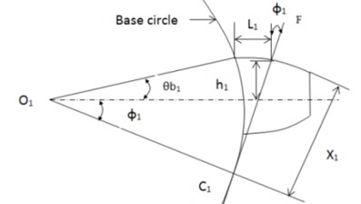
Some of the parameters used in the above equations, viz., , , , and for a spur gear are shown in Fig. 1. , and represent gear width, modulus of elasticity and Poisson’s ratio respectively.
Combining these effects, the stiffness for pinion (1) and gear (2) are determined from the following equation:
Stiffness for Hertzian contact deformation is obtained from the following equation:
Equivalent or total stiffness of the pair of gears can be obtained as follows:
Fig. 1Geometry of a spur gear tooth modeled as a cantilever beam
Batch files are created in MATLAB for stiffness formulations as provided in the above equations. These batch files are used for the FEM procedures from 2D modeling to post-processing in ANSYS. Finally, a file including the deflection values of the nodes was produced; the nodal deflections could also be gained from the software interface. This process was repeated for each gear pair. Then to insert the crack in gears, meshed model file is transferred to FRANC3D software. ANSYS 19 has been used in this study for its compatibility with FRANC 3D. Elliptical cracks are generated in gear teeth using the flaw insertion commands and input data of semi major and semi minor axes of the concerned ellipse. Propagation of crack to rim and crack to tooth are affected with the help of flaw rotation angles.
3. Results and discussion
Mesh stiffness formulation as discussed in the above section has been applied to a pair of spur gears. The geometrical details of the gear pair are provided in Table 1. As stated in earlier section, mesh stiffness has been calculated for a cracked tooth in the gear pair. The crack has been assumed to propagate in elliptical path which has been assumed to move towards both tooth and rim.
Table 1Geometrical details of Involute spur gear pair
Parameter | Driving pinion | Driven gear |
Module (mm) | 5 | 5 |
Number of teeth | 27 | 27 |
Pressure angle (°) | 20 | 20 |
Addendum coefficient (ha*) | 1 | 1 |
Width (mm) | 15 | 15 |
Headspace coefficient () | 0.3 | 0.3 |
Young’s modulus | 200 GPa | 200 GPa |
Gears have been modelled for Finite Element analysis using ANSYS 19 software and the total number of elements and nodes used in the generated mesh are 17264 and 28592 respectively. Three different elliptical paths have been induced separately with the use of flaw insertion in FRANC 3D after importing the meshed gear from ANSYS. Static Structural analysis has been performed using Mechanical APDL launcher having update interval of 2.5 seconds. The paths have been varied considering different values of semi major and semi minor axes of the ellipses, which are enlisted in Table 2.
Table 2Details of elliptical crack progression path
Path of crack progression | Semi major axis (mm) | Semi minor axis (mm) |
Ellipse 1 | 15 | 10 |
Ellipse 2 | 20 | 15 |
Ellipse 3 | 22 | 18 |
All these elliptical paths have been assumed to initiate from the same point at the root of the tooth. Three different crack lengths of 1 mm, 2 mm and 3 mm respectively have been considered for a single set of elliptical crack path with one going towards tooth and the other going towards rim.
The values of gear mesh stiffness calculated for the above cases have been plotted against pinion tooth rotation. Gear rotation that is sufficient to cover the total period of engagement of cracked gear tooth, has been considered for the present study. The plots thus obtained are shown in Fig. 2.
Fig. 2Plots of gear mesh stiffness vs. pinion rotation for crack length of: a) 1 mm, b) 2 mm, c) 3 mm
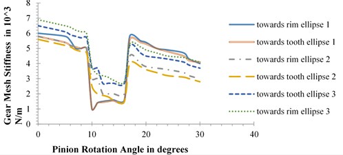
a)
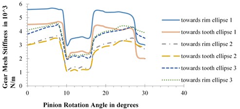
b)
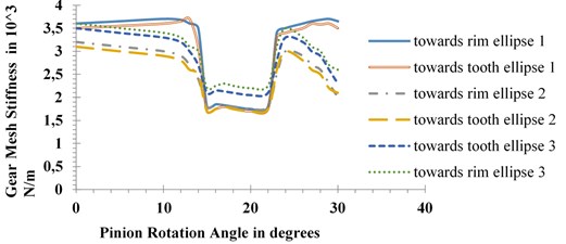
c)
The plots reestablish the fact that with increase in crack length, there is reduction in the values of gear mesh stiffness. The plots also show significant variation in the values of mesh stiffness for different paths of crack progression. However, the effect of path variation is quite different for the three cases. Mesh stiffness values are found to be quite close to each other when the same ellipse moves towards tooth and rim except for the case of ellipse 1 with 2 mm defect. Changes in mesh stiffness values for different paths, i.e., for ellipses 1, 2 and 3 are also most significant in case of 2 mm crack length as shown in Fig. 2(b). For 1 mm defect, highest values of mesh stiffness appear for ellipse 3 followed by ellipse 1 and ellipse 2. For 2 mm 3 mm crack lengths, mesh stiffness value changes in decreasing order of ellipse 1, ellipse 3 and ellipse 2.
4. Conclusions
The effect of crack propagation path on the mesh stiffness of a spur gear pair has been investigated in the current study. The cracks have been assumed to propagate along different elliptical paths defined by their semi major and semi minor axes. Crack lengths of 1 mm, 2 mm and 3 mm have been considered on all the paths for a comparative analysis. Finite element analysis has been carried out using ANSYS 19 software in association with FRANC 3D. Static structural analysis was also performed using Mechanical APDL. The numerical results obtained from this study show that there is significant variation in values of gear mesh stiffness for different paths of progression, the variation being maximum for 2 mm crack length. No significant variation has been observed between mesh stiffness values for crack propagation towards tooth and rim.
References
-
Cornell R. W. Compliance and stress sensitivity of spur gear teeth. Journal of Mechanical Design, Vol. 103, Issue 2, 1981, p. 447-459.
-
Yang D. C. H., Lin J. Y. Hertzian damping, tooth friction and bending elasticity in gear impact dynamics. Journal of Mechanisms, Transmissions and Automation in Design, Vol. 109, 1987, p. 189-196.
-
Chaari F., Baccar W., Abbes M., Haddar M. Effect of spalling or tooth breakage on gearmesh stiffness and dynamic response of a one-stage spur gear transmission. European Journal of Mechanics A: Solids, Vol. 27, 2008, p. 691-705.
-
Chaari F., Fakhfakht, Haddar M. Analytical modelling of spur gear tooth crack and influence on gearmesh stiffness. European Journal of Mechanics A: Solids, Vol. 28, 2009, p. 461-468.
-
Parey A., Tandon N. Spur gear dynamic models including defects: a review. Shock and Vibration Digest, Vol. 35, Issue 6, 2003, p. 465-478.
-
Parey A., Badaoui M. E., Guillet F., Tandon N. Dynamic modelling of spur gear pair and application of empirical mode decomposition-based statistical analysis for early detection of localized tooth defect. Journal of Sound and Vibration, Vol. 294, 2006, p. 547-561.
-
Mohammed O. D., Rantatalo M., Aidanpaa J. Dynamic modelling of a one-stage spur gear system and vibration-based tooth crack detection analysis. Mechanical Systems and Signal Processing, Vol. 54, Issue 55, 2015, p. 293-305.
-
Ma H., Zeng H. Review on dynamics of cracked gear systems. Engineering Failure Analysis, Vol. 55, 2015, p. 224-245.
-
Cooley C. G., Liu C., Dai X., Parker R. G. Gear tooth mesh stiffness: a comparison of calculation approaches. Mechanism and Machine Theory, Vol. 105, 2016, p. 540-553.
-
Wu S., Zuo M., Parey A. Simulation of spur gear dynamics and estimation of fault growth. Journal of Sound and Vibration, Vol. 317, 2008, p. 608-624.
-
Zhou X., Shao Y., Lei Y., Zuo M. Time-varying meshing stiffness calculation and vibration analysis for a 16-DOF dynamic model with linear crack growth in a pinion. Journal of Vibration, Acoustics, Vol. 134, Issue 1, 2012, p. 011011.
-
Chen Z., Shao Y. Dynamic simulation of spur gear with tooth root crack propagating along tooth width and crack depth. Engineering Failure Analysis, Vol. 18, Issue 8, 2011, p. 2149-2164.
-
Lewicki D., Ballarini B. Effect of rim thickness on gear crack propagation path. Journal of Mechanical Design, Vol. 119, Issue 1, 1997, p. 88-95.
-
Mohammed O. D., Rantatalo M., Aidanpaa J., Kumar U. Vibration signature analysis for gear fault diagnosis with various crack progression scenarios. Mechanical Systems and Signal Processing, Vol. 41, 2013, p. 176-195.
-
Karma V., Agarwal A. K. Calculation of high contact ratio mesh stiffness and load sharing ratio using MATLAB and excel spreadsheet, International Journal of Advance Research in Science and Engineering, Vol. 5, Issue 9, 2016, p. 104-119.
About this article

