Abstract
Capacitors with high voltage and capacity values are used in most induction coilguns that are designed and constructed. The fact that capacitors are quite bulky and slow in energy transfer and how a coilgun can be made without using capacitors is the study subject of this article. Two and four coil gun samples were made to find the essential components of an electric gun, and the results are reported in this article. The accuracy of the results is also confirmed by FEMM analysis for these models. The harmony of experimental and theoretical results shows that smaller and low cost portable electrical weapons can be a powerful alternative to firearms in the future.
Highlights
- Coilgun design and evaluation without capacitor
- Coilgun without capacitor
- Portable electrical guns
1. Introduction
The most traditional weapons work by the gases expanding with the explosion of gunpowder and forcing a projectile out of the barrel at high speed. The thrust of these systems is provided by the gunpowder that is placed in the closed tube behind the projectile in the barrel. These weapons in the firearms group are extremely noisy, leave gunpowder residue in the barrel, and prevent it for continuous use. Some disadvantages draw attention to electromagnetic weapons [1]. Even though the history of these systems, also called electromagnetic launchers, goes back to the beginning of the previous century, there are still many obvious problems, and therefore dozens of scientific articles are published every year. However, electromagnetic launch systems have significant advantages over existing chemical launch systems. These can be divided into two categories railguns and coilguns. While the railgun is a kind of launch system where the acceleration of a projectile stems from the Lorentz force, the coilgun operates with the reluctance force based on magnetic flux changing [2]. However, both systems have inherent problems and limitations, and the biggest problem is the energy lost when converting electrical energy into kinetic energy [3]. This work is related to coil guns. An inductive-based coil with good launch characteristics is relatively complex. Because the entire launch process is transient, and the mutual inductive interactions between field coils and projectile change over time. Therefore, the design, which also includes numerical approaches, requires a system modeling technique based on artificial intelligence. In its most conventional form, coilguns produce a strong magnetic field to accelerate magnetic projectiles. It uses a high current charged capacitor array as a source to produce this field. The projectile located on one side of the coil is pulled into the center by magnetic induction, and the applied force is proportional to the change in the inductance of the coil. The force exerted on the projectile is always in a direction that increases the inductance of the coil. One way to increase the efficiency of this system is to speed up the projectile by activating several coils sequentially. The multi-coil design is designed to maximize projectile speed, and there is no upper theoretical limit for speed. Even if the projectiles can reach the speed of sound, they are still very quiet and require much less maintenance than they are clean [4]. In a multi-coil system, sequential activation of the coils is carried out depending on the position and instantaneous speed of the projectile. Therefore, the working time of each coil will be different. The critical point in the study is that the circuit elements that will provide these timings can reach this speed. We do not use capacitors, which are the slowest circuit elements and used as batteries in many studies [5, 6]. Instead of capacitors, we will use fast DC power sources that can output arbitrary voltage but give high currents.
The purpose of the coils used in the construction of electrical weapons is to transfer the stored magnetic energy to the projectile as kinetic energy. Capacitors were used in all-electrical weapon models mentioned in the literature review. It was not used in this study. A coil already stores electrical energy by converting it into magnetic energy. We use this energy directly. In our model, only the internal resistance of the coil limits the energy loss. Even if very high currents cause the coils to heat up, the coils do not heat because the magnetic force is proportional to the change rate of the current, not the current. For this reason, the switching times of the currents passing through the coils are very important. Switching speeds of Mosfets used today are more than sufficient in this study, and heat is not generated due to their very small internal resistance. In addition, since the capacitor is not used, smaller and lower cost portable electrical weapons can be made due to the volume gap gained.
2. Methods
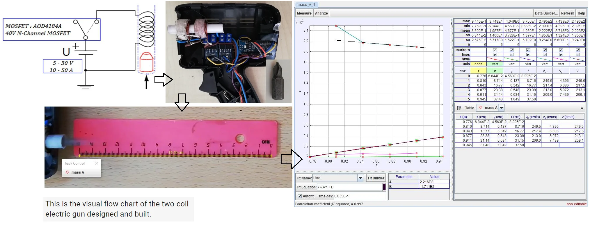
In this study, high speed and low power consumption Mosfets are used to switch the coils that will produce the magnetic field required to accelerate the projectiles. These Mosfets transfer DC power directly to the coils and supply the instantaneous power requirement. Fig. 1 shows the model structure of a coilgun with a single-coil. The switching pulses of the AOD4184A 40 V N-Channel Mosfets used in these models are controlled by an Arduino-nano microcontroller. The physical equivalent of this model and its electrical equivalent is shown in Fig. 2 and 3, respectively. The launch process is one-step. The timing pulse sent by the microcontroller drives the Mosfet, which transmits the battery power directly to the coil. This process causes a very large current to pass through the coil and hence creates a strong magnetic field. This field causes the projectile to be pulled with great acceleration and speeds up into the coil center. To prevent the projectile from being held in the center of the coil, the timing pulse must be switched off before the projectile exceeds half the length of the coil. The width of the timing pulse varies depending on the dimensions of the projectile, but the dependencies of mass and magnetic properties were ignored in this study [5, 6]. One note, an induction coilgun should not be confused with a reluctance-based coilgun [7].
Fig. 1Model structure of a coilgun with a single coil [Original]
![Model structure of a coilgun with a single coil [Original]](https://static-01.extrica.com/articles/21627/21627-img1.jpg)
The coils of a reluctance coilgun not only provide the magnetic field that accelerates the projectile, produces the magnetic field inside the projectile. In an induction coilgun, the projectile carries a current and produces its own magnetic field.
Fig. 2Physical equivalent of a single coil gun [6]
![Physical equivalent of a single coil gun [6]](https://static-01.extrica.com/articles/21627/21627-img2.jpg)
Fig. 3Electrical equivalent of a single coil gun [Original]
![Electrical equivalent of a single coil gun [Original]](https://static-01.extrica.com/articles/21627/21627-img3.jpg)
2.1. Theory and implementation
We will use the basic equations of classical mechanics in a different way and get theoretical values from experimental results. We assume that all the magnetic energy stored in the coil is converted into kinetic energy:
In this equation, the velocity and mass of the projectile are and , respectively, the inductance of the coil , the current passing through the coil is . The product of is the power consumed in the coil. Fig. 4 shows the empty shot voltage change made in the single-coil model. The positive and negative peaks shown in the graphic on the left are found by using Lenz’s law and are the result of a quick switching of Mosfets. The enlarged version of the positive peak is on the right graph. Using this chart, we can calculate the inductance of the coil. Normally, it is necessary to perform the ac analysis of the circuit given in Fig. 3, which can be found in any general physics book; we will only use the result here:
where, is the time consumed to increase the voltage applied to the coil by 0.632 when the Mosfet is triggered. This time is equal to the time constant of the circuit. The value of was measured as 43.5 µH from the graph and was calculated as 22.0 µH. The internal resistance of the coil is 168 mΩ. Measurements were made with Picoscope 3406B USB oscilloscope, Keithley, and Fluke multimeter devices.
Fig. 4Empty shot voltage variation in the single coil model [Original]
![Empty shot voltage variation in the single coil model [Original]](https://static-01.extrica.com/articles/21627/21627-img4.jpg)
Fig. 5 shows the projectile shot voltage change in the single-coil model. The graphic on the left shows a sharp rise in the positive peak, and there is a loss of symmetry in the negative peak. The reason for the corruption in the negative peak may be due to the projectile length being longer than the coil length because the inductance of the coil changes with the motion of the projectile. The lengths of the coil and projectile are 14 mm, 25 mm, respectively. The enlarged version of the positive peak is on the right graph.
Fig. 5Projectile shot voltage variation in single coil model [Original]
![Projectile shot voltage variation in single coil model [Original]](https://static-01.extrica.com/articles/21627/21627-img5.jpg)
The inductance of the coil could not be calculated using this chart. While the projectile was stationary in the middle of the coil, its inductance was measured 21.3 µH. In Figs. 4 and 5, the voltage values of the plateau between the two peaks are almost the same, and the duration can be shortened and extended as required by the software. This is independent of the supply voltage. This feature is not available for coil guns with charge-and-discharge capacitors. The output velocity of the projectile can be calculated from Eq. (1). When the maximum inductance of the coil is 22.0 µH and the maximum current passing through the coil is 14.83 A, this speed is 106.8 cm/s (12 V variable power supply can be increased up to 40 V). The kinetic energy of the projectile changes with the position [8]:
3. Materials and equipment
3.1. The ejection coil
Two different prototype gun models with two and four coils were made by using the semi-experimental single-coil gun model, as shown in Figs. 6 and 7. In Fig. 6, the tube passing through the center of the coils has no magnetic property and is an insulator. The paper tube was then hardened. The diameter of the tube should be slightly larger than the diameter of the projectile to be used. The number of coils to be wound on the tube will affect the launch speed. In the thumbnail in Fig. 7, there are four coils wrapped on the tube. Winding number, thickness, and length of the coils are the parameters affecting the launch speed. The most important thing is timing pulses that take into account the distance between the coils [6, 9]. In this study, the turn number of coils is 85, the length 14 mm, the thickness 6.55 mm, and the wire diameter 1 mm2. These are average values and are not critical.
3.2. Arduino and power Mosfets
A microcontroller was used to control the current passing through the coils that created the magnetic force to accelerate the projectile. A commercial product, Arduino Nano, is a development board that uses an ATmega328P microcontroller [10]. It was used in this study because of its 12 MHz clock speed and small size. The timing pulses of the Mosfets, which limit the current passing through the coils, are produced by this microcontroller. Switching times of Mosfets should be around nanoseconds. Fig. 8 displays the circuit diagram of the four-coil gun. If the diodes D1 ... D4 shown in the scheme are not used, the outputs of the Mosfets can be burned.
Fig. 6Two-coil gun and test projectile (ratchet screwdriver, the thumbnail) [Original]
![Two-coil gun and test projectile (ratchet screwdriver, the thumbnail) [Original]](https://static-01.extrica.com/articles/21627/21627-img6.jpg)
Fig. 7Four-coil gun with coils (the thumbnail, back side) [Original]
![Four-coil gun with coils (the thumbnail, back side) [Original]](https://static-01.extrica.com/articles/21627/21627-img7.jpg)
3.3. Velocity measurements
Fig. 9 shows the moment of the projectile exiting from the barrel after firing in the two-coil gun. Various methods are available to measure this speed. The parabolic method using the time-independent orbital equation, the light-sensitive fence gate method that measures flight time, and the ballistic pendulum method using momentum conservation is the most commonly used speed measurement method [11]. Free video analysis and modeling tool Tracker program based on open source physics (OSP) Java framework was used to measure this speed. It is designed for use in physics education and can combine captured videos with computer modeling [12]. A mobile phone’s camera (1080p @ 30fps) was used to find the speed of the projectile. The videos taken were transferred to the computer where the Tracker program was installed, and the speed of the projectile was measured using the recommended instructions for speed measurements. Fig. 10 displays the results of the data analysis produced by the Tracker program. The data are given in the cgs unit system. The position and speed equation of the projectile was found with the “auto-fit” option:
In the last equation, we excluded the initial velocity of the projectile on the grounds that it was not linear. There is a break here by gravity, and its value is –972.727 cm/s2. The result is that the slope of the velocity equation is expected to be negative; the projectile hitting the ground continues on its path horizontally.
Fig. 8Four-coil gun circuit schema [Original]
![Four-coil gun circuit schema [Original]](https://static-01.extrica.com/articles/21627/21627-img8.jpg)
Fig. 9The moment the projectile leaves the barrel, black shade [Original]
![The moment the projectile leaves the barrel, black shade [Original]](https://static-01.extrica.com/articles/21627/21627-img9.jpg)
Fig. 10Data analysis results [Original]
![Data analysis results [Original]](https://static-01.extrica.com/articles/21627/21627-img10.jpg)
3.4. FEMM analysis
FEMM is an analysis program written in Lua language. Lua uses a measurement taken in a simulation step as a parameter in the next step. It is easy to examine the pulling force created by the current passing through a coil by FEMM analysis [13, 14]. After creating a physical model of the work to be done, the program tries to reach the solution by numerically integrating the dynamic equations of the projectile [8, 9]. The FEMM analysis results of the physical model for a single-coil are shown in Fig. 11. According to the results, the inductance of the coil is 52.71 µH, and its internal resistance is 84 mΩ. Fig. 12 is the magnetic force change that acts when the projectile is drawn by the coil. In the middle of the coil, the force is maximum, and at this point, the Mosfet must interrupt the current otherwise, the projectile will be locked. The codes required to simulate the change of force on the projectile were written in Python language. In order to work Python language with the FEMM analysis package, pyfemm 0.1.1 module must be imported. For linear problems, the magnetic field co-energy is numerically the same as the magnetic energy in a coil, and its simulated value is 0.0024331 J. We calculated the speed of the projectile from this result. This value should be compatible with the value given by the Tracker program. If we take the derivative of the position with respect to time, we find the speed of the projectile. The kinetic energy of the projectile can be calculated from this speed value:
We divided the kinetic energy into four because the two-coil gun has four semi-coils due to symmetry. The magnetic force is directly proportional to the field lines passing through the projectile, and in simulation, the left half of the projectile is outside due to symmetry. If we multiply the magnetic field energy value given by the simulation by four, we will find the speed value given by the Tracker program.
Fig. 11FEMM analysis results [Original]
![FEMM analysis results [Original]](https://static-01.extrica.com/articles/21627/21627-img11.jpg)
Fig. 12Force change on the projectile [Original]
![Force change on the projectile [Original]](https://static-01.extrica.com/articles/21627/21627-img12.jpg)
4. Conclusions
In this study, the highest velocity value we obtained in firing tests with a four-coil gun was measured as 17.1 m/s and is unstable. The projectile is often locked in the barrel. The reason for this is obvious. The projectile has variable speed as it passes through the coils, and this may not be linear because of shaking hands, running out of battery. Due to such situations, it is inevitable that Mosfets are triggered with different time periods. Sensors are needed to measure the velocity of the projectile passing through the coils. With the help of these sensors, the position and speed of the projectile should be calculated that exact moment and the Mosfets should be opened and closed. The purpose of this article is to prove that large capacitors are not required to make coil guns. Mosfets, which can switch quickly in the nanoseconds range, can keep the coils under constant voltage and can supply huge current to the coils. We can make a simple calculation. If the speed of the projectile thrown from the coil with a current of 14.83 A (2.5 V) is 2.216 m /s, similarly, this speed is expected to be 11 m/s at 12 V. You can manually test it, probably the projectile will lock in the middle of the coil, and the coil will heat up. A little surprise, the coilgun is launching a double projectile. Portable electrical guns will silently replace firearms in the future.
References
-
Williams Karl P. Electromagnetıc coil gun project. Nuts and Volts Magazine, 2008, https://www.nutsvolts.com/magazine/article/electromagnetic_coil_launcher_project.
-
Klimas M., Grabowski D., Piaskowy A. Efficiency analysis of an electromagnetıc launcher. Elektryka, Zeszyt, Vol. 62, Issue 2(238), 2016.
-
Kim S. W., Jung H. K., Hahn S. Y. An optimal design of capacitor-driven Coilgun. IEEE Transactions on Magnetics, Vol. 30, Issue 2, 1994, p. 207-211.
-
Lee S. J., Kim, J. H., Kim S. H. Design and experiments of multi-stage coil gun System. Journal of Vibroengineering, Vol. 18, Issue 4, 2016, p. 2053-2060.
-
Skala B., Kindl V. Electromagnetic Coil Gun – Construction and Basic Simulation. Mechatronics, 2013, p. 87-93.
-
Paul J. Coilgun Systems ©2001-2006, http://www.coilgun.eclipse.co.uk/theory.html.
-
McAfee S. R. Electromagnetic Coil Gun. Final Report, Rutgers School of Engineering, 2013.
-
Hawley J. Physics of an axial coil gun, http://jimhawley.ca/downloads/Axial_Coil_Gun/An_Axial_Coil_Gun_Part_I.pdf.
-
Hansen B. Practical Coilgun Design, https://www.coilgun.info/theory/home.htm.
-
Arduino Nano, https://store.arduino.cc/usa/arduino-nano.
-
Paul J. Measuring Speed, http://www.coilgun.eclipse.co.uk/projectile_speed_measurement.html.
-
Tracker. Video Analysis and Modeling Tool, https://physlets.org/tracker/.
-
Baltzis K. B. The finite element method magnetics (FEMM) freeware package. Education and Information Technologies, Vol. 15, 2010, p. 19-36.
-
Meeker D. Lua Scripting Example: Coil Gun. 2004, http://www.femm.info/wiki/CoilGun.
Cited by
About this article

