Abstract
The behavior of the electromagnetic (EM) launcher depends on the structure of the construction. The dynamics of the EM construction and the local effects of the EM forces are topical issue in exploring and designing EM launcher device. This paper is aimed to refine mechanical behavior of the open barrel design EM launcher structure due to EM force evaluated by EM analysis based on three different shapes of armatures. The 3D finite element EM model was generated and the J×B force density distribution in the rail volume was calculated. The results of EM model calculations were applied further as input for structural mechanics model. The results of the finite element EM and mechanical analysis of the armatures influence are presented.
1. Introduction
The linear Electromagnetic (EM) launcher is the mechatronic accelerating device aimed at accelerating small mass bodies or other devices such as nan satellite. The idea of linear EM launcher was put forward in the 19th century. The first efforts to develop an EM launcher were undertaken by Kristian Birkeland in Norway. Over the last 100 years, many experiments have been made in order to improve the launcher design and to create more powerful devices. The earlier researches on the subject are reviewed in [1]. A scenario for a future developments in Europe [2] presumes the potential possibility to reach muzzle velocities higher than 2.5 km/s.
EM accelerators cover a wide range of applications. This article deals with an accelerator type, known in the literature as railgun. The mechanical structure of the device presents two electric current-conducting rails and an armature between them [3, 4]. The power supply equipment (e.g. a capacitor and a pulse forming unit) and other components (e.g. switches) are required in order to operate an EM launcher. The strong electrical currents used on conducting materials result the strong Lorentz forces. In particular the projectile is accelerated by the Lorentz force acting on the armatures. Advances in EM launch science and technology can be found in [5, 6].
Despite of common physical principles, different structural concepts have been implemented to withstand repelling forces. The experimental research facility of RApid FIre RAilgun (RAFIRA) designed and explored in French-German Institute of Saint Louis (ISL) [7, 8]. The facility presents open barrel design housing consisting of two bars of length 3000 mm connected by a set of bolts in order to resist the rails repelling force. The model can operate in multi-shot mode (up to three shots in a row). The view of the EM launcher is shown in the Fig. 1(a).
Operational setup (Fig. 1(b)) illustrates that the accelerating motion of armature is of complex multi-physical nature. Investigation of EM is performed by combining different techniques and increasing role of numerical simulations gives an opportunity to detect data which are difficult to obtain experimentally. Usually, mechanical calculations are considered in simplified manner independently on electromagnetic properties [9, 10]. The uniform magnetic pressures acting on the rail surfaces (high-frequency approximation) and repelling the rails from each other’s were evaluated on experimental results. Recent developments in the field of computational physics allow apply complex multi-physical (electromagnetic-mechanical) analysis [11].
This paper is aimed to refine mechanical behavior of the armature-rail interaction in linear EM launchers due to volume distribution of EM force.
Fig. 1The picture of EM launcher RAFIRA: a) the view of experimental facility, [9], b) illustration of EM launcher operation principle
![The picture of EM launcher RAFIRA: a) the view of experimental facility, [9], b) illustration of EM launcher operation principle](https://static-01.extrica.com/articles/19832/19832-img1.jpg)
a)
![The picture of EM launcher RAFIRA: a) the view of experimental facility, [9], b) illustration of EM launcher operation principle](https://static-01.extrica.com/articles/19832/19832-img2.jpg)
b)
2. Governing equations and computational method
Multi-physical nature and complex 3D geometry of the railgun complicate numerical simulation. Different simplified engineering and quite complex continuum models recently applied for simulation purposes are reviewed in [12]. Considering railgun as continuum, EM behavior could be described using Maxwell equations. Generally, EM analysis of railgun is limited to evaluation of magnetic field . Consequently, the straight-forward finite element method (FEM) formulation limiting to a magnetic vector potential may be used [13]:
Therefore, in order to present the vector potential solution, the definition of magnetic vector potential can be used:
It can be shown that obeys the following equation [14]:
where is the volume of space filled with charges, the quantities of , are the distance from zero point till current caring point and from zero point till calculating point, is the current density at certain point and is the magnetic permeability. The integration is performed in the entire space including conductors and nonconductive regions.
The EM force density applied on the rails is determined as Lorentz’s force The resultant magnetic force acting in the specified volume is calculated by integrating the EM force density over volume of conducting parts:
The integrated magnetic force is used further for solving the mechanical models as external load.
Mechanical characterization of structure displacements and stress during launching is established using the EM forces Eq. (3). The basic equation of motion solved by a finite-element transient dynamic structural analysis is:
where is mass matrix, is damping matrix, is stiffness matrix, is nodal acceleration vector, is nodal velocity vector, is nodal displacement vector, and is the load force.
The developments of the FEM as well as the numerical analysis of the EM and mechanical models according to Eqs. (1-4) were done using FEM software COMSOL.
3. Results and discussion
Two different, EM and structural, 3D FE models of the RAFIRA railgun (Fig. 1(a)) were developed.
For 3D EM modeling various simplifications were introduced. The model geometry is described in Cartesians coordinates, where axis points longitudinal direction, i.e. direction of projectile motion, while axis points direction of the rails repelling force. Regarding the symmetry of the barrel, the structure is symmetric with respect to - and - planes, and only the positive quadrant is considered. Thus, the EM model includes the half of a rail and housing bar and one quarter of armature [15]. The computational domain is not restricted to the structural part, but also involves the ambient air which is necessary for magnetic field calculations.
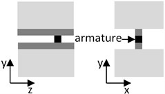
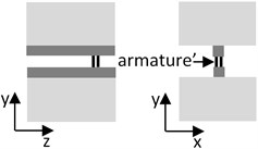
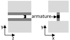
Three different types of armature were investigated by considering rail-armature interaction. The models setup are illustrated in Table 1. The cuboid armature presents single cuboid having size of rail width, while the distributed armature consists of four copper cylinders.
Table 1Schematic setup of armature models used in the EM analyses
Cuboid armature model | Distributed armature model | C-shape armature model |
 |  |  |
For EM simulations the numerical model was used which is verified in [16]. In previous model the rail-armature model with copper cuboid armature was investigated. Essential results of EM simulation are illustrated in Fig. 2, where 2D distributions of the y-component of EM force density in the form of colored contour plots were presented. The results obtained for distributed armature clearly show the local armature shape dependent distributions of the force density. Uniform distribution on the sliding surface (Fig. 2(a)) illustrates dominance of the skin effect occurring outside the contact. Two different variations in vertical longitudinal sections, central section A (Fig. 2(b)) and section B (Fig. 2(c)) illustrate inhomogeneity of cross-sectional loading. This undesirable effect indicates available imperfection of the sliding surface, which may lead to instability of projectile motion. In the case of C-shape armature (Fig. 2(d)), the different local force density distribution was observed.
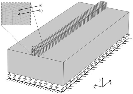
A 3D structural FE model of the RAFIRA railgun shown in Fig. 3 was prepared. Considering the symmetry, it comprises only one half of the rail section and one half of the supporting bar. The steel bolts playing the role of discrete supports were replaced by an elastic foundation layer continuously supporting the bar (Fig. 3). The volume of the structure is covered by the orthogonal grid used for generation of the finite element mesh, where rectangular parallelepipeds are applied for the volume EM force load discretization. The discrete EM forces received from EM analysis calculations. The volume of the rail is divided into (5×4×10) mm sized cells (Fig. 3(b))), but smaller (5×2×10) mm cells were used for description of skin effect near the sliding surface (Fig. 3(a)).
Fig. 2Simulation results – Contour color plots of y-component of magnetic force density in the case of the distributed armature a)-c) and: C-shape armature d). Distribution on sliding surface a) and in longitudinal sections A b) and B c)
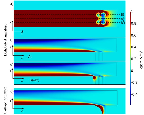
Fig. 3The 3-D structural model used for mechanical analysis calculation
The results of the EM calculations were used as load for mechanical calculations using the model described in Fig. 3. The obtained EM forces were recalculated according to Eq. (3) and inserted into mechanical model Eq. (4).
Among various mechanical criteria, the gap between the rails is significant parameter governing the efficiency of energy transition from capacitor to projectile. Even small imperfection of the rail surface in range of several dozens of microns change the gap and may contribute the motion of the projectile.
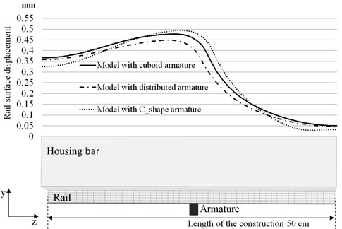
Three different selections of the forces obtained during the rail-armature interactions for the armature shapes listed in table 1 were applied for evaluation of the rail displacements. Simulation results in terms of displacement profiles of the central section of the rail surface are plotted in Fig. 4.
As was expected, an influence of the armature can be stated for three cases. The amplitude changes in comparison to the three armatures cases are about 0.05 mm. The highest contribution to deformation of the rail surface is due to influence of C-shape armature, because the rail surface displacement is influenced not only from EM force in the rail but also from the C-shape armature [17]. The lowest impact to the rail form armature was obtained with distributed armature. This can be due to distributed Lorentz force distribution in the armature region. The current flow does not have high concentration at each point. The effect of armature propulsion was not taken into account. The point out that at the shape of the armature one should try to be as precise as possible because it is exactly there where the sliding electrical contact may be influenced by rail displacements.
Fig. 4Profiles of the surface displacements in the central section of the rail occurring when armature is in the middle
4. Conclusions
The contribution of EM rail-armature interaction is demonstrated, and some conclusions are formulated as follows. The numerical results obtained by electromagnetic FE analysis describe the distribution of magnetic field and EM force volume density over the rails volume of an EM launcher. The smooth transitional character of the longitudinal variation of the dominant repelling force component is shown, where increased contribution in the vicinity of the armature, but reduced effect in the longer distance is estimated. As a result of EM analysis, corrected profile of the rail displacement and more realistic variation of inter-rail gap is obtained. Additionally, the observed non-uniform transversal variation of the EM force component in the rail section indicates effect of the transversal bending, which could have influence of construction stability during launching process. The local effect also demonstrates the small difference between different types of armatures. The lowest impact to mechanical deformation of rail surface is shown by using of the distributed armature.
References
-
Mcnab I. R. Early electric gun research. IEEE Transactions on Magnetics, Vol. 35, Issue 1, 1999, p. 250-261.
-
Hundertmark S., Lancelle D. A scenario for a future European shipboard railgun. IEEE Transactions on Plasma Sciences, Vol. 43, Issue 5, 2015, p. 1194-1197.
-
Marshall Richard A., Wang Y. Railguns: Their Science and Technology. China Machine Press, 2004.
-
Keshtkar A., Bayati S., Keshtkar A. Effect of rail’s material on railgun inductance gradient and losses. 14th Symposium on Electromagnetic Launch Technology, 2008.
-
Engel T. G., Timpson E. J. A general theory of DC electromagnetic launchers. Journal of Applied Physics, Vol. 118, Issue 8, 2015, p. 83902.
-
Shellock M. R. Multiphysics modeling of a rail gun launcher. The International Journal of Multiphysics, Vol. 2, Issue 4, 2009, p. 421-436.
-
Schneider M., Woetzel M., Wenning W., Walch D. The ISL rapid fire railgun project RAFIRA part I: Technical aspects and design considerations. IEEE Transactions on Magnetics, Vol. 45, Issue 1, 2009, p. 442-447.
-
Schneider M., Woetzel M., Wenning W. The ISL rapid fire railgun project RAFIRA – part II: first results. IEEE Transactions on Magnetics, Vol. 45, Issue 1, 2009, p. 448-452.
-
Schuppler C., Alouahabi F., Schneider M. Electromechanical aspects of reliable loading procedures for multishot railguns. IEEE Transactions on Plasma Sciences, Vol. 41, Issue 5, 2013, p. 1387-1391.
-
Tumonis L., Schneider M., Kačianauskas R., Vadluga V. The structural mechanics of rail guns with discrete supports showing the influence of DES. IEEE Transactions on Plasma Sciences, Vol. 39, Issue 1, 2011, p. 144-148.
-
Stonkus R., Račkauskas J., Schneider M., Kacianauskas R. Structural mechanics of railguns with open barrels and elastic supports: the influence of multishot operation. IEEE Transactions on Plasma Sciences, Vol. 43, Issue 5, 2015, p. 1510-1515.
-
Yang F., Zhao Z., Liu Y., Wu Y., Chen Z., Sun H., Rong M. Electromagnetic-mechanical characteristics study of a high-speed electromagnetic launcher. IEEE Transactions on Plasma Sciences, Vol. 44, Issue 10, 2016, p. 2218-2225.
-
Bíró O., Koczka G., Preis K. Finite element solution of nonlinear eddy current problems with periodic excitation and its industrial applications. Applied Numerical Mathematics, Vol. 79, 2014, p. 3-17.
-
Beno J. H. Three-dimensional rail-current distribution near the armalztre of simple, square-bore, two-rail railguns. IEEE Transactions on Magnetics, Vol. 27, Issue 1, 1991, p. 106-111.
-
Musolino A. Electromagnetic analysis in devices with sliding contacts. International Journal for Computation and Mathematics in Electrical and Electronic Engineering, Vol. 20, Issue 2, 2001, p. 463-472.
-
Schneider M., Račkauskas J., Löffler M. J. Electromechanical modeling of components of a linear electromagnetic accelerator. IEEE Transactions on Plasma Sciences, Vol. 41, Issue 10, 2013, p. 2796-2799.
-
Johnson A. J., Moon F. C. Elastic waves in electromagnetic launchers. IEEE Transactions on Magnetics, Vol. 43, Issue 1, 2007, p. 141-144.
About this article

