Abstract
There is a design of vibrating machine proposed in this paper. In this vibrating machine low-frequency vibrations are used to form cavitation cavities in a liquid substance in order to disinfect it. To study the dynamics of a vibrating machine, an analytical model has been created, which makes it possible to determine the change in the maximum pressure in the working body of a vibrating machine and analyze the influence of drive operating modes and design parameters on the efficiency of the water disinfection process. From the accomplished experimental studies, graphical dependences of the influence of design parameters and drive operating modes on the change in maximum pressure in the working body of a vibrating machine are obtained. Using video, we visualized the processes taking place in the working body of the vibrating machine, and analyzed the occurrence of cavitation phenomena in the working body of the vibrating machine. According to the results of the studies, it is recommended for practical use in vibration machines the frequency boundaries of the drive’s vibrations, the oscillation amplitude, the size of the piston and the holes in it, and their ratio.
Highlights
- This study confirms the efficiency of the proposed construction of a vibrating machine for disinfection of the aquatic environment.
- To obtain a cavitation field in a working medium in a vibration machine with a maximum impulse pressure, it is necessary to withstand a certain combination of design parameters and operating modes of the vibration drive unit.
- Experimental studies have confirmed the adequacy of the proposed analytical model for determining the maximum impulse pressure versus frequency.
1. Introduction
Cavitation processes are used in various industries to intensify mass transfer and hydromechanical processes. For today, cavitation technology is relevant for the chemical, food, utilities and engineering industries. Usually, the cavitation effect is used as one of the stages of disinfection and wastewater treatment [1-3].
The active industrial use of cavitation processes with the use of different types of installations, machines, aggregates convincingly confirms the high efficiency of this physical phenomenon as an effective means of disinfection, acceleration of chemical reactions, a mechanism for modifying the structure and properties of processed aqueous solutions. The methods of acoustic cavitation are widely used: ultrasonic (US) and hydrodynamic cavitation [4-6]. The development of cavitation technologies using the method of ultrasonic cleaning of water systems is confirmed by the success of sonochemistry and, in particular, by the accumulation of results on the effect of ultrasound on organic [7] and biological objects [2, 8].
By ultrasonically treating household wastewater contaminated with organic substances, it has been experimentally established that cavitation can reduce the value of chemical oxygen consumption by 25-30 % in less than 60 minutes. In addition, it was determined that insoluble compounds turn into soluble [9].
Cavitation is the phenomenon of rupture of a liquid under the action of stresses that occur when a vacuum appears in a drop of liquid. During rupture of a liquid drop, cavities are formed - cavitation bubbles filled with steam or gas. So, the rupture of the liquid is due to a change in the characteristics of velocities and pressures. Cavitation bubbles form in places where the pressure in the liquid becomes lower than a certain critical value. The critical value of the pressure at which the liquid ruptures depends on many factors: the purity of the liquid, its air content, and the state of the surface on which cavitation occurs. Cavitation can occur in a fluid flow having a variable pressure, as well as near and on the surface of bodies of various shapes in places of greatest rarefaction. An alternating pressure field is created in various ways: as a result of a change in the flow velocity (body motion), the influence of the body shape, as a result of vibrational effects on the fluid (ultrasound or vibrational vibrations).
The use of hydrocavitation for the disinfection process and the results of microbiological measurements for water disinfection obtained by the authors are given in [10, 11].
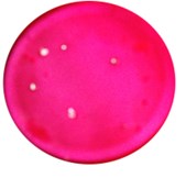
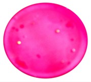
Processing of samples at the installation was carried out for 10, 20, 30 minutes, after which the samples were delivered to the laboratory of Khmelnitsky water utility, where in accordance with GOST 18963-73 (Methods of sanitary-bacteriological analysis) analyzes were performed. The results are presented in Fig. 1.
Fig. 1Photographs of growth samples of microbial colonies: a) control sample without hydrocavitation treatment; b) after treatment for 10 minutes; c) after processing 20 min; d) after treatment for 30 minutes; oscillation amplitude A= 0.002 m; the oscillation frequency of the piston f= 22 Hz; the ratio of the ratio of the area of the hole to the area of the piston Sh/Sp= 0,06

a)

b)
c)
d)
After 30 minutes of treatment by cavitation of water, 3 colonies grew on the nutrient medium of the sample, and 63 colonies of bacteria grew on the control untreated sample. The disinfecting effect of cavitation is based on the effects that occur in turbulent fluid flows. So, during hydrodynamic fluid vibrations, cavitation bubbles appear and disappear. This stimulates phase transitions and increases local temperature and pressure. In addition, at the moments of the formation and disappearance of cavitation bubbles, conditions for the appearance of electric charges and magnetic fields are created in gas-filled cavities. Thus, the liquid processed by cavitation is exposed to thermobaric and electromagnetic effects. A feature of the cavitation method of water treatment is that a high degree of water disinfection from eggs and larvae of parasites is achieved due to their mechanical destruction by shock waves. For the destruction of bacteria and viruses, the thermobaric effect is enhanced by a local electrostatic effect, when the induced electric potentials are breaking through their membranes and shells.
At the stage of the direct action of acoustic vibrations, only chemically active gases, О2 and Н2, can influence the process flow. Ultimately, the effect of cavitation on aqueous solutions is reduced to a single process - the splitting of water molecules in cavitation bubbles. Regardless of the nature of the substances dissolved in water, acoustic vibrations affect only water, which leads to a change in its physicochemical properties - an increase in pH, electrical conductivity, the number of free ions and active radicals, as well as the structuring and activation of molecules. In addition, the reaction rate increases sharply, excited by vibrations of water molecules with hydrogen radicals with the release of OH and H2 components. These processes saturate the liquid with radicals ОН-, О-, О+ and O2, H2 active gases. On the other hand, electrical unsteady forces of interaction between neighboring dipoles grow which increase their vibrations as an integral object and increase the likelihood of destruction of the liquid crystal structure of water. To increase the efficiency of the process, it is necessary to increase the multiplicity of these effects, causes a high degree of return of the restructuring and leads to a partial return of water to the state of the previous structure and, as a result, to a low degree of its final restructuring.
Over the past period, a new direction has appeared in the creation of vibrating equipment for treating water with cavitation, which ensures that water is given new properties and its disinfection [12]. However, there are some drawbacks inherent to these installations – a short time of a single stay of the liquid in the state of occurrence of the cavitation zone.
Several vibration machines of the piston type with an eccentric drive have been created for cavitation treatment of water, in order to disinfect and change its properties [13, 14], in which the water is subjected to multiple reciprocating passages (cyclic hydrocavitation) through the hole in the piston. The use of such a drive unit makes it possible to carry out a rigidly controlled influence on the process of the appearance of cavitation cavities with the formation of cavitation bubbles by selecting the design parameters of the machine and operating modes of its drive unit.
2. The relevance of research
The study of the disinfection of water streams remains a significant scientific and technical task and a public problem. Therefore, the study of the dynamics of the disinfection process using cavitation during fluid vibrations, the creation of new designs of vibration machines, in which the fluid acts as an object that is subjected to controlled vibration action, is an urgent task.
3. Presentment of the main material
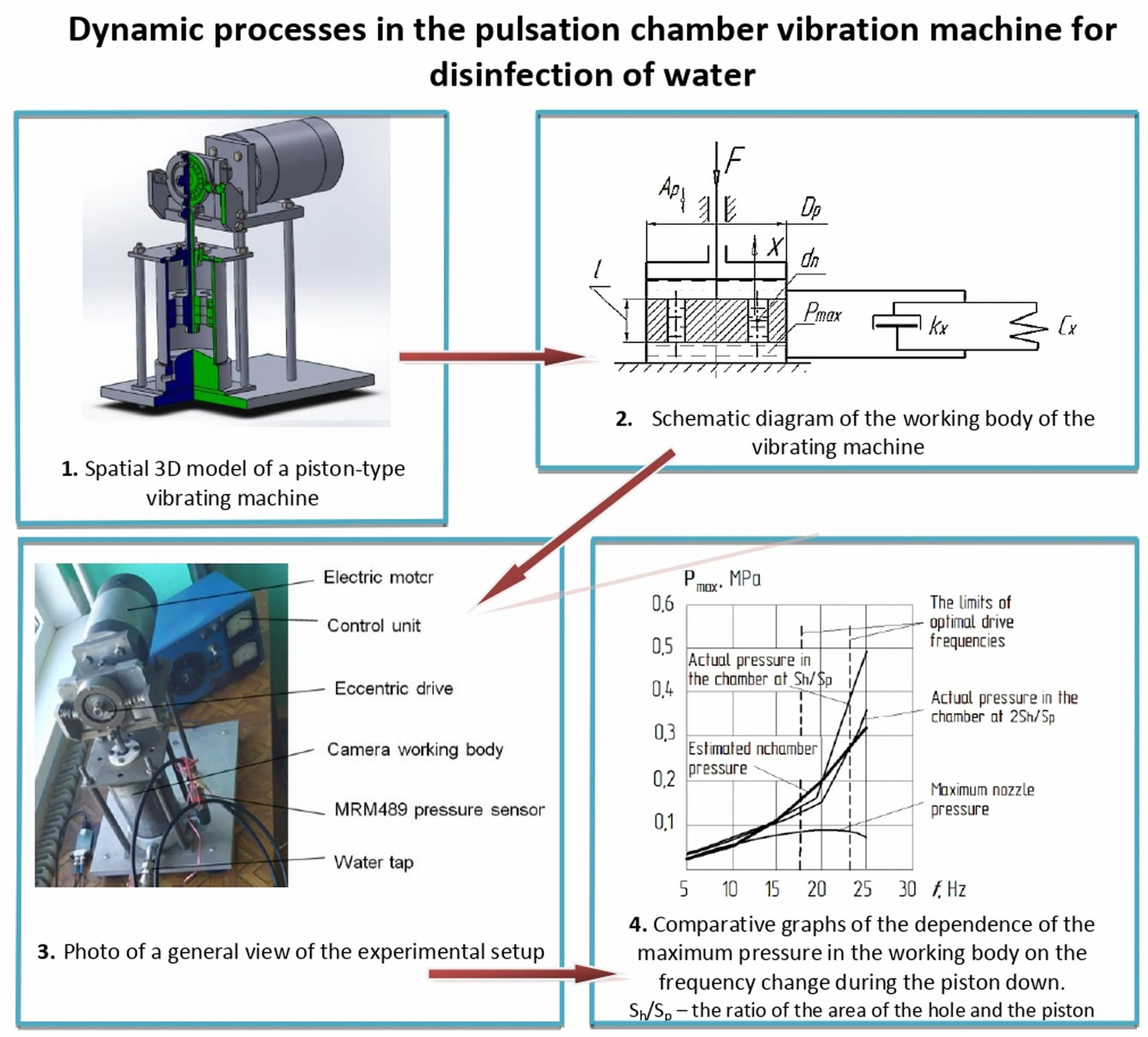
A vibrating machine for the disinfection of an aqueous medium is built based on an eccentric vibration drive, in which the vibration amplitude does not depend on the vibration frequency [14] and contains a working body, a pulsation chamber – a cylindrical container, into which a piston with a hole is inserted, connected by a rod with an eccentric vibration drive (Fig. 2).
Optimum performance of the disinfection process is achieved at the highest pressure in the pulsation chamber with the downstroke of the piston and the maximum pressure of the fluid flowing out of the hole. Therefore, the change in the maximum pressure in the pulsation chamber was taken as a criterion for the performance of the drive of the vibration machine, taking into account the highest pressure of the jet at the outlet from the hole in the piston during its downward movement.
Fig. 2Spatial 3-D model of a piston-type vibrating machine
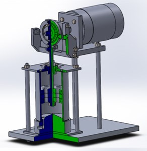
Fig. 3Schematic diagram of the working body of the vibrating machine
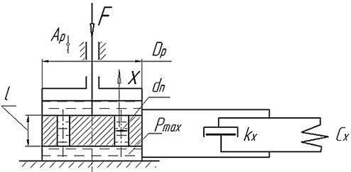
To study the dynamics of the maximum pressure change from the design parameters of the working body of the vibration machine and the operating modes of its drive on the basis of the schematic diagram of the working body of the vibration machine (Fig. 3), an analytical model is proposed, when the liquid moves through the hole in the piston at the stage of its downward movement Eq. (1).
The first equation of system Eq. (1) describes the moving of the fluid volume from the pulsation chamber through the hole during the downward stroke of the piston, taking into account the constriction of the flow at the inlet to the hole. The second equation of system Eq. (1) represents the steady motion of the oscillatory system, under the action of the exciting force of the drive .
The first term of the equation on the left side characterizes the forces of inertia of the oscillating mass of the fluid and piston, the second term of the equation – is the forces of internal viscous resistance and the third term of the equation – is the restoring forces of elastic bonds. On the right side of the equation, the term represents the perturbing drive force:
where – is the force acting on the rod of the working body; – is the mass of the liquid that will receive oscillatory motion; – is the piston diameter; – hole area; – is the area of the piston; – piston vibration amplitude; – amplitude of fluid oscillation in the hole; – maximum pressure in the pulsation chamber during the down stroke of the piston; of the piston; – is the rigidity of the elastic medium of the liquid with bubbles, taking into account the elasticity of the cylinder; – damping coefficient; – accounting factor narrowing the fluid flow in the hole, 0, 6 [15].
When analyzing the dynamic model, the following assumptions were used for the downward movement of the piston: the law of fluid continuity operates in the fluid, taking into account the narrowing of the flow when it flows through the hole; water temperature 20 °C, the amount of dissolved air is taken into account.
The study of the change in the maximum fluid pressure in the pulsation chamber during the downward stroke of the piston was carried out depending on the operating modes of the drive and the design parameters of the vibration machine: – frequency of oscillations of the piston; – amplitudes of piston oscillations; – hole diameter (at 100 mm – piston diameter) and the ratio of their areas . In an analytical study, the maximum pressure in the pulsation chamber was determined during the downward stroke of the piston.
From the first equation of system Eq. (1), we can write the following dependence:
where is the amplitude of fluid oscillations in the hole; is the amplitude of fluid vibrations in the hole; – piston vibration amplitude; – hole diameter.
Then the fluid velocity in the hole is determined by the following relationship:
where – vibration frequency, Hz.
The acceleration of the fluid in the hole is determined by the following relationship:
Taking into account that the force on the piston rod during the oscillation cycle varies from zero to the maximum value and creates the maximum fluid pressure in the pulsation chamber, during the downward stroke of the piston, the second equation of system Eq. (1) can be written as follows:
After transforming, we get the equation for determining the maximum pressure:
The damping capacity of the piston with a hole , the rigidity of the elastic medium of the liquid, taking into account the gas component and taking into account the elasticity of the cylinder , can be found by the formulas Eqs. (7), (8):
where – dynamic coefficient of density, 8,94×10⁻⁴ Pа·s; – length of hole, 0,045 m; – number of holes, 1.
The stiffness of the elastic medium of a liquid with the inclusion of a gas component and taking into account the elasticity of the cylinder is determined by the dependence:
where – bulk modulus of the gas component; – the modulus of elasticity of the material of the walls of the cylinder, 2×10¹¹ Pа); – thickness of cylinder wall, 5 mm; – diameter of the piston.
The effect of dissolved air on the elasticity of a liquid (water) is given by D.N. Popov [16] in the following form:
where – bulk modulus of fluid (for water 20×108 Pа); – air volume; – fluid volume; – atmosphere pressure; – absolute pressure in the working body; – adiabatic exponent (for air 1, 4).
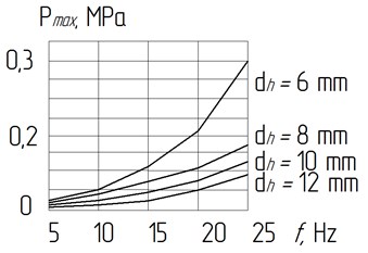
Eq. (6) makes it possible to evaluate the effect of various parameters on the pressure when the piston moves downward (liquid compression) with a change in the pulsation frequency. Using the MtchCad software product, calculations were carried out according to equation (6) and a graph was constructed of the dependence of the pressure value on the oscillation frequency with a change in the size of the hole diameter Fig. 4.
As a result of analytical studies, it was found that with an increase in the oscillation frequency, the maximum pressure in the pulsation chamber increases. It was also found that with an increase in the oscillation frequency and a decrease in the diameter of the hole, the maximum pressure in the pulsation chamber increases.
It should be noted that with an increase in the piston diameter, the inertial parameters of the machine will increase, which will lead to an increase in the reactive mass (the base of the machine), and energy costs will increase. By reducing the diameter of the hole, with a certain diameter of the piston, the flow rate of liquid through the hole will decrease, as a result of which the disinfection process will decrease.
Therefore, in further experimental studies of the real change in the maximum pressure from the design parameters and operating modes of the drive, the task was to determine the frequency boundaries of the drive and the ratio of the area of the hole to the area of the piston .
Fig. 4Graphs of the dependence of the pressure Pmax during the piston downward in the fluid on the oscillation frequency f when the diameter of the hole d changes: the oscillation amplitude Ap= 2 mm; piston diameter Dp= 100 mm; the mass of fluid that fluctuates, m= 0,2 kg
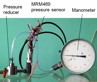
For research, the experimental setup (Fig. 5) was equipped with an MPM489 pressure sensor, which was pre-calibrated on a special stand (Fig. 6) using a pneumatic compressor and using an electronic oscilloscope with the “DiSco” USB software on a personal computer.
Fig. 5Photo of a general view of the experimental setup
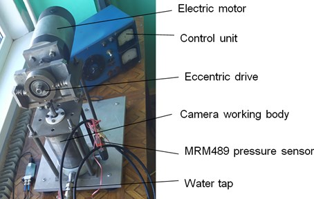
Fig. 6Photo of a general view of a tare stand
To measure the instantaneous value of the hydrodynamic pressure in the pulsation chamber, an MRM489 piezoresistive pressure sensor (Fig. 5) and a BM8020 USB oscilloscope are used, which is connected to a personal computer via a USB port and served by the “DiSco” software product.
The results of experimental studies of changes in the maximum pressure in the working body of a vibrating machine are obtained in the form of the waveform in Fig. 7.
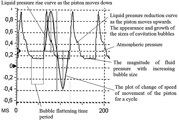
An analysis of the obtained oscillograms showed that the maximum pressure of the compression shock wave and the maximum pressure below atmospheric are not symmetrical to the change in the piston speed (Fig. 7, Fig. 8). From the oscillogram of Fig. 8 it can be seen that when the piston moves upward, the decrease in the maximum pressure below atmospheric has a period of constant magnitude, which is explained by the appearance of cavitation bubbles and an increase in their size during this period.
The waveforms were processed using a calibration graph and the dependences of the maximum pressure on the frequency and changes in the ratio of the hole area to the area of the piston during the piston stroke downward Fig. 9 and upward Fig. 10 were plotted.
Fig. 7Screenshot of the waveform of the change in maximum pressure in the working body
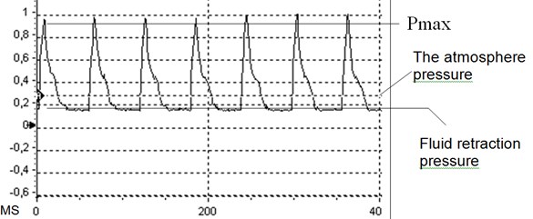
Fig. 8Screenshot of the processed waveform of the maximum pressure in the working body
Comparing the obtained dependences (Fig. 9), it was found that with an increase in the oscillation frequency of the piston in the working fluid, the maximum fluid pressure increases, but an increase in the ratio of the hole area to the piston area twice leads to a decrease in the maximum pressure by 0,1 MPa at the same frequency, which leads to a decrease in the intensity of disinfection.
Also, to determine the full picture of the process, the maximum pressure of the jet flowing from the hole was measured by the sensor. Its dependence on the oscillation frequency is shown in Fig. 9 (lower curve).
This curve characterizes the amount of fluid flow through the hole. It was found that with an increase in the oscillation frequency from 18 Hz, the volume of bubbles in the working body of the vibrating machine significantly increases; later, when the piston moves down, they disappear and lead to a decrease in fluid flow through the hole, which leads to a decrease in the pressure of the jet from the hole.
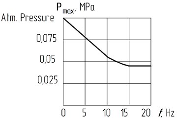
Fig. 10 shows the experimental dependence of the change in the maximum liquid pressure relative to atmospheric pressure during the upward stroke of the piston. It was established that with an increase in frequency to 13 Hz, the maximum pressure in the working body drops to 0,05 MPa, and with a further increase in the frequency of oscillations of the drive, the pressure in the working body stabilizes at 0,04 MPa.
Based on the analysis of the described phenomena, it is recommended to choose the frequency range of the vibrations of the working body of the vibrating machine in the range from 18 to 23 Hz, when the maximum pressure is still significant and the decrease in fluid flow through the hole is not significant.
Fig. 9Comparative graphs of the dependence of the maximum pressure in the working body on the frequency change during the piston stroke down: A= 0,002 m; Dp= 0,1 m; dh= 0,006 m; Sh/Sp – the ratio of the area of the hole and the piston
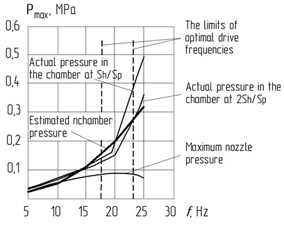
Fig. 10The dependence of the maximum pressure drop in the working body on the frequency change during the upward stroke of the piston: A= 0,002 m; Dp= 0,1 m; dh= 0,006 m
To visualize the picture of the fluid flowing through the hole in the oscillatory mode and to identify the process of occurrence of cavitation processes, an experimental setup with a transparent channel was created and high-speed video recording of the reciprocating movement of the liquid through the hole was carried out. Photographs of the process were obtained during the passage of a liquid through an opening with a cross-section of 10×10 mm with oscillations at frequencies from 0 to 24 Hz with amplitude of 2 mm and a piston diameter of 100 mm (Fig. 11-12).
At the stage of the upward stroke of the piston, the maximum pressure drops below atmospheric and in the liquid, which is drawn into the pulsation chamber with a vibration frequency Hz (Fig. 11), a cavitation cavity appears at the entrance to the hole, and a swarm of cavitation bubbles is observed in the pulsation chamber.
Fig. 11Photograph of a transparent channel with liquid at the moment of drawing the liquid into the pulsation chamber: the appearance of a cavitation cavity and cavitation bubbles at an oscillation frequency of 20 Hz
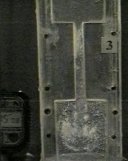
Fig. 12Photograph of a transparent channel with liquid at the moment of expulsion of the liquid from the pulsation chamber: the appearance of a cavitation cavity at an oscillation frequency of 20 Hz
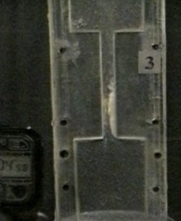
At the stage of the downward stroke of the piston, the maximum pressure in the working fluid increases and a cavitation cavity is observed at the inlet in the lower part of the hole (Fig. 13), and also a small number of bubbles filled with compressed gas are observed in the pulsation chamber. This leads to a slight decrease in the volumetric elasticity of the liquid in the pulsation chamber and to a decrease in the volume of liquid that passes through the hole (the flow rate of the liquid through the hole decreases, which leads to a decrease in the mixing of the liquid in the working organ and, accordingly, a decrease in the performance of the disinfection process).
As a result of studies on visualizing the process of reciprocating fluid flow through the hole, it was found that depending on the frequency and amplitude of vibrations, the selection of the structural parameters of the working body, cavitation processes occur in the liquid that is characterized by the maximum pressure in the working body and confirm the amplitude and frequency nature of the change maximum pressure obtained by analytical studies.
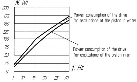
When conducting experimental studies, it was also established the amount of energy consumption about the vibrating machine by measuring the electrical characteristics presented on the drive motor. From the graph of Fig. 12 it can be seen that at piston vibration frequencies from 18 to 25 Hz, energy consumption is in the range from 125 to 150 Wt, which indicates insignificant energy costs for the disinfection process.
The results of analytical and experimental studies of the dynamics of the vibration drive of the machine for disinfecting water made it possible to formulate recommendations on the selection of the design parameters of the working body and identify the frequency boundaries of the operating modes of the drive of vibrating machines for disinfection of liquid media.
Fig. 13Power consumption graphs of a vibrating machine drive
4. Conclusions
1) It has been established that with an increase in the frequency of piston oscillations, the maximum pressure in the working body chamber increases with the occurrence of the effect of water hammer, and with an increase in the ratio of the hole area to the piston area leads to a decrease in the maximum pressure in the working body chamber.
2) An increase in the maximum pressure with a decrease in the diameter of the hole has different consequences: on the one hand, an increase in the maximum pressure, which leads to more active destruction of microbes, and on the other hand, the volume of liquid flowing through the hole decreases, which leads to a decrease in the productivity of the process.
3) Process Imaging Research reciprocating fluid flow through the orifice showed that the maximum pressure in the pulsation chamber and the effect of the appearance of cavities shown at frequencies of 18 to 23 Hz.
4) To drive the working body of a vibrating machine with a piston diameter of 100 mm and a hole diameter of 6-8 mm, the following modes are recommended: vibration amplitude 2 mm, piston vibration frequency in the range from 18 to 23 Hz.
5) When examining the surface of the hole and the surface of the pulsation chamber, after more than 400 hours of operation of the vibration machine, no traces of cavitation corrosion were found. Cavitation model, based on the maximum pressures obtained, is an early stage of gas-steam cavitation.
6) The proposed design of a vibration machine is not difficult to construct with the use of unified elements and the transition to industrial production does not require significant costs and design changes.
7) The use of the cavitation process of water disinfection without chemical reagents will reduce the carcinogenicity of the final composition of water.
References
-
Znak Z. O., Suhatsky Yu V., Mnykh R. V. Development of the cavitation-flotation process of sewage treatment in the aspect of the realization of modern concepts of synthesis of chemical-technological systems. Bulletin Lviv Polytechnic National University, Vol. 787, 2014, p. 75-79.
-
Sangave P. C., Pandit A. B. Ultrasound and enzyme assisted biodegradation of distillery wastewater. Journal of Environmental Management, Vol. 80, 2006, p. 36-46.
-
Guo Z., Feng R. Ultrasonic irradiation-induced degradation of low-concentration bisphenol A in aqueous solution. Journal of Hazardous Materials, Vol. 163, 2009, p. 855-860.
-
Petrenko N. F., Mokienko A. V., Platov C. M. New technologies of water oxidation and disinfection advanced oxidation processes (literature review). Actual Problems of Transport Medicine, Vol. 2, Issue 52, 2018, p. 22-31.
-
Dolinsky A. A., Avdeeva Yu L., Zhukotsky E. K., Makarenko A. A. The use of cavitation technologies in the processing of liquid heterogeneous systems. Odessa National Academy of Food Technology, Vol. 45, Issue 3, 2014, p. 9-13.
-
Vitenko T. M. Hydrodynamic Cavitation in Mass Exchange Chemical and Biological Processes. Monograph, Ternopil, 2009, p. 224.
-
Ashokkumar M. Theoretical and Еxperimental Sonochemistry Involving Inorganic Systems. Science+Business Media B. V., Springer, 2011, p. 404.
-
Gultekin I., Ince N. H. Ultrasonic destruction of bisphenol-A: the operating parameters. Ultrasonics Sonochemistry, Vol. 15, 2008, p. 524-529.
-
Nasseri S., Vaezi F., Mahvi A. H., Nabizadeh R., Haddadi S. Determination of the ultrasonic effectiveness in advanced wastewater treatment. Iran Journal of Environmental Health Science and Engineering, Vol. 3, 2006, p. 109-116.
-
Silin R. I., Hordieiev A. I. Vibration Equipment Based on a Hydropulsator. Monograph, KhNU, Khmelnytskyi, 2007, p. 386.
-
Silin R. I., Hordieiev A. I., Paraska G. B., Parkhomenko V. D., Kravchuk V. V. Innovative Nanotechnologies of Activation and Disinfection of Water and Vibration Equipment. KhmTSNII, Khmelnytskyi, 2013, p. 252.
-
Shevchuk L. I., Aftanaziv I. S., Strogan O. I., Starchevsky V. L. Low-Frequency Vibration Resonance Cavitators. Publishing House of Lviv Polytechnic, 2013, p. 176.
-
Radomir Silin, Anatolij Hordieiev, Algimantas Bubulis, Vytautas Jurenas Vibrating Device for Sewage and Decontamination. Patent 5773, C02F 1/34 / Kaunas University of Technology, 2011.
-
Hordieiev А. І., Kostyuk N. O. IPC С02F 1/00, Vibrating Machine for Decontamination of Aquatic Environments. Patent for Utility Model No. 126495 of Ukraine, 2018.
-
Altshul A. D. Hydraulic Resistances. Nedra, Moscow, 1982, p. 224.
-
Popov D. N. Non-Stationary Hydromechanical Processes. Mechanical Engineering, 1982, p. 240.
About this article

