Abstract
In view of the design problem of the working amplitude and working frequency of vibrating icebreaking machine, the stiffness and damping value of the ice-snow was identified with the mechanical vibration theory and finite element method. The two-degree-of-freedom mathematical model was established in this paper. And numerical simulation was performed. Then the related icebreaking experiment was carried out. A lot of test and experiment results had proved that experimental data was consistent with the theoretical analysis of mathematical model of vibrating icebreaking system. It was confirmed that the correctness of vibrating icebreaking system’s mathematical model and the rationality of its design could be proved.
1. Introduction
Perpetual snow not swept away timely on the ground will turn into compacted ice-snow, which makes it hard to clean up. With the development and prosperous of urban transportation, the ice-snow on the ground commonly seen in north of China in winter does more and more harm to city road traffic, and it’s the key factor causing traffic accident often occurring in highway, airport and urban roads. So, the research on the urban road icebreaker is becoming an extremely urgent mission.
In the view of physical icebreaking, the using of vibration icebreaking machine is no doubt a very effective method. However, seldom achievements of research on parameters design about system’s working amplitude and frequency appeared, because of the complicated road condition which makes the frozen soil contacting stiffness identification hard.
For many years, scholars did some research on complex dynamic phenomena of vibration utilization machinery systems and had certain achievements. Liu Changsheng [1] gave analysis and calculation in detail on the vibrating mechanisms in L50 loader, such as deicing drum, cavel, hydraulic system, vibrating shaft and eccentric block, etc., and its effect of deicing is prospected. Yu Wenbing [2] think that the two most common snow and ice removal methods are mechanical clearance and chemical melting, and the advantages and disadvantages of each approach are discussed in his paper, including environmental and structural damage caused by corrosive snow melting. Brian E. [3] used with turbulence-modeling, particle-tracking, and cutting-edge approximations to solve Reynolds-averaged Navier-Stokes equations are numerically. Results suggest snow can be divided into splash and snow cloud when engineering treatments to improve visibility for snowplow drivers and following traffic. Wang Jiefu [4] did a tool-icebreaking experiment, and measured the tool-icebreaking static and dynamic force, vibrating frequency and amplitude. The stress and strain of the tool in the working process is analyzed in addition using the finite element theory. The conclusion is obtained that vibrating icebreaking using variable frequency in corresponding with the thickness change of ice is the best method for deicing. In this paper, the two-degree-of-freedom mathematical model of vibration icebreaking system was established. The stiffness and damping value of the system was confirmed by the finite element theory. And the numerical simulation of the system was performed. Then icebreaking experiment was carried out with its amplitude results matched the simulation ones, which confirmed the correctness of vibrating icebreaking system’s mathematical model and the rationality of its design.
2. Working principle of vibrating icebreaking system
The main structure of vibrating icebreaking system is shown in Fig. 1, which consists of power mechanism (1), transmission mechanism (2-5), actuator (6, 9) and support mechanism (7, 8). When it works, the motor (1) provide power through the transfer behavior of belt (2) for vibratory shaft (3) rotating at high speed together with eccentric block (4, 5), which can generate eccentric force acting on vibrating wheel (6) and skate (9) for their vibration. The vibrating skate (9) produces impact and shear force on the ice-snow for its crushing. The technical characteristics of the system are as follows in Table 1.
Fig. 1The main structure diagram of vibration icebreaking system: 1-motor, 2-belt, 3-vibrating shaft, 4-adjustable eccentric block, 5-fixed eccentric block, 6-vibrating wheel, 7-outer frame, 8-shock absorption rubber, 9-skate
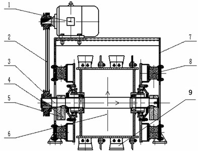
Table 1The technical characteristics table of vibration icebreaking system
Name | Quantity | Unit |
Working amplitude | 2.5 | mm |
Working frequency | 1000 | r/min |
Power | 3.9 | kw |
Deicing width | 1.5 | m |
Equipment weight | 661.3 | kg |
Torque | 30.043 | N·m |
3. The dynamic analysis of vibration icebreaking system
3.1. Mathematical model
On the basis of reference [5], the vibrating icebreaking system is usually simplified to two-degree-of-freedom mathematical model, as shown in Fig. 2. The two-degree-of-freedom mathematical model can reflect the dynamic response of the vibrating icebreaking system basically, and the solution is simple in Mathematics. According to the mathematical model as shown in Fig. 2, the motion equation of vibrating icebreaking system can be got.
To establish the mathematical model of vibrating icebreaking system, hypothesis of some parameters and conditions are put forward as follows:
1) Assume that ice-snow on the ground is elastic material of which the stiffness is , the damping coefficient is .
2) The vibrating icebreaking system is simplified as two mass units, namely upper mass unit and lower mass unit. The mass of upper mass unit and lower mass unit is and respectively. The upper mass unit includes outer frame (Fig. 1, Unit 7) and motor (Fig. 1, Unit 1). The lower mass unit includes vibrating shaft (Figure 1, Unit 3), adjustable eccentric block (Fig. 1, Unit 4), fixed eccentric block (Fig. 1, Unit 5), vibrating wheel (Fig. 1, Unit 6), outer frame (Fig. 1, Unit 7), shock absorption rubber (Fig. 1, Unit 8) and skate (Fig. 1, Unit 9).
3) When it works, the skate (Fig. 1, Unit 9) on the vibration wheel (Fig. 1, Unit 6) always keep contaction with ice-snow.
Fig. 2The mathematical model of vibration icebreaking system
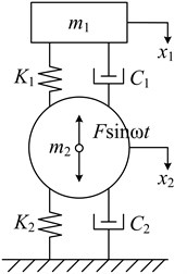
Based on the mathematical model above, the vibration differential equations describing its movement is as follows:
where, – exciting force, unit: N,
– working angular frequency, unit: rad/s,
– stiffness of shock absorption rubber, unit: N/m,
– stiffness of ice-snow, unit: N/m,
– damping of shock absorption rubber, unit: N·s/m,
– damping of ice-snow, unit: N·s/m.
The solution of differential Eq. (1) can be obtained. The amplitude and of upper mass unit and lower mass unit under the effect of exciting force are as follows:
where, – phase angle between exciting force and displacement of upper mass unit, unit: rad,
– phase angle between exciting force and displacement of lower mass unit, unit: rad:
The natural frequency of vibrating icebreaking system can be obtained as follows:
As is described in Eq. (2), the working amplitude of lower mass unit of the system is related with the stiffness and damping of shock absorption rubber and ice-snow. On the basis of reference [5], the stiffness and damping of shock absorption rubber are calculated. The stiffness and damping of ice-snow are associated with the composition, physical characteristics and frozen condition of the ice snow. So how to identify the stiffness and damping value of ice-snow is very important for the research on the dynamic characteristic (especially amplitude) of the vibrating icebreaking system.
3.2. The identification of system’s stiffness
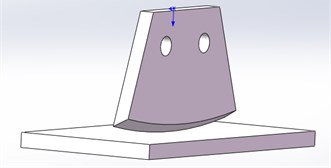
To obtain the stiffness of vibration icebreaking system, the model of interaction between skate and ice was established, as was shown in Fig. 3. The size of skate unit was defined in the practical value, while one of ice layer was 200×100×10 mm. The interaction unit was a circular-arc wedge-shaped surface. The knifepoint coincides with the center point of in bottom surface of the ice entity, and the interaction unit was parallel to the long edge of the ice layer.
Fig. 3The model diagram of skate contacting with ice surface
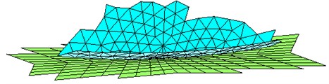
The material elasticity modulus of skate was given as 2.06×10¹¹ Pa, and Poisson's ratio as 0.26. Gotten from Reference [6], material elasticity modulus of ice was given as 2×10⁹ Pa and Poisson's ratio as 0.3. The two materials’ coefficient of friction was 0.02. SOLID186 cell was used to mesh the entity, and the mesh density was increased in the key area. The possible contacting points of skate bottom and ice were chosen to create contact pair [7-9], as was shown in Fig. 4.
Fig. 4The diagram of contact pair
According to the design size, the exciting force of vibrating icebreaking system could be gained as follows [10]:
where, – mass of the eccentric block, unit: Kg,
– working angular frequency, unit: rad/s,
– eccentric distance, unit: m.
There were four skates acting on ice surface every moment, and the impact force of each skate on ice was as follows:
where, – total exciting force caused by the rotation of eccentric block.
The ice entity was fixed, while the skate was restricted in and direction and could move only in direction. The downward exciting force of key point in skate on ice was 2414 N. The process of applying load was shown in Fig. 5.
Fig. 5The diagram of applied load
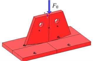
The practical interface between skate and ice was complex. Considering the stiffness’ variability of system, variable load was applied on the skate and its corresponding displacement was measured. Assuming that the load was and displacement was , the stiffness can be obtained as follows:
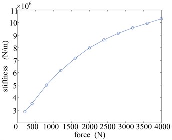
As was shown in Fig. 6 (F-d), as the force increases, the original displacement grows rapidly until 0.15 mm, after which the displacement was linear related to the force. The Fig. 6 (F-s) showed that the stiffness rose with the force increasing, because of the changeable contacting condition in corresponding with the increasing contact area. So, the stiffness should be selected according to the practical exciting force.
Fig. 6The curve of a) force-displacement (F-d) and b) force-stiffness (F-s)
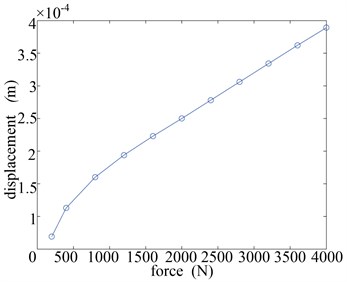
a)
b)
The Fig. 6 (F-s) indicated that under the action of single skate whose displacement was 0.279×10⁻³ m, the system’s stiffness was as follows:
The four skates acted on the ice in parallel, so the stiffness value of ice-snow was calculated as follows:
3.3. The identification of system’s damping value
After being frozen and impacted again, the melted ice-snow turned into ice with additive dust, freestone and air, etc. The component of ice on the ground was so complex that its structure distinguished greatly.
To estimate the damping value , with the reference to experimental data of frozen soil, the damping ratio of ice on the ground was selected as follows [11, 12]:
And the damping value of ice-snow was obtained as:
3.4. The dynamic analysis of icebreaking system
According to the actual design size of the vibrating icebreaking system, the related parameters of the system could be got. According to the different values of the stiffness , damping and working frequency , the curve of the amplitude of upper mass unit and lower mass unit could be obtained. Then the dynamic performance of the system was analyzed.
When the stiffness value of the system was 3.46×10⁷ N/m, the damping was 2.96×10⁴ N·s/m, and the other parameters were taken as the initial design value, Fig. 7 was the amplitude of upper mass unit and lower mass unit of vibrating icebreaking system variation with the changing of rotation speed . To make a qualitative analysis, the rotation speed was valued from 0 to 2500 r/min, of which the relationship with working angular frequency was as follows:
Fig. 7The curve of x1 – n, x2 – n
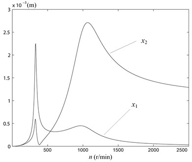
As could be seen from Fig. 7, the amplitude and increased rapidly while the rotation speed increased from 0 r/min gradually. When the rotation speed was about 350 r/min, it closed to the first-order natural frequency. At this time the amplitude value was large, and the resonance occurred. The maximum amplitude value of lower mass unit was got as about 0.6×10⁻³ m under the affection of damping value. When the rotation speed of the system further increased to 1100 r/min, it closed to the second-order natural frequency. At this time the maximum amplitude value of lower mass unit was got as about 2.7×10⁻³ m. And then, the amplitude began to decrease slowly. When the rotation speed was 1000 r/min (the rated speed of the motor), the amplitude value of lower mass unit was got as about 2.57×10⁻³ m. It closed to the design amplitude 2.5×10⁻³ m. At the same time, the amplitude value of upper mass unit x1 was got as about 0.46×10⁻³ m. The vibration isolation rate was 82 %. The effect of vibration isolation was very well.
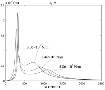
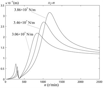
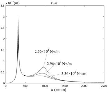
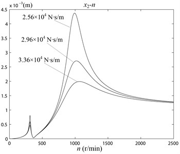
In the working status, the skate (Fig. 1, Unit 9) on the vibrating wheel (Fig. 1, Unit 6) contacted with the ice. Its working amplitude was affected by the stiffness of the ice. Because of each ice-snow road condition was not identical, the state of the contaction changed every time. The stiffness and damping of the ice-snow had great randomness. The response of working amplitudes of vibrating icebreaking system should be studied when the stiffness and damping varied in a certain range. When the stiffness 3.06×10⁷ N/m, 3.46×10⁷ N/m, 3.86×10⁷ N/m, the relationship curve of the amplitude , and rotation speed n was as shown in Fig. 8. When the damping 2.56×10⁴ N·s/m, 2.96×10⁴ N·s/m, 3.36×10⁴ N·s/m, the relationship curve of the amplitude , and rotation speed n was as shown in Fig. 9.
Fig. 8The curve of x1 – n, x2 – n with different stiffness K2 values
a)
b)
Fig. 9The curve of x1 – n, x2 – n with different damping C2 values
a)
b)
From Fig. 8 and Fig. 9 could be seen, the natural frequency of vibrating icebreaking system and the amplitude , would be larger with the increasing of stiffness . It has no significant effect on the natural frequencies of the system with the increasing of damping of . But it would make the amplitude , became smaller. In the actual working conditions, the skates (Fig. 1, Unit 9) on the vibrating wheel (Fig. 1, Unit 6) were not always contact with the ice-snow in close. And the ice might already be broken. So, the stiffness and damping value of the ice-snow would have some changes [13, 14]. But from the simulation results, the changes in the stiffness and damping of the system within a certain range was limited on the effect of the amplitude of lower mass unit . The actual road conditions were very complex, so the analysis above was qualitative analysis. Only by lots of experiments, the reliable parameters of vibrating icebreaking system could be obtained.
3.5. The analysis of icebreaking capability
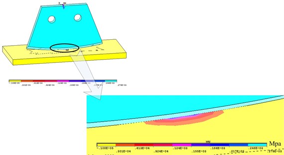
As could be seen from Fig. 5, partial enlarged drawing of the ice deformation was as shown in Fig. 10, after the load was applied.
Fig. 10The partial enlarged drawing of the ice deformation
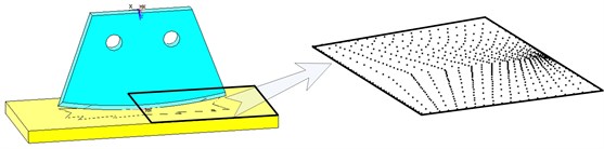
The overall structure and the grid partition were both symmetric about the - plane, so the node stress was symmetrical too. Therefore, it was only needed to select the half of the nodes on the ice, as shown in Fig. 11. The stress of the nodes would be calculated.
Fig. 11The schematic diagram of the nodes on the ice
The stress average value of these nodes was calculated. The three-principal stress was respectively:
Because the ice was brittle material, the second strength theory [15] was used to verify the compression state. The fracture criterion which was established by the second strength theory was:
where, – Poisson’s ratio, 0.3, – breaking point, unit: Pa.
Substitute Eq. (6) into Eq. (7):
The compressive strength of compacted ice-snow [15] was shown in Table 2.
Table 2The compressive strength of ice-snow
The type of ice-snow | The density of ice-snow (Kg/m3) | The compressive strength (MPa –1 –20℃) |
The compacted snow | 450-750 | 0.2-1.67 |
Ice | 750-900 | 0.9-2.94 |
The compacted ice | More than 900 | 1.0-4.0 |
We could see from Table 2, the maximum compressive strength of ice could be reached 4.0 MPa. So 4.0×10⁶ Pa. It was far less than the requirements of criteria 4.09×10⁷ Pa. So, the compressive strength of ice was insufficient. It would be broken. So, the icebreaking capability of vibrating icebreaking system was able to meet the requirement.
4. The experimental analysis of icebreaking system
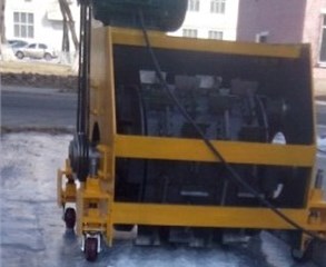
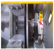
The test-bed was built on the icebreaking system, as was shown in Fig. 12. The test point in on the side plate (Fig. 1, Unit 6) and outer frame (Fig. 1, Unit 7). The experiment instrument was consisted of acceleration sensor including B&K4508B and B&K4517, of modal force-hammer including B&K and PCB, and of data acquisition equipment including B&K3560-D 32 channel forepart and BK3560D portable analyzer.
Fig. 12The experiment graph of icebreaking system

a)
b)
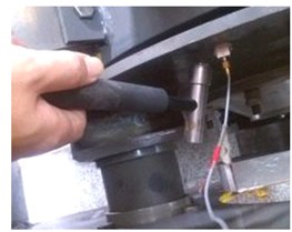
In the experiment, the primary object of investigation was the system’s practical working amplitude and damping effect of the rubber (Fig. 1, Unit 8). Select test point 1 on the vibration wheel where its amplitude was measured before vibration reduction, and on the outer frame select test point 2 near test point 1 where amplitude of outer frame was measured after vibration reduction. Clean up the area around the two test points and fix the sensors on two test points, as was shown in Fig. 13. Then lots of measurements were carried out.
The acceleration signals of sensor 1 and 2 were input through channel 1 and 2 of B&K. 3560-D 32 respectively. The double integral and FFT transform of the signals was carried on, after which the variable amplitude in corresponding with the change of frequency was displayed [16], as was shown in Fig. 14 and Fig. 15. Green line is the curve of amplitude in Figs. 14-15, and is the curve of amplitude ratio in Fig. 16. At the same time, the red line is only the auxiliary line in Figs. 14-16.
Fig. 13The graph of test point 1 and test point 2
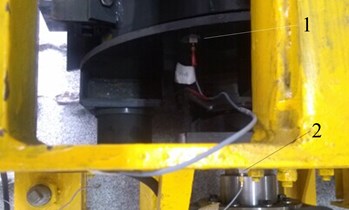
Fig. 14The curve of amplitude in test point 1
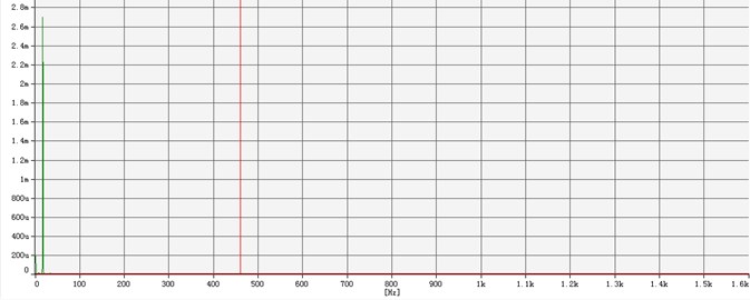
Fig. 15The curve of amplitude in test point 2
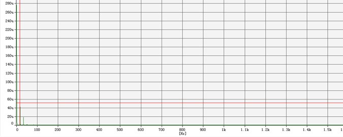
Fig. 14 and Fig. 15 showed that the maximum amplitude was achieved when the icebreaking system works at the frequency of 16.6 Hz. The amplitude of test point 1 without damping measures was 2.65 mm, while one of test point 2 with damping measures was 51.6 μm. Considering the uncertain factors, such as the ice stiffness and damping value etc., the experimental amplitude was already close to the design one. The ratio which was gotten through the amplitude of test point 2 divided by the amplitude of test point 1 was displayed in Fig. 16, where axis , represent working frequency and the ratio respectively. The ratio curve demonstrates the effect of vibration reduction.
Fig. 16 indicated that the amplitude ratio changes as the frequency does. When the icebreaking system worked at the resonance frequency of 16.6 Hz, the effect of the vibrating reduction was very obvious with the amplitude ratio being 1.92 %.
In the experiment, the second object of investigation was to measure the system’s practical working frequency and attest whether it avoided the resonance frequency. Selected a test point on the side plate of vibrating wheel (Fig. 1, Unit 6), where the acceleration sensor was fixed, as was shown in Fig. 17.
Fig. 16The curve of amplitude ratio
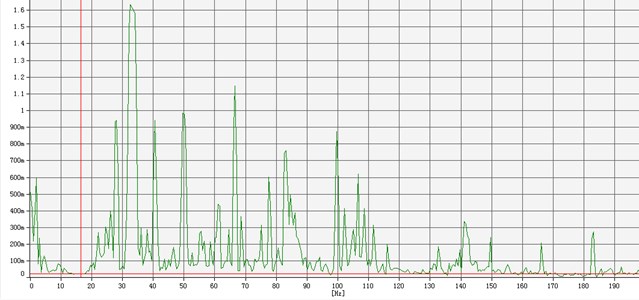
Fig. 17The graph of modal test
a)
b)
To achieve the responding signal and study on the inherent characteristics of the system used the force hammer to hit the side plate somewhere around the test point as the exciting signal. The operation process should be smooth and nimble to avoid the interference between the exciting and responding signals. When the forepart of B&K. 3560-D 32 began collecting signal, the hitting process was operated for 5 times with interval of 10 s-20 s every time. The five responding signals collected were compared, and the best one was saved [17-19].
The exciting and responding signals were analyzed in BK3560D portable analyzer, and the transfer function of the natural frequency was obtained, as was shown in Fig. 18.
Fig. 18The curve of natural frequency’s transfer function
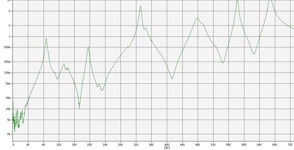
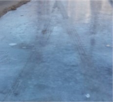
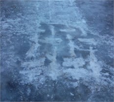
As was shown in Fig. 18, because of the hitting force degree, velocity and accuracy, the curve of natural frequency’s transfer function at the low frequency was chaotic. The first big amplitude occurs at the frequency of 89 Hz, which was the natural frequency. The working speed of the icebreaking system was 1000 r/min, and the practical working frequency was 16.6 Hz, which was far away from the natural frequency which had a great influence on the amplitude. So, the system works smoothly and reliably at the remote resonance station. The effect of the icebreaking system was shown in Fig. 19. The left side was the ice on the ground in –20 centigrade, and the right one was the ice deiced by the system under the affection of its self-gravity and exciting force. It showed that the ice was well crushed by the icebreaking system.
Fig. 19The comparison photos of icebreaking in before and after
a)
b)
5. Conclusions
1) As was known from the practical working condition of the icebreaking system, the skate (Fig. 1, Unit 9) on the vibration wheel (Fig. 1, Unit 6) contacted with the ice directly. The stiffness and damping value in the system’s dynamic model was influenced greatly by the components and density of the ice on the ground, and the correctness of the theoretical model needed to be verified by the experiment results. By the comparison of experiment and simulation results, the experiment amplitude was in agreement with the simulation one, which certified the correctness of the system’s dynamic model and the feasibility of the method for solving stiffness and damping value in the model.
2) Vibrating icebreaking machine was a multiple-degree-of-freedom vibration system. It was simplified with a two-degree-of-freedom mathematical model in order to facilitate the calculation. A lot of test and experiment results had proved that experimental data was the basic consistent with the theoretical analysis of mathematical model of vibrating icebreaking system. It was clear that the two-degree-of-freedom mathematical model of vibrating icebreaking system was reliable, and that the related theoretical deduction was correct.
References
-
Liu Changsheng Design of vibration drum of highway deicing machine used in south China. Journal of Central South University of Forestry and Technology, Vol. 30, Vol. 9, 2010, p. 85-90, (in Chinese).
-
Yu Wenbing, Yi Xin, Guo Ming State of the art and practice of pavement anti-icing and de-icing techniques. Sciences in Cold and Arid Regions, Vol. 6, Issue 1, 2014, p. 14-21.
-
Brian E., Hany K. Modeling of airborne debris around overplow deflectors during high-speed snowplowing. Journal of Cold Regions Engineering, Vol. 16, Issue 3, 2002, p. 119-138.
-
Wang Jiefu Research on Mechanism of Snow-Ice Removing Using Vibration and Optimization of Vibration Roller. Jilin University, Jilin, China, 2004, (in Chinese).
-
Wen Bangchun, Wu Xinghua, Ding Qian, et al. The Nonlinear Dynamics Theory and Experiment of Fault Rotating Machinery. Science Press, Beijing, 2004, (in Chinese).
-
Li Zhijun, Wang Yongxue, Li Guangwei Experimental analysis of flexural strength and elastic modulus of the DUT-1 model ice. Advances in Water Science, Vol. 13, Issue 3, 2002, p. 292-297.
-
Vasudevan G., Kothandaraman S., Azhagarsamy S. Study on non-linear flexural behavior of reinforced concrete beams using ANSYS by discrete reinforcement modeling. Strength of Materials, Vol. 45, Issue 2, 2013, p. 231-241.
-
Zhou Pengzhan, Xiao Jiayu, Zeng Jingcheng, et al. Structural analysis of large-scale composite wind turbine blade based on ANSYS. Journal of National University of Defense Technology, Vol. 32, Issue 2, 2010, p. 46-50.
-
Ghadirian M., Hayes R. E., Mmbaga J., et al. On the simulation of hydrocyclones using CFD. Canadian Journal of Chemical Engineering, Vol. 91, Issue 5, 2013, p. 950-958.
-
Sun Xuejun, Li Keqiang, Wang Xiaofeng Study on an eccentric slide block balancing mechanism in a single-cylinder engine. Journal of Vibration and Shock, Vol. 26, Issue 7, 2007, p. 97-100.
-
Xu Chunhua, Xu Xueyan, Qiu Mingguo, et al. Experimental study on dynamic damping ratio of frozen soil under cyclic loading. Journal of Harbin University of Civil Engineering and Architecture, Vol. 35, Issue 6, 2002, p. 22-25, (in Chinese).
-
Kim Hyunsoo, Lee Chunju, Choi, Kyungsik, et al. Study on icebreaking performance of the Korea icebreaker ARAON in the arctic sea. International Journal of Naval Architecture and Ocean Engineering, Vol. 3, Issue 3, 2011, p. 208-215.
-
Glass B. J., Dave A., Mckay C. P., et al. Robotics and automation for “Icebreaker”. Journal of Field Robotics, Vol. 31, Issue 1, 2014, p. 192-205.
-
Li Yaqin, Wu Wenfu, Wang Junfa, et al. Study on parameter optimization of concave disc copying icebreaking snow sweeper. International Journal of Smart Home, Vol. 8, Issue 3, 2014, p. 197-206.
-
Liu Hongwen Material Mechanics Ι. Higher Education Press, Beijing, 2010, (in Chinese).
-
Kraftmakher Y. Principles of radio: a laboratory experiment. Physics Education, Vol. 37, Issue 5, 2002, p. 417-421.
-
Deng Xingqiao, Zhu Weibing, Chen Yonghong, et al. Optimal design for an end face engagement worm gear with multiple worm-wheel meshing. Chinese Journal of Mechanical Engineering, Vol. 1, Issue 30, 2017, p. 144-151.
-
Hollkamp J. J., Gordon R. W. Modal test experiences with a jet engine fan model. Journal of Sound and Vibration, Vol. 248, Issue 1, 2001, p. 151-165.
-
Krasnikovs A., Kononova O., Machanovskis A., et al. Characterization of mechanical properties by inverse technique for composite reinforced by knitted fabric. Part 2. Experimental evaluation of mechanical properties by frequency eigen values method. Journal Vibroengineering, Vol. 14, Issue 2, 2012, p. 691-698.
About this article

This work was financially supported by the National Natural Science Foundation of China for Young Scientists (Grant No. 51105065), the Fundamental Research Funds for the Central Universities from Ministry of Education of China (Grant No. N140304005, N160313003), National Science Foundation for Postdoctoral Scientists of China (Grant No. 2014M551105, 2015T80269).
Yang Liu and Bangchun Wen design effort of vibrating icebreaking system. Juqian Zhang responsible for dynamic analysis of vibrating icebreaking system. Qiang Ma, Chengdong Liu done experiment effort of vibrating icebreaking system.
