Abstract
We propose in this paper a method to detect cracks in circular plates clamped at the circumference. It consists in analyzing and interpreting the frequency changes that occur due to a circular arc crack. We show that the effect of the crack depends on the strain energy loss, which actually is proportional to the curvature achieved by the affected region in the radial direction. Three types of cracks are considered herein to demonstrate this dependency, differing by their length. Modal analysis is performed involving a professional simulation software for the intact plate, and that with the generated cracks. We found a perfect fit when we compared the curvature of the plate in the radial direction obtained with the analytical relation with the frequency values for the crack displaced along the radius. Therefore, using the curvature of several vibration modes we can obtain damage patterns that can be used to locate circular cracks.
1. Introduction
Vibration of circular plates became during the last decades an import issue in various engineering applications such as: aerospace, naval architecture or pressure vessels. Therefore, this subject received a significant amount of research [1-5]. Thus, transverse vibration of simply supported circular plates with elastic constrains was investigated by Navita and Leissa [6] or Laura et al. [7]. Irie et al. [8] studied the case of circular plates with elastic restrains along some radial segments. Grossi and Laura [9] have determined the lower frequency coefficients of polar orthotropic circular plates supporting concentrated masses, by involving the Rayleigh-Schmidt technique. Furthermore, Bercin [10] has obtained the natural frequency coefficients for clamped orthotropic plates by using Kantorovich’s method. Free vibration of circular plated\s with varying thickness, fixed to a Winkler foundation was solved by Laura and Gutierrez [11].
In this paper we analyzed the frequency changes which are occurring due to the appearance of a circular arc crack. Analyzing three types of cracks, we could conclude that the crack effect depends on the strain energy loss. Finally, by involving the curvature of several vibration modes, we show how damage patterns may be involved in the process of circular cracks detection.
2. Deflection and curvature of circular plates
Let us consider a circular plate as that represented in Fig. 1(a) to which we associated polar coordinates. If assuming harmonic vibration, the well-known equation of motion for free vibration of this plate is:
In Eq. (1), the mode shape amplitude is denoted , is the angular frequency and represents the time.
Fig. 1a) Circular plate with the polar coordinates and b) the circular plate with damage
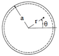
a)
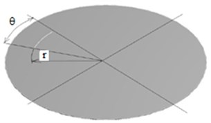
b)
Taking into consideration the classical differential equation of motion for the transverse displacement :
In Eq. (2) the term is the flexural rigidity, calculated with the mathematical relation:
where is Young’s modulus, is the plate thickness, is Poisson’s ratio and is the mass density. Note that:
is the Laplace operator. By substituting Eq. (1) into Eq. (2) results:
where we denote .
Because the origin of the coordinate system coincides with the center of the circular plate, the solution of Eq. (5) becomes:
where and are coefficients which determine the mode shape and are solved for from the boundary conditions Eq. (7). is the Bessel function of the first and kind, and is the modified Bessel function of the first kind [12]. The index corresponds to the number of nodal diameters.
The boundary conditions [3] are for , so it results:
When Eq. (6) is substituted into Eq. (7) it will be obtained the characteristic equation:
The roots of Eq. (8), namely ·a represents the square of dimensionless wave number. The dimensionless wave number () is express related to which refers to the number of nodal diameters and is the number of nodal circles.
For a simply supported circular plate, the normalized mode shape function is:
where:
3. Deriving the mode shapes curvatures from numerical simulation
The numerical simulation was performed by using finite element method, first for undamaged circular plates clamped all around, and then for damaged circular plates (Fig. 1(b)). The circular plate clamped all around is made of structural steel, with the external radius 0.4 m and the thickness 2 mm, having the Young’s modulus 2·1011 N/m2, the mass density 7850 kg/m3 and the Poisson’s coefficient 0.3.
The damage taken into account is of a circular shape with a wide angle of: 22.5 deg, 90 deg and 360 deg (Fig. 1(b)). The depth of damage is of 1 mm. The damage is moved along the whole radius of the circular plate.
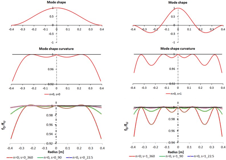
Fig. 2Comparison between analytic calculation and FEA analysis for n= 0, s= 0, 1
4. Comparison of the results
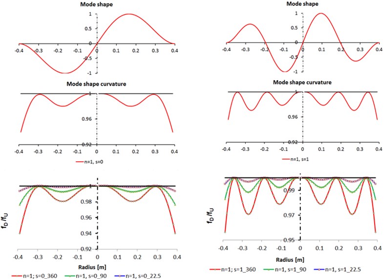
The analytic results of the mode shape for numbers of nodal diameter 0, 1 and numbers of nodal circles 0, 1 are presented in Figs. 2-3. Also, in this figures, for the same nodal numbers, are presented the comparison between analytic calculation of the mode shape curvatures and FEA analysis for the ratios between the natural frequencies for the damaged and undamaged circular plate ().
For 0, 0, 1 (Fig. 2) the mode shape (deflection) of circular plate had maximum value in the center of the plate and for 1, 0, 1 (Fig. 3) there is no deflection in the center of the plate. I can be observed that the mode shape curvatures for 0, 0 (Fig. 2) and 1, 0 (Fig. 3) are very similar, also for 0, 1 (Fig. 2) and 1, 1 (Fig. 3).
Fig. 3Comparison between analytic calculation and FEA analysis for n= 1, s= 0, 1
5. Conclusions
The ratios between the natural frequencies for the damaged and undamaged circular plate can be used to indicate the damage position and extent since for each damage case a specific sequence of frequency changes exist.
When the value of the damage angle is modified, the shape of the curve is the same by increasing the angle of damage the frequencies ratio. No significant frequency changes can be observed when the damage is located near the center of the circular plates.
Comparing the results from circular plate with the relationship obtained at beams [13] to calculate de modified frequency in damaged condition , that is:
we concluded that this relation can be applied for circular plates. In Eq. (11) we denoted the severity of the damage and with the mode shape curvature.
References
-
Mirkhalaf M. Transverse vibration of clamped and simply supported circular plates with an eccentric perforation and attached concentrated mass. Journal of Solids Mechanics, Vol. 1, 2009, p. 37-44.
-
Senjanovic I., Hadzic N., Vladimir N., Cho D. S. Natural vibrations of thick circular plate based on the modified Mindlin theory. Archives of Mechanics, Vol. 66, Issue 6, 2014, p. 389-409.
-
Tufoi M., Gillich G. R., Praisach Z. I., Ntakpe J. L., Hatiegan C. An analysis of the dynamic behaviour of circular plates from a damage detection perspective. Romanian Journal of Acoustics and Vibration, Vol. 11, Issue 1, 2014, p. 41-46.
-
Thakare S. B., Damale A. V. Free vibration of circular plates with holes and cutouts. IOSR Journal of Mechanical and Civil Engineering, Vol. 8, Issue 2, 2013, p. 46-54.
-
Wei G. W., Zhao Y. B., Xiang Y. The determination of natural frequencies of rectangular plates with mixed boundary conditions by discrete singular convolution. International Journal of Mechanical Sciences, Vol. 43, 2001, p. 1731-1746.
-
Narita Y., Leissa A. W. Transverse vibration of simply supported circular plates having partial elastic constraints. Journal of Sound and Vibration, Vol. 70, Issue 1, 1980, p. 103-116.
-
Laura P. A. A., Paloto J. C., Santos R. D. A note on the vibration and stability of a circular plate elastically restrained against rotation. Journal of Sound and Vibration, Vol. 41, Issue 2, 1975, p. 177-180.
-
Irie T., Yamada G., Tanaka K. Free vibration of circular plate elastically restrained along some radial segments. Journal of Sound and Vibration, Vol. 89, Issue 3, 1983, p. 295-308.
-
Grossi R. O., Laura P. A. A. Additional results of transverse vibrations of polar orthotropic circular plates carrying concentrated masses. Applied Acoustics, Vol. 21, 1987, p. 225-233.
-
Bercin A. N. Free vibration solution for clamped orthotropic plates using the Kantorovich method. Journal of Sound and Vibration, Vol. 196, Issue 2, 1996, p. 243-247.
-
Laura P. A. A., Gutierrez R. H. Free vibration of solid circular plate of linearly varying thickness and attached to a Winkler foundation. Journal of Sound and Vibration, Vol. 144, Issue 1, 1991, p. 149-161.
-
Praisach Z. I., Micliuc D. M., Gillich G. R., Korka Z. I. Natural frequency shift of damaged circular plate clamped all around. Annals of Faculty Engineering Hunedoara – International Journal of Engineering, Vol. 14, 2016, p. 57-62.
-
Gillich G. R., Praisach Z. I. Modal identification and damage detection in beam-like structures using the power spectrum and time-frequency analysis. Signal Processing, Vol. 96, 2014, p. 29-44.
About this article

