Abstract
A rigid body model of torsional vibration of stator and rotor coupling system excited by electromagnetic force of motor is established in this paper. Energy method is introduced to solve the nonlinear vibration of the coupling system. Based on the linear part of the kinetic energy, potential energy and air gap magnetic field energy, the Lagrange function is obtained. And then, the Lagrange-Maxwell equation is used to solve natural characteristics. The nonlinear part is used to derive the nonlinear vibration equations of coupling system in torsional vibration modes. With numerical calculation, considering the triple resonances involving two natural frequencies, the influences of tuning parameters, damping coefficient and magnetic flux-density on resonance characteristics are illustrated and analyzed by the frequency-response curves. The results provide a theoretical basis for the subsequent calculation.
1. Introduction
Electromagnetic noise is a main noise source of large and medium sized electrical machines. Plenty of studies have proved that when the motor is started, the alternating electromagnetic torque is many times larger than the rated output torque. Then a large torsional impact on the stator and rotor system is generated which excite strong vibration, make the motor generate a lot of noise, and even reduce the service life of transmission system. Therefore, it is very necessary to study electromagnetic vibration mechanism of the coupling system for noise reduction.
Due to the complexity of the internal structure of the motor, there is no accurate modeling method for the stator and rotor coupling system. At present, the researches mainly focus on continuum model and lumped mass model. Both of them are applicable [1-3]. The analysis results of continuous mass modeling method are more accurate and closer to the actual situation. It is suitable for the study of various vibration modes of motor shafting and stator system. However, for the characteristics of electromechanical coupling system, some of them have strong nonlinear characteristics. Furthermore, the vibration of the motor in the low frequency region is mainly reflected in the rigid body vibration. Therefore, the lumped mass model is used in this paper.
The nonlinear vibration of stator and rotor system under eccentric air gap electromagnetic force has been widely concerned [4-7]. Multiple resonance is an important research direction in nonlinear vibration problems [3, 8]. The characteristic of multiple resonance is that multiple modes are excited at the same time. And energy exchange occurs between different modes. Accordingly, amplitude modulation and phase modulation appear. In this work, natural characteristics of the stator and rotor coupling system are obtained. Because there are many harmonic components in electromagnetic excitation, three resonance forms of two modes are excited simultaneously. Therefore, some new vibration characteristics appear.
2. Natural characteristics of torsional vibration modes
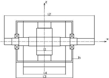
A three-phase asynchronous machine is considered in this paper. Based on the modal experiment results, the asynchronous machine vibrates rigidly within 450 Hz. Therefore, the stator system is simplified as a rigid cylindrical shell, and the rotor shaft system is simplified as a rigid step shaft. The frame is simplified as a beam considering the small influence on the overall stiffness. The mechanical model of torsional vibration on stator and rotor coupling is shown in Fig. 1.
Fig. 1Mechanical model of torsional vibration
For torsional modes, the kinetic energy and potential energy of the system can be expressed as:
where and are equivalent moments of inertia, and are relative angles of the rotor shaft and stator system, respectively. and are the magnetic permeabilities, respectively. is equivalent composite stiffness of rolling bearing and rotor shafting, and . is equivalent stiffness of stator frame torsion around -axis. and can be determined as:
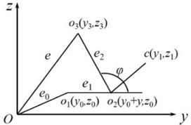
where, is the distance between two rolling bearings. Through the experiments, the stator and rotor system will produce torsional vibration around the -axis in low frequency vibration region. At this time, there is no obvious deformation of the stator system and rotor shaft system, and both of them show the rigid modes. Therefore, the eccentric diagram of torsional vibration is shown in Fig. 2, where is the center of the stator circle, is the outer circle center of rotor journal, is the center of the outer circle of the journal after deformation of the shaft or bearing, is the geometric center of the rotor outer circle. And is the mass center of the rotor, is static eccentricity, is rotor vibration eccentricity, is rotational eccentricity. Then, the vibration displacement of torsional vibration mode can be expressed as:
where, is relative torsion angle. When the motor is started with variable frequency speed regulation, the air gap energy between stator and rotor can be derived, and the terms higher than second order are neglected as follows:
Here, the linear part of magnetic field energy can be obtained as:
And the nonlinear part of magnetic field energy can be obtained as:
The linear part of magnetic field energy, kinetic energy and potential energy in Eq. (1) constitute the Lagrange function (), and substituting it to the Lagrange-Maxwell equation which can be used to solve the natural vibration equations as:
where and . One can obtain natural frequencies ( and ) and mode shapes from Eq. (7) based on the motor parameters. The natural frequencies calculated by this method have a good accuracy in the low frequency region. Compared with the experimental value, the error is no more than 15 %, especially the first order natural frequency, the error is less than 10 %. At the same time, the bearing stiffness and electromagnetic stiffness will also affect the calculation accuracy of natural frequencies, which is not considered in this paper.
Fig. 2Eccentricity of torsional vibration
3. The solution of triple resonances involving two frequencies
The nonlinear part of energy is used to solve the triple resonance of nonlinear vibration. The nonlinear part of kinetic energy and potential energy in this problem is zero, only the air gap energy is left. Variation calculation for the nonlinear part of the energy is taken, and its mean value can be derived as:
The solution of vibration is assumed to be:
Considering triple resonance frequency relation as:
Introducing three acyclic coordinates as:
Substituting Eqs. (9-11) into Eq. (8), the nonlinear vibration equations of stator and rotor coupling rigid body model in torsional vibration modes can be deduced as:
For steady-state solution, by canceling the time derivatives (), one can obtain the higher order equations of and as:
4. Numerical simulation and discussion
Take a three-phase asynchronous machine as an example to discuss the influence of tuning parameters and electromagnetic parameters on resonance characteristics.
Fig. 3 shows the triple resonance curves of torsional vibration mode excited by various electromagnetic force components. The solid line represents the amplitude () of the rotor shafting which is a typical bimodal curve, and the dotted line represents the amplitude () of the stator system. The vibration of rotor shaft system is stronger than stator system. When 0, the curve is symmetric M-type. There is energy conversion between different modes. Fig. 3(b) and (c) illustrate different forms of transformation when both of and are positive or negative at the same time. The resonance region is wider than that excited by a single frequency.
Fig. 4(a) shows the resonance curves of different damping coefficients. It can be seen that the smaller the damping is, the narrower the resonance region is. However, with the amplitude of rotor vibration increasing, it is easy to enter into the instability region. The higher the peak value of the rotor vibration curve is, the more prone the stator and rotor to rub and produce noise. Therefore, the damping of the system should be strictly controlled. The electromagnetic force is proportional to the base value of magnetic flux-density. Fig. 4(b) shows the electromagnetic force is much more stronger when the base value of magnetic flux-density is higher. The amplitude of stator system increases significantly, which exceeds the amplitude of the rotor shaft system. This phenomenon illustrates that the electromagnetic force has a significant effect on the vibration amplitude of the stator system.
Fig. 3The frequency-response curves with different tuning parameters
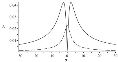
a), 0
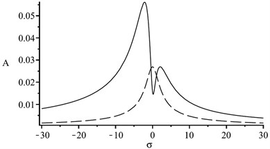
b), 0
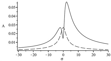
c), 0
Fig. 4The frequency-response curves
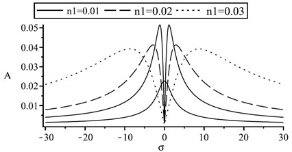
a) Influence of damping coefficient
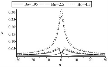
b) Influence of magnetic flux-density
5. Conclusions
According to motor vibration experiment, the motor generates rigid body vibration within a certain frequency range. Introducing the energy method, the Lagrange-Maxwell equation is used to solve the natural frequencies and mode shapes with the linear part of magnetic field energy. The nonlinear part as a disturbance energy to deduce the nonlinear vibration equations of stator and rotor coupling rigid body model in torsional vibration modes. Finally, the characteristics of triple resonance involved two natural frequencies are analyzed.
The simulation results illustrate that the tuning parameters, damping coefficient and magnetic flux-density have significant influence on vibration characteristics. The rotor shafting amplitude curve is a symmetric M-type bimodal curve. Thus, the stator system is very sensitive to electromagnetic excitation. When there is internal resonance in the system, multiple resonance is easily excited. And there is energy conversion between the modes. This work provides theoretical reference for the optimization of the whole structure and the design of reliability operation of the stator and rotor coupling system.
References
-
Yang Z., Li W., Qiu J., et al. Lagrange-Maxwell equation and magnetic saturation parametric resonance of generator set. Applied Mathematics and Mechanics, Vol. 28, Issue 11, 2007, p. 1545-1553.
-
Inayat-Hussain J. Nonlinear dynamics of a magnetically supported rigid rotor in auxiliary bearings. Mechanism and Machine Theory, Vol. 45, Issue 11, 2010, p. 1651-1667.
-
Li B., Zhang Q. The combined internal and principal parametric resonances on continuum stator system of asynchronous machine. Shock and Vibration, Vol. 2014, 2014, p. 835104.
-
Eftekhari M., Rahmatabadi A., Mazidi A. Nonlinear vibration of in-extensional rotating shaft under electromagnetic load. Mechanism and Machine Theory, Vol. 121, 2018, p. 42-58.
-
Chai F., Li Y., Pei Y., et al. Analysis of radial vibration caused by magnetic force and torque pulsation in interior permanent magnet synchronous motors considering air-gap deformations. IEEE Transactions on Industrial Electronics, Vol. 66, Issue 9, 2019, p. 6703-6714.
-
Chen L., Wang J., Han Q., et al. Nonlinear dynamic modeling of a simple flexible rotor system subjected to time-variable base motions. Journal of Sound and Vibration, Vol. 404, 2017, p. 58-83.
-
McCloskey A., Arrasate X., Hernández X., et al. Analytical calculation of vibrations of electromagnetic origin in electrical machines. Mechanical Systems and Signal Processing, Vol. 98, 2018, p. 557-569.
-
Yang X., Zhang W. Nonlinear dynamics of axially moving beam with coupled longitudinal-transversal vibrations. Nonlinear Dynamics, Vol. 78, Issue 4, 2014, p. 2547-2556.
About this article

This research was funded by Scientific Research Program of Tianjin Education Committee (Grant No. 2017KJ113).
