Abstract
We study the two-dimensional turbulent transonic flow past a symmetric profile with a blunt base and flat sides. The numerical simulation is based on the unsteady Reynolds-averaged Navier-Stokes equations. The obtained solutions reveal both symmetric and asymmetric oscillating flows past the profile at zero angle of attack. An occurrence of the symmetric or asymmetric flow regime depends on the time history of boundary conditions. A jet injection into the wake does not eliminate the flow non-uniqueness, though attenuates flow oscillations.
1. Introduction
A thermal protection of blades is an important point in turbine engineering. An up-to-date design of blades usually incorporates a coolant flow injection through an orifice in the trailing edge of blade. The injection and flow behavior in the base region were investigated experimentally and numerically in a number of works [1-3]. The paper [3], e.g., focused on the development of oscillations in the wake of a flat-sided profile with a blunt base. The obtained time-averaged flows were symmetric about the airfoil’s chord. Meanwhile, in 2000s numerical studies showed that flat-sided airfoils admit asymmetric flows at zero angle of attack apart from symmetric ones [4] due to instability of a shock wave interaction with the flow acceleration region developed at the rear of airfoil.
In the present paper, we consider transonic flow over a simple flat-sided profile similar to the one examined in [3] with an emphasis on the asymmetric flow regimes. An effect of a jet injection on the lift coefficient oscillations is discussed.
2. Problem formulation and numerical method
The symmetric profile No. 1 under consideration is constituted by:
(a) two parallel segments , ;
(b) the nose , ;
(c) the rear at 0 0.3; −0.08/3 0.08/3 at 0.8,
where are non-dimensional Cartesian coordinates. Profile No. 1 is actually a 20 percent truncation of a double wedge discussed in [5]. The fully turbulent flow over profile No. 1 is governed by the unsteady Reynolds-averaged Navier-Stokes equations (URANS) with respect to the static temperature , density , and velocity components , , where is time.
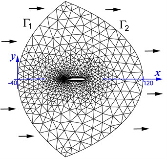
A lens-type outer boundary of the computational domain is constituted by arcs and , which extend from −100 to 100 in the -direction and from −40 to 120 in the -direction, see Fig. 1. On the inflow part we prescribe the temperature 250 K, angle of attack 0, free-stream Mach number 1, and turbulence level of 1 %. The air is treated as a perfect gas whose heat capacity ratio is 1.4 and the specific heat at constant pressure is 1004.4 J/(kg K).
On , we set the static pressure 3×10⁵ N/m2, which is related to and by the equation of state , . On profile No. 1, we impose the no-slip condition and zero heat flux. Initial conditions are either parameters of the free stream or a nonuniform flow obtained for other values of . In Section 4, we will formulate an extra condition that simulates a jet injection through an orifice at 0.8.
The URANS equations were solved with ANSYS-18.2 CFX finite-volume solver [6] using the SST - turbulence model [7]. A computational mesh was constituted by quadrilaterals in 40 layers on profile No. 1 and by triangles in the rest of computational domain. The total number of mesh cells was 467,904, and the dimensionless thickness of the first mesh layer on profile No. 1 was less than 1. The cells were clustered near the profile for an accurate resolution of the boundary layer and shocks. The time step of 10−5 s ensured the root-mean-square Courant-Friedrichs-Lewy number smaller than 2.
Fig. 1Sketch of the computational mesh
3. Symmetric and asymmetric flows at zero angle of attack
First, we used the uniform free stream for initialization of time-dependent solutions and flow computation in the bands:
In band (1) numerical simulations demonstrated a development of an oscillating symmetric flow with two local supersonic region (in which 1) on both sides of profile. The oscillations are caused by instability of the boundary layer separation at the rear and instability of the vortex pattern in the wake.
In band (2) the solutions showed a development of an oscillating symmetric flow in which there is a large local supersonic region terminated by a shock wave on each side of profile.
In band (3) the numerical simulations revealed that, due to instability of the symmetric flows, there is a transition to an asymmetric regime with either negative or positive -component of the aerodynamic force, i.e., lift , obtained by integration of flow pressure over the profile. To provide a transition, e.g., to the flow regime with positive lift, one can prescribe a perturbation 0.1° for the angle of attack on followed by a reset of to 0. For example, Fig. 2 shows instantaneous iso-Mach lines in the asymmetric flow with 0 obtained at 0.845.
The calculated asymmetric flow at 0.845 was then used for flow computations step-by-step at smaller and larger . This scenario made it possible to determine the bifurcation band (4):
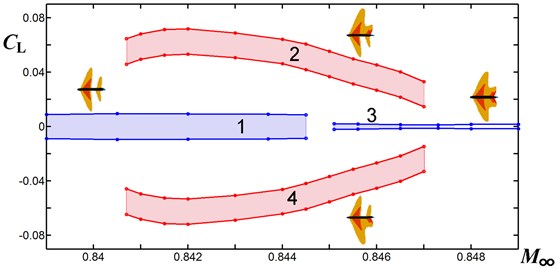
in which the asymmetric flows (with positive or negative lift ) are stable with respect to small perturbations. We notice that band (4) is 1.4 times longer than a bifurcation band for the full (non-truncated) double wedge [5]. Margins of the oscillating lift coefficient ×1 [m]) are displayed in Fig. 3, where sketches next to regions 1-4 point out the number and locations of supersonic regions in the flow. The frequency of lift oscillations is approximately 2100 Hz in regions 1, 2, 4, and it increases to 4000 Hz in region 3. The Reynolds number based on the length of profile 0.4 m is 1.1×10⁷.
Fig. 2Instantaneous iso-Mach lines in the flow with L> 0 over profile No. 1 at M∞= 0.845
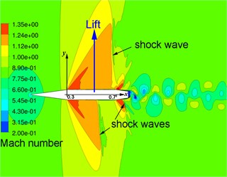
Fig. 3Margins of lift coefficient oscillations over profile No. 1 versus M∞ at zero angle of attack: regions 1 and 3 – symmetric flows, regions 2 and 4 – asymmetric ones
4. Flow control by a jet injection
To control flow oscillations, we set a jet emanating from the orifice −9.2×10-39.2×10-3, 0.8 in the base of profile No. 1. In the orifice, we prescribe the static pressure along with static temperature 250 K. Computations showed a high sensitivity of the amplitude of lift coefficient oscillations to the ratio . This is explained by small velocities of the flow in the base region and its intricate structure, which is sensitive to weak perturbations.
For example, in the asymmetric flow at 0.830, the increase in from 0.73 to 0.933 yields a four times decrease in the amplitude of oscillations, see region 2 in Fig. 4. Though this pressure rise produces very small Mach numbers in the jet, this attenuates considerably flow oscillations in the wake. The attenuated oscillations in the wake result in a damping effect on the oscillations of via the boundary layer and subsonic region over the rear of profile.
Further increase in from 0.933 to 1.0 leads to the full damping of oscillations, see Figs. 4, 5, though it does not change the mean value of . We notice that an increase of from 0.950 to 0.967 triggers a development of low frequency oscillations, on which a higher frequency is superposed, see Fig. 6.
In the symmetric flow regime, the jet injection also produces a damping effect on the oscillations, see region 1 in Fig. 4. In addition, the rise of is accompanied by a reduction of the spacing between local supersonic regions on both sides of profile No. 1. This eventually triggers a transition from the symmetric regime to an asymmetric one at 0.935.
At the larger free-stream Mach number 0.8455, computations showed a similar effect of jet injection on the asymmetric and symmetric flows.
Fig. 4Margins of the lift coefficient oscillations at M∞= 0.843 versus the relative jet pressure pjet/p∞: region 1 – symmetric flow, region 2 – asymmetric flow
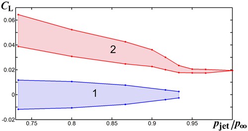
Fig. 5Static pressure contours and velocity vectors in the near wake of asymmetric flow at M∞= 0.843 with jet injection, pjet/p∞= 1
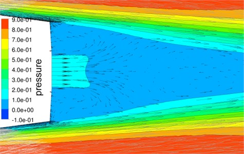
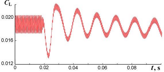
Fig. 6A change of lift coefficient oscillations in time caused by the change of pjet/p∞ from 0.950 to 0.967 at t= 0.018 s
5. Conclusions
The turbulent transonic flow over profile No. 1 exhibits oscillations and non-uniqueness of flow regimes at zero angle of attack and free-stream Mach numbers (4). Oscillations of the lift coefficient are very sensitive to the subsonic jet emanating from the blunt trailing edge/base. The numerical simulation showed that, at 0.843 and 0.8455, the jet injection attenuates the oscillations, though does not eliminate the flow non-uniqueness.
References
-
Raffel M., Kost F. Investigation of aerodynamic effects of coolant ejection at the trailing edge of a turbine blade model by PIV and pressure measurements. Experiments in Fluids, Vol. 24, 1998, p. 447-461.
-
Martinez-Cava A., Wang Y., Vicente J., Valero E. Pressure bifurcation phenomenon on supersonic blowing trailing edges. American Institute of Aeronautics and Astronautics Journal, Vol. 57, 2019, p. 153-164.
-
Martinez-Cava A., Valero E., Vicente J., Paniagua G., Soedel W. Coanda flow characterization on base bleed configurations using global stability analysis. American Institute of Aeronautics and Astronautics, 2019, https://doi.org/10.2514/6.2019-0881.
-
Kuzmin A. Non-unique transonic flows over airfoils. Computers and Fluids, Vol. 63, 2012, p. 1-8.
-
Kuzmin A. Transonic flow bifurcations over a double wedge. Journal of Physics: Conference Series, Vol. 1697, 2020, p. 012207.
-
ANSYS Fluids – Computational Fluid Dynamics, 2020, https://www.ansys.com/products/fluids.
-
Menter F. R. Review of the shear-stress transport turbulence model experience from an industrial perspective. International Journal of Computational Fluid Dynamics, Vol. 23, 2009, p. 305-316.
About this article

This research was performed using computational resources provided by the Computational Center of St. Petersburg State University (http://cc.spbu.ru). The work was partially supported by the Russian Foundation for Basic Research under grant no. 19-01-00242.
