Abstract
In this work a parameter optimization method is applied to determine the best values of damping and stiffness properties which will minimize the magnitude of the vertical acceleration of the ambulance stretcher. Thus, an 8-DOF vehicle dynamic model was developed to be used for the parameter optimization method. Subsequently, the results obtained by the model were compared to a full vehicle multi-body model of Carsim software. Damping and stiffness properties, which are obtained by a parameter optimization method, contribute to reducing the magnitude of the vertical acceleration of the ambulance stretcher. The approach developed in this study provides sources for designing a mechanism to reduce the vertical acceleration to which the patient is exposed during transportation in an ambulance.
Highlights
- Analysis of the effects of global stiffness and damping parameters of a system to attenuate vibrations on patients transported by an ambulance
- An 8-DOF Vehicle Model to analyze the contribution of a vibration attenuation system for an ambulance stretcher
- Adherence between the results calculated by the 8-DOF Vehicle Model and the ones obtained from Carsim software
- Through a parameter otimization, the magnitude of the ambulance stretcher vertical acceleration is minimized
1. Introduction
When someone is affected by a sudden illness or by serious injuries due to an accident, he/she must be transported quickly and safely in order to have appropriate medical care. Vehicles used in these cases, however, are relatively heavier and less comfortable than passenger cars. In Brazil, ambulances are usually customized or adapted from cargo transport vehicles, such as trucks or vans. Patients transported by these vehicles are exposed to severe accelerations, particularly due to braking, in curves, and by driving over obstacles or uneven pavements [1]. The vibration produced when an ambulance drives over an uneven surface can affect the vital functions of the human body (cardiovascular system, skeleton, central nervous system, respiratory system), being harmful to the already delicate clinical condition of the patient [2].
Patients transported in recumbent position are more sensitive to vertical vibrations when compared to a passenger in a standing or seated position [3]. In addition, vibration of the human body is most uncomfortable for sick or injured patients.
Although a few studies have been carried out regarding the analysis of the influence of the stretcher stiffness on ride comfort for patients transported by ambulances [3-4], some works have shown that the use of vibration attenuation system, such as a cabin suspension, can improve ride comfort [5-7].
Models such as quarter car, half car and full vehicle are commonly adopted to analyze ride comfort. Wei et al. [8] and Baumal et al. [9] applied a half-vehicle model with 5 DOF to design an optimal controller for an active suspension system. The seat vertical acceleration was the main objective chosen to be minimized. Wang et al applied an optimal fuzzy control method which the control rules are defined by the optimal algorithm and utilized to a 4 DOF car model [10]. Xuan et al. 2018 analyzed the suspension parameters of a 10 DOF three-dimensional model of bus based on the weighted root-mean-square acceleration responses [11].
In view of the above, the goal of this study is to obtain the damping and stiffness coefficients of a system to attenuate the vibration effects on patients transported by an ambulance. The results obtained can be useful for designing of a mechanism which is capable of reducing the vertical acceleration that the patient is exposed during the ambulance transportation.
2. Methodology
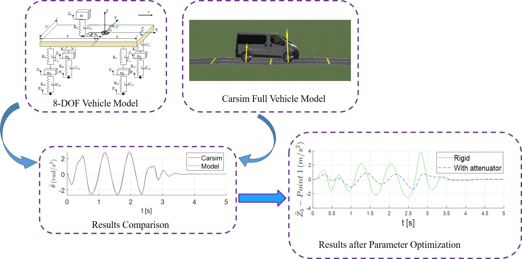
First, a vibration model is established. Then, the results obtained by the 8-DOF model are compared to a full vehicle multi-body model of Carsim software. Finally, a parameter optimization method is applied to determine the best values of the system damping and stiffness properties which minimize the magnitude of the ambulance stretcher vertical acceleration.
2.1. Vibration model
Fig. 1(a) shows the 8-DOF of the dynamic model of a vehicle, which are the vertical displacements of the stretcher and of the vehicle mass center, roll and pitch angles of sprung mass, and the vertical displacement of each wheel. The independent wheel suspension, the tire and the vibration attenuation system under the stretcher are modeled by linear springs with dampers. In the dynamic analysis the vehicle behavior was simulated driving over a sinusoidal road profile with a speed of 30 km/h. A sinusoidal shape of the road profile consists of three successive bumps of height equal to 0.1 meters and total length of 19.5 m [9]. This road input introduces bounce and pitch motion of the vehicle sprung mass simultaneously, as illustrated in Fig. 1(c).
Fig. 1a) 8-DOF vehicle dynamic model; b) locations of points 1 and 2 and vehicle’s mass center G [5]; c) sinusoidal road profile
![a) 8-DOF vehicle dynamic model; b) locations of points 1 and 2 and vehicle’s mass center G [5]; c) sinusoidal road profile](https://static-01.extrica.com/articles/21994/21994-img1.jpg)
a)
![a) 8-DOF vehicle dynamic model; b) locations of points 1 and 2 and vehicle’s mass center G [5]; c) sinusoidal road profile](https://static-01.extrica.com/articles/21994/21994-img2.jpg)
b)
![a) 8-DOF vehicle dynamic model; b) locations of points 1 and 2 and vehicle’s mass center G [5]; c) sinusoidal road profile](https://static-01.extrica.com/articles/21994/21994-img3.jpg)
c)
The equations of motion for the system presented in Fig. 1 are derived according to the Lagrangian formalism:
In this equation, is the Lagrangian of the system, and each represents a generalized coordinate of the system. The corresponding expressions for the kinetic () and potential () energies, and for the Rayleigh dissipation function () are shown in Appendix.
The differential equations of motion are represented in matrix form, as follows:
where is the column-vector of generalized coordinates.
The Dormand-Prince Runge-Kutta method (DOPRI54) is applied for numerical integration. The initial position (starting point) of all variables and their first time derivative are zero.
The natural frequencies of the system were calculated by solving the associated eigenvalue problem:
where stand for the natural frequencies of the system.
2.2. Vehicle parameters
The ambulance parameters applied to the simulations (Table 1) are compatible with Mercedes-Benz's Sprinter 415 CDI 7.5 m3 vehicle adapted to the ICU model, widely used for patients transport in Brazil, while Fig. 1(b) illustrates the corresponding ambulance parameters.
Table 1Ambulance parameters applied in simulations
Parameters | Values | Parameters | Values |
Sprung mass [kg] | 2600 | Front suspension stiffness [N/m] | 198×103 |
Roll inertia [kgm2] | 658 | Rear suspension stiffness [N/m] | 130×103 |
Pitch inertia [kgm2] | 4174 | Front suspension damping [Ns/m] | 12500 |
Wheel centers [mm] (front and rear) | 1550 | Rear suspension damping [Ns/m] | 12500 |
Front unsprung mass [kg] (both sides) | 150 | Tire stiffness [N/m] (front and rear) | 250×103 |
Rear unsprung mass [kg] (both sides) | 100 | Tire damping [Ns/m] (front and rear) | null |
2.3. Parameter optimization and analysis
In order to achieve a good performance in terms of the ride comfort of the passenger, engineers usually point out improvements in the design of vehicle suspension. However, in Brazil, ambulances usually are adapted from cargo transport vehicles which do not have a customizable suspension. Because of that, ride comfort may not be suitable for patients, and it could aggravate their clinical condition during their transportation.
In view of the above, the authors of this article have been developing a system whose purpose is to attenuate vibrations on ambulance stretchers. In this study, a parameter optimization method is applied to determine the damping and stiffness coefficients of this system that could minimize the vertical acceleration of the stretcher. According to Baumal [9], ride comfort is improved when the magnitude of vertical acceleration is reduced. So, the objective function of the optimization problem is designed to minimize the vertical acceleration experienced by the patient. The point chosen to calculate the acceleration, denoted as point “2” in Fig. 1(b), represents the abdominal region, defined based on the anthropometric dimensions of a medium stature person [12].
As constraints to the optimization problem, the maximum allowable jerk experienced by the patient ( 18 m/s3) is chosen in accordance with [13], and the workspace of the vibration attenuation system is limited according to the following inequality:
In view of the above, the optimization problem was formulated as follows:
– Minimize .
– Subject to
This constrained optimization problem was solved by applying the square quadratic programming (SQP), implemented in MATLAB software, using the built-in fmincon function.
3. Results and discussion
3.1. Comparison between the results obtained by the model and Carsim software
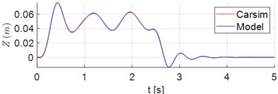
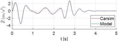
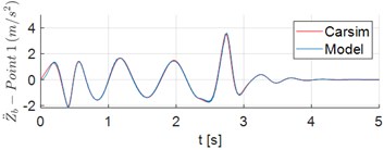
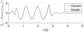
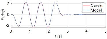
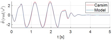
Results of the vehicle dynamic simulations demonstrate responses to displacements and acceleration of the ambulance which rides the Sinusoidal Road Profile described in Section 2.1. First, the results obtained by the 8-DOF model are compared to the corresponding ones obtained from a simulation in Carsim adopting the same parameters, inputs and initial conditions. Fig. 2(a) and 2(b) show the displacement of the mass center of the vehicle (), and the vertical acceleration of , respectively. The time series of vertical acceleration of points 1 and 2 are illustrated in Fig. 2(c) and 2(d). In this simulation scenario the accelerations of these points of the stretcher were computed in the absence of a patient. The corresponding pitch angle and pitch acceleration of sprung mass, in turn, are shown in Fig. 2(e) and 2(f). The results in Fig. 2 clearly show the adherence between the results obtained from the proposed model and the ones from Carsim software.
Fig. 2Time series of displacements and accelerations: a) displacement of vehicle center of mass G; b) vertical acceleration of vehicle center of mass G; c)-d) vertical acceleration of points 1 and 2, respectively; e) pitch angle of sprung mass; f) pitch acceleration of sprung mass
a)
b)
c)
d)
e)
f)
3.2. Parametric optimization analysis
As previously mentioned, the goal of this study is to determine the damping and stiffness coefficients of a vibration attenuation system to be designed for mounting a stretcher in an ambulance, which may be capable to minimize the magnitude of the corresponding vertical acceleration of this stretcher.
Table 2 lists the results obtained from the choice of five independent starting points for the parametric optimization algorithm. It can be observed that the minimum vertical acceleration of stretcher, measured in point 2 see Fig. 1(b), was achieved with the parameters = 2000 N/m and = 349.7 Ns/m. Additionally, all the constraints of the problem are satisfied. In Table 2, represents 1st natural frequency, associated to movement.
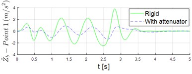
Fig. 3 shows the time series of accelerations of points 1 and 2 when the ambulance rides the Sinusoidal Road Profile described in Section 2.1. The patient plus stretcher mass adopted in the simulation is equal to 120 kg.
Table 2Results from parametric optimization
Parameters | Starting points | ||||
[N/m] | 3000 | 5000 | 10000 | 13000 | 16000 |
[Ns/m] | 300 | 100 | 300 | 200 | 350 |
Results | |||||
[N/m] | 2000 | 2000 | 2000 | 2000 | 2000 |
[Ns/m] | 354.8 | 349.7 | 349.7 | 349.7 | 349.7 |
Peak of [mm] | 79.5176 | 80 | 80 | 80 | 80 |
Peak of [m/s2] | 2.0669 | 2.0617 | 2.0617 | 2.0617 | 2.0617 |
Peak of [m/s3] | 16.7917 | 16.6288 | 16.6288 | 16.6288 | 16.6288 |
[Hz] | 0.6471 | 0.6471 | 0.6471 | 0.6471 | 0.6471 |
The vibration attenuation system is capable of significantly reducing the vertical acceleration in both the head (point 1) and stomach region (point 2) of patient as shown in Fig. 3. The peaks of acceleration at Points 1 and 2 were reduced in 63.1 % and 58.4 %, respectively. In addition, the peaks of stretcher jerk () at points 1 and 2 points decreased from 35.08 m/s3 to 13.87 m/s3 and from 40.94 m/s3 to 16.63 m/s3, respectively.
Fig. 3Time series of vertical acceleration stretcher when it is rigidly mounted vs. when the attenuation system is used: a) point 1; b) point 2
a)
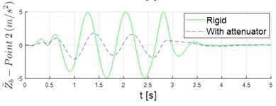
b)
4. Conclusions
This study analyzed the effects of the global stiffness and damping parameters of a system to be designed in order to attenuate vibrations on patients transported by an ambulance. The preliminary analysis herein introduced is based on the use of the 8-DOF vehicle model, subjected to vibrations caused by a particular road surface profile. A comparison with a simulation performed using the Carsim software, allows to verify that the proposed 8-DOF model is adequate for representing the dynamic response for the vehicle in the proposed scenario.
After that, a parameter optimization problem was solved to determine the optimal values of damping and stiffness of the attenuation system, that minimize the magnitude of the vertical acceleration of the ambulance stretcher when compared to a scenario in which the stretcher is rigidly mounted in the ambulance. It is also noticed that the associated jerk is significantly reduced when the attenuator is adopted.
Therefore, the preliminary analyses presented in this study shall be useful for designing an actual mechanism for mounting the stretcher in the ambulance so that the vertical acceleration that the patient is exposed during the transportation could be significantly attenuated.
References
-
Joshi O. P., Jadhav T. A., Pawar P. R., Saraf M. R. Investigating effect of road roughness and vehicle speed on the dynamic response of the seven degrees-of-freedom vehicle model by using artificial road profile. International Journal of Current Engineering and Technology, Vol. 5, 2015, p. 2596-2602.
-
Menon V. A. Product Development Approach for a Stabilized Ambulance Stretcher. Master’s Thesis, Instituto Superior de Engenharia do Porto, Porto, Portugal, 2018.
-
Raemaekers A. Active Vibration Isolator Design for Ambulance Patients. Master’s Thesis, Eindhoven University of Technology, Eindhoven, Holland, 2009.
-
Marques L., Malvezzi F., Stavropoulos K. D. Analysis of movements and degrees of freedom required for a vibration attenuation system on ambulance stretchers. Vibroengineering Procedia, Vol. 32, 2020, p. 81-86.
-
Lyashenko M. V., Pobedin A. V., Potapov P. V. Analysis of possible dynamic vibration dampers Uses in tractor cabins suspensions. Procedia Engineering, Vol. 150, 2016, p. 1245-1251.
-
Sharma S. K., Pare V., Chouksey M., Rawal B. R. Numerical studies using full car model for combined primary and cabin suspension. Procedia Technology, Vol. 23, 2016, p. 171-178.
-
Sim K., Lee H., Yoon J. W., Choi C., Hwang S.-H. Effectiveness evaluation of hydro-pneumatic and semi-active cab suspension for the improvement of ride comfort of agricultural tractors. Journal of Terramechanics, Vol. 69, 2017, p. 23-32.
-
Wei C., Zhang K., Cai Y., et al. A new method of static output-feedback H∞ controller design for 5 DOF vehicle active suspension system. Journal of the Brazilian Society of Mechanical Sciences and Engineering, Vol. 40, 2018, p. 132.
-
Baumal A. E., Mcphee J. J., Calamai P. H. Application of genetic algorithms to the design optimization of an active vehicle suspension system. Computer Methods in Applied Mechanics and Engineering, Vol. 163, Issues 1-4, 1998, p. 87-94.
-
Wang W., Song Y., Chen J., et al. A novel optimal fuzzy integrated control method of active suspension system. Journal of the Brazilian Society of Mechanical Sciences and Engineering, Vol. 40, 2018, p. 29.
-
Xuan L. L., Van Q. L., Van C. B. Study on the influence of bus suspension parameters on ride comfort. Vibroengineering Procedia, Vol. 21, 2018, p. 77-82.
-
Pheasant S., Haslegrave C. M. Bodyspace: Anthropometry, Ergonomics and the Design of Work. 3rd Edition, Boca Raton, CRC Press, 2006.
-
Shirahatti A., Prasad P. S. S., Panzade P., Kulkarni M. M. Optimal design of passenger car suspension for ride and road holding. Journal of the Brazilian Society of Mechanical Sciences and Engineering, Vol. 30, Issue 1, 2008, https://doi.org/10.1590/S1678-58782008000100010.
Cited by
About this article

The authors acknowledge grant #2018/12087-7 – São Paulo Research Foundation (FAPESP), and Maua Institute of Technology for the support.
