Abstract
This work deals with an analysis of the acceleration level to which a patient is exposed during ambulance transportation. A dynamic analysis of ambulance movements has been approached considering some different operating conditions of the vehicle, such as braking, driving over speed bumps and on uneven pavements. The purpose of this study is providing sources for development of a system reducing vibration effects on the body when a patient is transported by ambulance.
Highlights
- The vehicle dynamic analysis simulated the behavior of the ambulance during sudden braking, and driving over different types of road unevenness
- A full vehicle multi-body model with 16 degrees of freedom and 34 bodies was employed in the simulations
- The results obtained provide useful inputs for the development of systems for reducing the vibration effects on the patient’s body
1. Introduction
When a person is affected by sudden illness or has suffered more serious injuries in accident, he/she must be transported quickly and safely to a place for providing appropriate care. The vehicles used in these cases are relatively heavier and less comfortable than passenger cars. In Brazil, ambulances usually have been either customized or adapted from cargo transport vehicles, such as trucks or vans. As patients are carried in the back of the vehicle, they are exposed to accelerations during the transportation, either by braking, in curves, driving over obstacles or uneven pavements that directly influence the movements of the vehicle [1]. The vibration produced by uneven surface can affect the vital function of the human body (cardiovascular system, skeleton, central nervous system, respiratory system), and may aggravate still more the clinical condition of the patient [2]. In the case of patients who suffered heart attack, stroke, or have disabilities that cause chronic pain and discomfort (arthritis, multiple sclerosis, back pain), they require special care due to their increased sensitivity to vibrations generated during the transport, which may impact their health conditions [3].
The ISO 2631 standard describes how to evaluate human body exposure to vibration [4, 5]. Patients transported in the recumbent position are more sensitive to vertical vibrations when compared to standing or seated position [6]. In addition, vibration of the human body is most uncomfortable for sick or injured patients.
Road unevenness can be either discrete or even extended for the road which an ambulance goes through. Unevenness along the road may have either a sinusoidal or stochastic profile. The ISO 8608 standard classifies stochastic road roughness by power spectral density (PSD) for both paved and unpaved roads [7].
Regarding discrete unevenness, speed bumps are installed on the roads in order to control car speed and prevent traffic accidents [8]. The Watts Profile is a kind of speed bump widely used in works about ride comfort Fig. 1(a) [9]. In Brazil, Contran (National Traffic Council) is a government entity which determines implementation of a kind of speed bump similar to Watts Profile. However, in many streets there are speed-humps different to this pattern.
In the context mentioned above, this paper presents a dynamic analysis of an ambulance considering many operating conditions, such as braking, and driving on uneven pavement. As previous papers related to ride comfort usually do not focus on any particular kind of ambulance transport, the purpose of this study is to analyze movements and their respective accelerations as it can affect the comfort of patients transported by ambulance. The results obtained provide inputs for the development of a system for reducing the vibration effects on the patient body.
2. Method
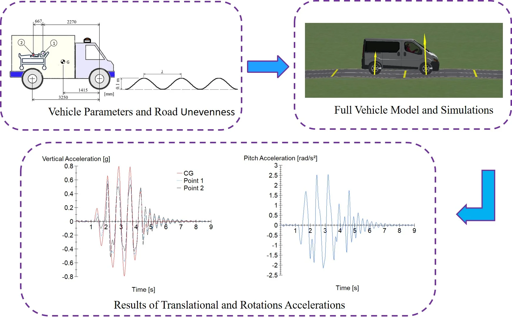
In order to evaluate the patient body exposure to vibration during ambulance transportation, the CarSim software has been applied. It employs a full vehicle multi-body model with 16 degrees of freedom and 34 bodies. The dumpers are nonlinear and the elastic kinematic effect of the suspension is also considered. The mathematical model of the tire is nonlinear too. The ambulance parameters applied to the simulations are compatible with Mercedes-Benz's Sprinter 415 CDI 7.5 m³ vehicle adapted to the intensive care unit (ICU) model, widely used for patients transport in Brazil. Table 1 lists the ambulance parameters applied in this study.
Table 1Ambulance parameters applied in simulations
Parameters | Values | Parameters | Values |
Sprung mass [kg] | 2600 | Front unsprung mass [kg] (both sides) | 150 |
Roll inertia [kg·m2] | 658 | Rear unsprung mass [kg] (both sides) | 150 |
Pitch inertia [kg·m2] | 4174 | Wheel centers [mm] (front and rear) | 1550 |
The dynamic analysis simulated the behavior of the vehicle during sudden braking, and driving over four distinct obstacles: Watts Profile, Sinusoidal Road Profile (with two different wavelengths) and Chassis Twist Road.
Sudden Braking: the purpose of this maneuver was to simulate a situation in which the driver needs to perform an unexpected braking, from the initial 50 km/h speed and 4 MPa maximum pressure in the master cylinder.
Watts Profile: it was employed in order to analyze the behavior of the vehicle running at 30 km/h speed through a standardized speed bump, as shown in Fig. 1(a) [9].
Chassis Twist Road: this maneuver, based on [10], simulated road excitations generated from the road profile unevenness with the 0.05 m height elevations, as illustrated in Fig. 1(b). The vehicle speed during the simulation was 45 km/h.
Sinusoidal Road Profile: two types of bumps were applied to simulate the road unevenness based on a sine profile. The maneuver namely indicates that the wavelength, in Fig. 2(a), is equal to the wheelbase of the simulated vehicle and the 2 indicates that the wavelength is twice the wheelbase. Both sinusoidal shapes of the road profile consist of three successive peaks of height equal to 0.1 meters. The vehicle speeds during the and 2 maneuvers were 15 km/h and 30 km/h, respectively. A sinusoidal shape of road profile is shown in Fig. 2(a).
Fig. 1a) Watts profile, b) chassis twist road
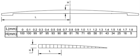
a)
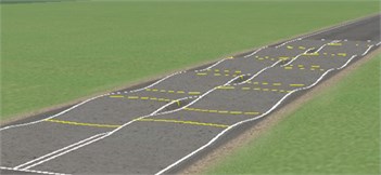
b)
It is important to emphasize that the vehicle speed during the maneuvers Watts Profile, Sinusoidal Road Profile, and Chassis Twist Road were chosen considering a typical speed of the ambulances when traveling through those bumps. Moreover, it was ensured the grip between tires and pavement to provide the expected control of the vehicle by the driver.
According to ISO 2631, the variables related to the patient discomfort are both translational and rotational accelerations. Thus, during the maneuvers, roll and pitch accelerations were calculated. Moreover, lateral and vertical accelerations were obtained for three different points: on the center of mass of the vehicle, on the head (point 1) and at the abdominal region of the patient (point 2). The locations of points 1 and 2 were defined based on the anthropometric dimensions of a medium stature person, obtained from the work of Pheasant and Haslegrave [11]. Fig. 2(b) shows the locations of the points 1 and 2, and the center of mass of the vehicle. The lateral coordinates of the points 1 and 2 are 40 mm.
Fig. 2a) Sinusoidal road profile; b) locations of points 1 and 2 and vehicle’s center of mass G
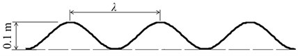
a)
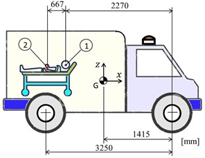
b)
3. Results and discussion
During the maneuver Watts Profile, vertical acceleration and pitch acceleration were analyzed (Fig. 3). The maximum and minimum values obtained at this maneuver are represented in Table 2. These results are in accordance with the ones presented by Raemaekers [6].
Fig. 3Watts profile maneuver: a) vertical acceleration, b) pitch acceleration
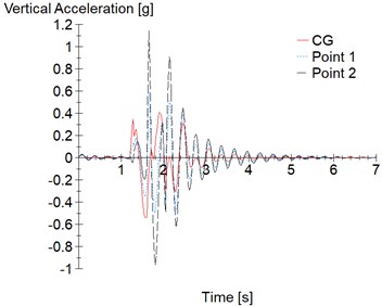
a)
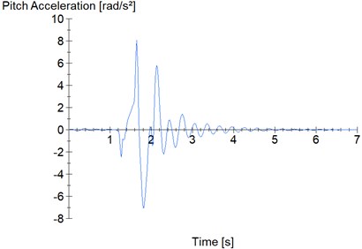
b)
Table 2Maximum and minimum values obtained during Watts Profile maneuver
Watts profile | Point | Maximum | Minimum |
Vertical acceleration [g] | Point 1 | 0.59 | –0.49 |
Point 2 | 1.14 | –0.96 | |
G | 0.41 | –0.54 | |
Pitch acceleration [rad/s²] | – | 8.08 | –7.07 |
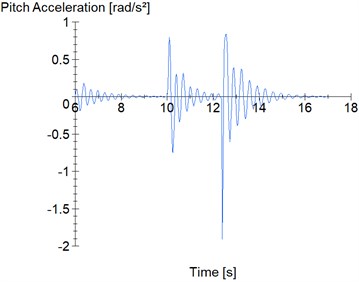
In the sudden braking maneuver, vertical, longitudinal and pitch accelerations were analyzed, as shown in Fig. 4. The maximum and minimum values obtained during this maneuver are shown in Table 3.
Fig. 4Sudden braking maneuver: a) vertical and lateral accelerations, b) pitch acceleration
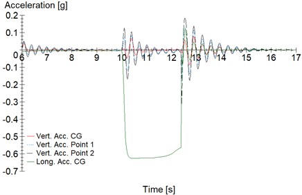
a)
b)
Table 3Maximum and minimum values obtained during sudden braking
Sudden braking | Point | Maximum | Minimum |
Vertical acceleration [g] | Point 1 | 0.13 | –0.18 |
Point 2 | 0.18 | –0.31 | |
G | 0.08 | –0.09 | |
Longitudinal acceleration [g] | G | 0.12 | –0.63 |
Pitch acceleration [rad/s²] | – | 0.84 | –1.91 |
When the ambulance drove through the Sinusoidal Road Profile, the vertical and pitch accelerations were analyzed. The results from maneuver are presented in Fig. 5 and, Fig. 6 shows the results of 2 maneuver. The maximum and minimum values obtained in these figures are listed in Tables 4 and 5, respectively.
Fig. 5Sinusoidal road profile – l maneuver: a) vertical acceleration; b) pitch acceleration
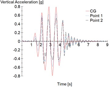
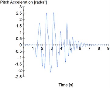
Table 4Maximum and minimum obtained during l maneuver
maneuver | Point | Maximum | Minimum |
Vertical acceleration [g] | Point 1 | 0.64 | –0.58 |
Point 2 | 0.54 | –0.51 | |
G | 0.80 | –0.79 | |
Pitch acceleration [rad/s²] | – | 2.55 | –2.15 |
Based on the results presented in Tables 5 and 6, it can be noted that the vehicle achieves the highest vertical acceleration during the maneuver , while during the maneuver 2 the pitch acceleration reaches the highest value.
During the Chassis Twist Road procedure vertical, lateral, pitch and roll accelerations were determined. Fig. 7 shows vertical, lateral and pitch accelerations. Results of roll acceleration is presented in Fig. 8. Table 6 lists the maximum and minimum values of the graphs presented in Fig. 7 and Fig. 8.
Fig. 6Sinusoidal road profile – 2l maneuver: a) vertical acceleration; b) pitch acceleration
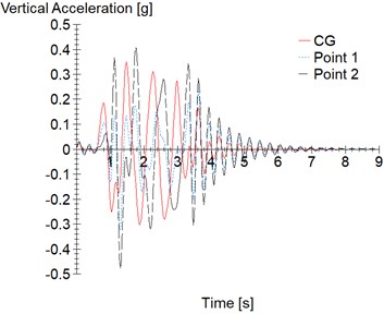
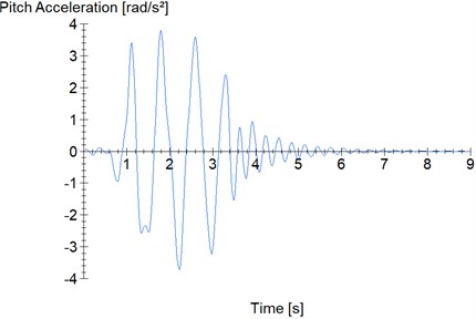
Table 5Maximum and minimum obtained during 2l maneuver
2 maneuver | Point | Maximum | Minimum |
Vertical acceleration [g] | Point 1 | 0.23 | –0.32 |
Point 2 | 0.40 | –0.48 | |
G | 0.35 | –0.30 | |
Pitch Acceleration [rad/s²] | – | 3.79 | –3.73 |
Fig. 7Chassis twist road procedure: a) vertical and lateral accelerations; b) pitch acceleration
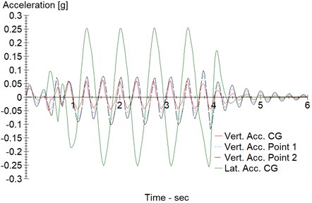
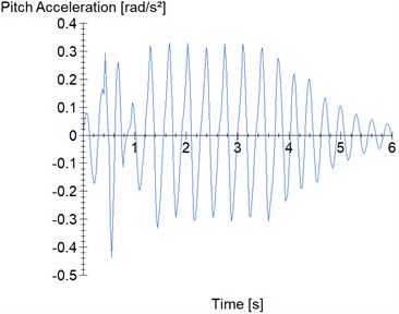
Fig. 8Roll angular acceleration
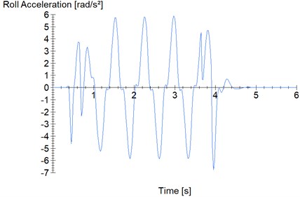
Table 6Maximum and minimum values obtained during Chassis Twist Road procedure
Chassis twist road | Point | Maximum | Minimum |
Vertical acceleration [g] | Point 1 | 0.08 | –0.10 |
Point 2 | 0.10 | –0.12 | |
G | 0.06 | –0.05 | |
Lateral acceleration [g] | G | 0.26 | –0.26 |
Pitch acceleration [rad/s²] | – | 0.33 | –0.43 |
Roll acceleration [rad/s²] | – | 5.90 | –6.76 |
4. Conclusions
This work presents how the acceleration affects a patient transported by ambulance. Translational acceleration was calculated on body regions such as the head and abdomen of the patient considering the vehicle executing five different maneuvers. Moreover, roll and pitch accelerations were taken into account too. According to previous works, the acceleration results obtained here may be harmful to the physical integrity of patients transported in the ambulance, which indicates the need to reduce vibrations in the ambulance stretcher. Vibration effects on the patient body could be reduced either by an active suspension system assembled between all wheels and the body of the ambulance or by a mechanism installed under the stretcher. The next step of this work may be a synthesis of a mechanism for reducing vibrations effects in both translational and rotational movements of the ambulance stretcher.
References
-
Joshi O. P., Jadhav T. A., Pawar P. R., Saraf M. R. Investigating effect of road roughness and vehicle speed on the dynamic response of the seven degrees-of-freedom vehicle model by using artificial road profile. International Journal of Current Engineering and Technology, Vol. 5, 2015, p. 2596-2602.
-
Menon V. A. Product Development Approach for a Stabilized Ambulance Stretcher. Master’s Thesis, Instituto Superior de Engenharia do Porto, Porto, Portugal, 2018.
-
Kennedy J., Oakley C., Sumon S., Parry I., Wilkinson E., Brown J. Impact of Road Humps on Vehicles and Their Occupants. Prepared for Charging and Local Transport Division, TRL Report TRL614, 2004.
-
ISO 2631-1, Mechanical Vibration and Shock – Evaluation of Human Exposure to Whole-Body Vibration. International Organization for Standardization, Switzerland, 1997.
-
Eriksson J., Svensson L. Tuning for Ride Quality in Autonomous Vehicle. Master’s Thesis, Uppsala University, Uppsala, Sweden, 2015.
-
Raemaekers A. Active Vibration Isolator Design for Ambulance Patients. Master’s Thesis, Eindhoven University of Technology, Eindhoven, Holland, 2009.
-
ISO 8608, Mechanical Vibration-Road Surface Profiles-Reporting of Measured Data. International Organization for Standardization, Switzerland, 1995.
-
Garcia-Pozuelo D., Gauchia A., Olmeda E., Diaz V. Bump modeling and vehicle vertical dynamics prediction. Advances in Mechanical Engineering, Vol. 6, 2014, https://doi.org/10.1155/2014/736576.
-
Weber P. A., Braaksma J. P. Towards a north American geometric design standard for speed humps. ITE Journal, Vol. 70, 2000, p. 30-34.
-
Ismail M. F., Sam Y. M., Sudin S., Peng K., Aripin M. K. Modelling and control of macpherson active suspension system using composite nonlinear feedback under chassis twisted road condition. Asian Simulation Conference, 2014, p. 310-321.
-
Pheasant S., Haslegrave C. M. Bodyspace: Anthropometry, Ergonomics and the Design of Work. 3rd Edition, Boca Raton, CRC Press, 2006.
Cited by
About this article

Fernando Malvezzi and Konstantinos Dimitriou Stavropoulos acknowledge Grant #2018/12087-7, São Paulo Research Foundation (FAPESP). The authors acknowledge Maua Institute of Technology for the support.
