Abstract
Space charge dynamics under sinusoidal voltages are calculated based on bipolar charge transport model. The effects of AC voltage amplitude and frequency on current densities, electroluminescence intensities and space charge densities are investigated. It is shown that the carrier densities increase with the increase of AC voltage amplitude, but the thickness of the space charge layer approximately unchanged. The frequency of AC voltage has no effects on space charge dynamics when the frequency reaches the order of ten.
1. Introduction
Space charge accumulation and dissipation plays a significant role in dielectric material degradation [1-4]. In the past twenty years, many efforts are devoted to studying space charge characteristics when DC voltage is applied, but much less efforts are devoted to studying space charge dynamics when AC voltage is applied [5-9]. The possible reason for this phenomenon is that the small numerical density and the small thickness of space charge layer under AC stress make experiment and simulation difficult [10-12]. As many polymer based equipments are under AC stress condition, it is necessary to understand space charge behavior when AC voltage is applied and to evaluate its influence on long term performance.
Baudoin et al. proposed a bipolar charge transport model which can describe the electroluminescence in polymers under AC stress condition [13]. The space charge behaviors under triangular, sinusoidal and square 50 Hz voltages are compared through electroluminescence densities, electric fields and net charge densities. In the model, charge injection is assumed to be exponential functional approximation, which has no physical meaning. Zhao et al. have simulated space charge dynamics in polymers under AC electric field with different voltage amplitude and frequency based on the bipolar model [14]. In their model, parameters, charge generation and the source term are the same as those used in DC stress. Charge injection is assumed to obey the Schottky law, which seems more reasonable. However, it is proved that this model is impossible to reproduce the electroluminescence intensity [13]. The novelty of this paper is to model space charge dynamics in dielectric materials under AC electric field by using the bipolar model similar with that of Baudoin et al. but assuming Schottky injection, which is more reasonable than the results of Baudoin et al.
The structure of this paper is as follows. The governing equations such as the continuity, transport, and Poisson equations, boundary conditions to describe injection and extraction from the electrodes and numerical scheme to solve the governing equations are introduced in Section 2. The effects of AC voltage amplitude and frequency on electroluminescence intensities, current densities and space charge densities are presented in Section 3. A summary of the results are presented in Section 4.
2. Bipolar model
2.1. Control equations
The model includes the continuity, transport and the Poisson equation, which is based on bipolar injection from the electrodes, bipolar transport and recombination of positive and negative charges. The equations are of the form [2].
Continuity:
Transport:
Poisson:
where is the densities of electrons or holes, is the conduction current density of electrons or holes, is electron charge, is the generation term due to recombination, is the mobility of electrons or holes, is the electric field, is the relative permittivity. The subscript “” and “” refer to the electrons and holes, respectively. The superscript “” refers to the mobile part of electrons or holes, which is related to the total carrier density as shown in Ref. [1]. The generation term resulting from recombination processes can be written:
where is the recombination coefficients for pairs of mobile electrons and trapped holes, and is the recombination coefficients for pairs of trapped electrons and mobile holes.
Charge injection is based on Schottky law, and the injection flux is of the form [1]:
where and are injection current for electrons and holes, respectively. 1.2×10⁶ Am-2K-2 is the Richardson constant, is Boltzmann constant, is the injection barrier height for electrons, are the injection barrier height for holes.
Suppose that the electrodes are free extraction, the extraction fluxes are:
where is the thickness of polymer thin film. The Eq. (5)-(8) are the boundary conditions of charge carrier densities.
The overall conduction current density is:
Assume the electroluminescence intensity is proportional to the combination rate, the electroluminescence can be expressed by:
The boundary conditions for Poisson equation are as follows. The potential of the anode () set to the sinusoidal voltage, and the potential of the cathode () set to zero.
2.2. Numerical scheme
The 100 μm polymer thin film is divided into 2000 elements, which are tightened close to the electrodes and loosen in the middle of the dielectrics. For example, there are 50 elements within a distance of 10 nm from the electrodes. The reason for using variable space length is that thickness of space charge layer when AC voltage is applied is much thinner than that when DC voltage is applied. The time step is selected according to the CFL condition, whose typical value is 2.0×10⁻⁵ s. It is noted that the continuity equations are the convection diffusion equation, so numerical algorithm to solve the continuity equations is important for simulating space charge behaviors. Three-order flux limiter is applied to solve the continuity equations because it is proved that three-order flux limiter can restrain numerical diffusion and retain positivity when we simulated the space charge behaviors under DC electric field, which is described in detail in Ref [2]. Second order difference method is used to solve the Poisson equation. In every time step the carrier density, electric field, current density and electroluminescence are output to a data file.
3. Results and discussions
3.1. Effects of amplitude
Sinusoidal voltage with initial phase 0° and frequency 50 Hz is applied to the anode. The duration of simulation is 5 s. Parameters used in the model are taken from Ref. [13]. Electroluminescence intensities under different AC voltage amplitudes are shown in Fig. 1. It can be seen that electroluminescence intensity approximately unchanged over time when the AC voltage peak is 2 kV. The fluctuation of the electroluminescence intensity is greater with the increase of the voltage amplitude. The reason is that more electrons and holes are injected from the electrodes with the increase of the voltage amplitude. However, the difference of the maximum and the minimum electroluminescence intensity is small even when the AC voltage peak is 10 kV. It is indicated that there is no obvious charge accumulation near the electrodes, and the recombination event is due to the initial electrons and holes.
Current densities under different AC voltage amplitudes are shown in Fig. 2. It can be seen that the phase difference between the AC voltages and current densities is 180°. With the increase of the voltage amplitude, the peak of the current density is greater.
Electron densities near the cathode under different AC voltage amplitudes are shown in Fig. 3. It can be seen that when the AC voltage peak is 2 kV, there is no charge layer generated near the cathode. The electron density near the cathode becomes smaller than that in the bulk, for the electrons generated are less than the electrons drifted by the electric field. When the AC voltage peak is 6 kV, the electron layer is formed at 5 ms and 15 ms. The thickness of the electron layer is about 0.3 nm. When the AC voltage peak is 10 kV, the maximum of electron density is ten times that under 6 kV peak AC voltage.
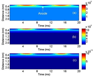
Hole densities near the anode under different AC voltage amplitudes are shown in Fig. 4. It can be seen that even when the AC voltage peak is 2 kV, there is hole layer generated near the anode at 5 ms and 15 ms. It is because the hole injection barrier is smaller than electron injection barrier, more holes are injected from the anode under the same electric field than electrons from the cathode. When the AC voltage peak is 6 kV, the maximum of hole density is 1.0×10¹⁰ m-3. When the AC voltage peak is 10 kV, the maximum of hole density is 1.0×10¹¹ m-3. The thickness of the hole layer is about 0.4 nm. It is indicated that the amplitude has strong effects on space charge dynamics in polyethylene. However, as the frequency is 50 Hz, the influence is maintained only at the positive and negative peak voltage.
Fig. 1Electroluminescence intensities under different AC voltage amplitudes
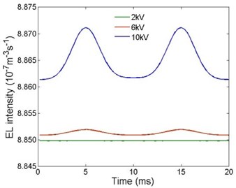
Fig. 2Current densities under different AC voltage amplitudes
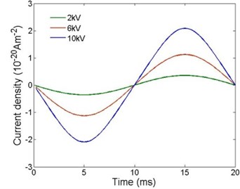
Fig. 3Electron densities under different AC voltage amplitudes: a) 2 kV, b) 6 kV and c) 10 kV
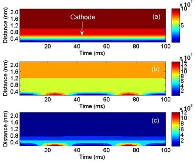
Fig. 4Hole densities under different AC voltage amplitudes: a) 2 kV, b) 6 kV and c) 10 kV
3.2. Effects of frequency
Electroluminescence intensities under different frequencies are shown in Fig. 5. It can be seen that electroluminescence intensities are the same when the frequencies are 50 Hz and 100 Hz, and there is a slight difference between 10 Hz and 50 Hz when the phase angle is 0° and 180°.
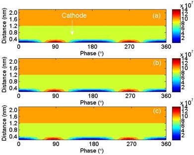
Current densities under different frequencies are shown in Fig. 6. It can be seen that the current density are almost the same under different frequencies. Electron densities under different frequencies are shown in Fig. 7. The current densities are also the same under different frequencies. It is indicated that when the frequency reaches the order of ten, the frequency has no effects on space charge accumulation in polyethylene when AC voltage is applied.
Fig. 5Electroluminescence intensities under different frequencies
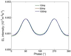
Fig. 6Current densities under different frequencies
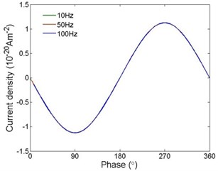
Fig. 7Electron densities under different frequencies: a) 10 Hz, b) 50 Hz and c) 100 Hz
4. Conclusions
Space charge behaviors in polyethylene when AC voltage is applied are simulated based on bipolar model assuming Schottky injection. The effects of AC voltage amplitude and frequency on current densities, electroluminescence intensities and space charge densities are investigated. It is found that the carrier densities increase with the increase of the AC voltage amplitude, but the thickness of the space charge layer changed a little. When the frequency reaches the order of ten, the frequency has no effects on space charge behaviors in polyethylene.
References
-
Boufayed F., Teyssèdre G., Laurent C., Le Roy S., Dissado L., Ségur P., Montanari G. C. Models of bipolar charge transport in polyethylene. Journal of Applied Physics, Vol. 100, Issue 10, 2006, p. 104105.
-
Cai X., Wang X., Pang D., Zou X., Yu J., Lu Z. Investigation of current densities, recombination rate and space charge density in polyethylene in thin films based on bipolar charge transport model. Materials Research Express, Vol. 6, Issue 9, 2019, p. 096451.
-
Le Roy S., Teyssedre G., Laurent C. Charge transport and dissipative processes in insulating polymers: experiments and model. IEEE Transactions on Dielectrics and Electrical Insulation, Vol. 12, Issue 4, 2005, p. 644-654.
-
Le Roy S., Teyssedre G., Laurent C., Montanari G. C., Palmieri F. Description of charge transport in polyethylene using a fluid model with a constant mobility: fitting model and experiments. Journal of Physics D: Applied Physics, Vol. 39, Issue 7, 2006, p. 1427-1436.
-
Le Roy S., Teyssedre G., Laurent C. Numerical methods in the simulation of charge transport in solid dielectrics. IEEE Transactions on Dielectrics and Electrical Insulation, Vol. 13, Issue 2, 2006, p. 239-246.
-
Teyssedre G., Vu T. T., Laurent C. Negative differential mobility for negative carriers as revealed by space charge measurements on crosslinked polyethylene insulated model cable. Applied Physics Letter, Vol. 107, Issue 25, 2015, p. 252901.
-
Baudoin F., Laurent C., Teyssedre G., Le Roy S. Charge packets modeling in polyethylene. Applied Physics Letter, Vol. 104, Issue 15, 2014, p. 152901.
-
Tian J., Zhou Y., Wang Y. Simulation of space charge dynamics in low density polyethylene under external electric field and injection barrier heights using discontinuous Galerkin method. IEEE Transactions on Dielectrics and Electrical Insulation, Vol. 18, Issue 5, 2011, p. 1374-1382.
-
Min D., Wang W., Li S. Numerical analysis of space charge accumulation and conduction properties in LDPE nanodielectrics. IEEE Transactions on Dielectrics and Electrical Insulation, Vol. 22, Issue 3, 2015, p. 1483-1491.
-
Thomas C., Teyssèdre G., Laurent C. Space charge measurements in low-density polyethylene under AC stress by the pulsed electro-acoustic method. Annal Report Conference on Electrical Insulationand Dielectric Phenomenon, Quebec, Canada, 2008, p. 325-328.
-
Le Roy S., Baudoin F., Griseri V., Laurent C., Teyssèdre G. Space charge modeling in electron-beam irradiated polyethylene: fitting model and experiments. Journal of Applied Physics, Vol. 112, Issue 2, 2012, p. 023704.
-
Laurent C., Teyssèdre G., Montanari G. C. Time resolved space charge and electroluminescence measurements in polyethylene under ac stress. IEEE Transactions on Dielectrics and Electrical Insulation, Vol. 11, Issue 4, 2004, p. 554-560.
-
Baudoin F., Mills D., Lewin P., Le Roy S., Teyssèdre G., Laurent C. Modeling electroluminescence in insulating polymers under ac stress: effect of excitation waveform. Journal of Physics D: Applied Physics, Vol. 44, Issue 16, 2011, p. 165402.
-
Zhao J., Xu Z., Chen G., Lewin P. Numerical description of space charge in polyethylene under AC electric fields. Journal of Applied Physics, Vol. 108, Issue 12, 2010, p. 124107.
About this article

The work was supported by the Science and Technology Project of State Grid Jilin Electric Power Limited Company under the Grant 2018-01.
