Abstract
Electrostatic electret generator has attracted a lot of attention in recent years, but their low power density cannot be ignored. Based on the existing research, this paper increases its power density from two aspects, including in-plane and in-space aspects. In the plane aspect, through simulation analysis, we can draw a conclusion that the output power can be increased effectively by using the bipolar charging method. From the perspective of space, the power density can be increased several times by connecting the output ends of the multi-layer generation structure. By integrating the method into the electrostatic electret generator, the power output can be effectively increased, which is suitable to the application of higher energy requirements in the specific field and a certain application prospect.
1. Introduction
In recent years, microelectronics technology and Internet of Things technology have been developing rapidly. At the same time, 5G technology has gradually entered human society, and more and more micro sensors will be in every corner of the human world. In the face of a large number of wireless sensors with very low power consumption, the mode of a high-power grid using traditional energy sources is obviously not suitable. So far, there is no good solution to the problem of battery pollution and its longevity. To this end, the scientists propose the idea of small energy harvesting to solve the large-scale power supply.
The definition of energy harvesting refers to the technology to convert relatively weak energy (usually available energy such as light energy, mechanical kinetic energy, and heat energy, etc.) into electrical energy, which is supplied to the back-end sensor for use. In the current research, the mechanical energy collection method can be divided into three types according to its working principle: electromagnetic energy collection, piezoelectric energy collection, and electrostatic energy collection [1-12].
For electrostatic induction generators, the main mechanical energy collection methods are changing the contact area and distance. For changing the spacing, vibration, compression, tension and other modes of motion can be used. The open circuit voltage waveform with varying spacing is usually in the form of a pulse, and the output pulse width is small. Most of them can only be used as sensors. The change of contact area includes the sliding and rotating modes of the plane, wherein the rotating mode can continuously output a stable open-circuit voltage so as to meet the power supply of the sensor at the back end. Rotary electrostatic generators are mainly divided into disk generators and cylindrical generators.
The characteristics of the rotary disk generator [13] are as follows: the rotary generator has a disk structure, two disks are concentric, and the disks are divided into multiple sectors that can rotate around the axis. When the two disks rotate relative to each other, due to the different positions of the two disks, when the rotor rotates at a certain angle, each fan on the stator will induce charges due to relative movement. The characteristics of a cylindrical rotary generator [14] are as follows: the rotating structure consists of a cylindrical shaft with a concentric fixed cylindrical shell. The surface of the cylindrical shaft and the inner surface of the cylindrical shell is affixed with a copper electrode grid processed by PCB. When the rotor rotates relative to the cylindrical shell, the potential difference between the two plates will be generated due to the different positions of the grid. Compared with the disk structure, the cylindrical structure can better control the spacing, and because there is more surface area, the output electrode can induce more charge, which makes the output performance and the output waveform more stable. The characteristics of the above generation modes and structures are compared and analyzed. The cylindrical rotary electrostatic generator is selected in this paper.
2. Device description
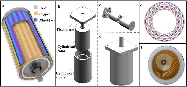
As shown in Fig. 1(a), we designed a cylindrical electrostatic generator based on an integrated structural model. As is shown in Fig. 1(b-d), the model is divided into a fixed plate, cylindrical rotor and cylindrical stator. The fixed plate is used for connection with the motor and the cylindrical stator. The cylindrical stator contains two cylindrical layers for attaching metal grids; The cylindrical rotor also contains two cylindrical layers for attaching the electret film. When the rotor and stator are assembled together, a total of four layers of coaxial cylindrical shape are arranged from the inside to out, with a total of three layers of power generation structure. We designed the stator and rotor as a whole, which has the advantage of reducing the suspension distance between the stator and the rotor. In order to ensure coaxiality, a bearing is added at both ends of the stator to match with the rotor. The use of bearings makes the distance between layers easier to control, but also makes the damping of rotation becomes smaller. As shown in Fig. 1(e), we used FEP (Fluorinated ethylene) as electret material, taking the single-layer power generation structure as an example. We pasted an electret film on the inside face of the outer cylindrical shell and charged the film bipolar using corona polarization. The purple and blue parts in Fig. 1(e) represent the positive and negative charge regions, respectively. At the same time, we paste metal grids on the outer surface of the inner cylindrical stator, corresponding to the yellow area in Fig. 1(e). Fig. 1(f) shows the completed cylindrical stator structure.
Fig. 1a) Exterior and partial sectional view of the generator, b) vertical explosion diagram of the generator, c) lateral explosion diagram of the generator, d) assembly drawing of the generator, e) cross-section of three-layer power generation structure (from inside to outside: Layer 1, Layer 2, Layer 3), f) Interdigital electrodes affixed to the inner surface of the stator
3. Working principle
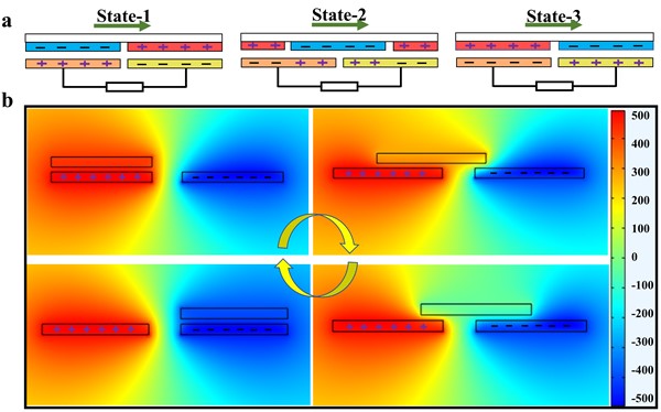
For the bipolar model, we use corona polarization method to alternately charge the electret film with positive and negative charges. The positive charge region on the electret film will induce negative charges on the interdigital electrodes, and the negative charge region on the electret film will induce positive charges on the interdigital electrodes. Assuming that there are 4 charges in each sector region after charging, the maximum differences of 8 charges can be reached in the same sector region with the sliding of the freestanding layer. However, for the single charge model, the same sector region can only have a maximum of 4 charge differences in a period. It is not difficult to see that the charge transfer amount of the bipolar model is twice that of the unipolar model, so using the bipolar model can effectively improve the surface energy density of the electret generator.
The analysis is as follows: Define three states for convenience, as shown in Fig. 2(a). In state 1, the interdigital electrode overlaps with the fan-shaped area of the electret. Due to the principle of electrostatic induction, an equal amount of charge with opposite polarity to the electret charge is induced on the electrode. In state 2, the negative charge region overlaps with the two electrode regions at the same time and generates electrostatic induction. Therefore, positive charges of different amounts on the two electrodes are accompanied by the charge flow between the electrodes, thus forming a current. In state 3, when the fan-shaped area of the rotor and stator is completely overlapped again, the charge difference reaches the maximum, and the open-circuit voltage reaches the maximum without induced current.
Fig. 2a) Power generation process under bipolar model, b) simulation of power generation principle
If the number of layers can be continued to increase within the thickness of the layers, the power generated by the generator in a large volume will be much higher, that is to say, the energy density will be increased. Set the number of layers as , the open circuit voltage of multi-layer structure as , and the open circuit voltage value of single-layer structure as , which can be expressed as:
And the output power can be expressed as:
At the same time, by combining the bipolar model with the multi-layer structure, the bipolar charging mode can increase the open circuit voltage twice on the plane, so the open circuit voltage of the multi-layer structure can be expressed as:
And the output power can be expressed as:
In this way, surface power density and volume power density have been increased.
COMSOL software was used to simulate the bipolar model, as shown in Fig. 2(b). A paranoid voltage is placed on each of the two plates and an electric field is generated around the plates. When a plate slides parallel to the field, the charge induced on the electrode will change from +Qmax to 0 and then –Qmax. As can be seen from Fig. 2(b), there are wedge-shaped transition regions between the positive and negative charges, indicating that the interdigital electrode's voltage is constantly changing as it moves.
4. Output performance
In order to test the electrical output, we connect the output ends of the three-layer power generation structure together. As is shown in Fig. 3(a), the open-circuit voltage is tested at different rotational speeds and a curve of the approximately linear relationship is obtained. While the speed increases, the open circuit voltage also increases. The linear degree of the curve is about 98.5 % after a one-time fitting.
Fig. 3a) Open circuit voltage at different speeds, b) open circuit voltage at different layers, c) output power at different layers, d) power density at different layers
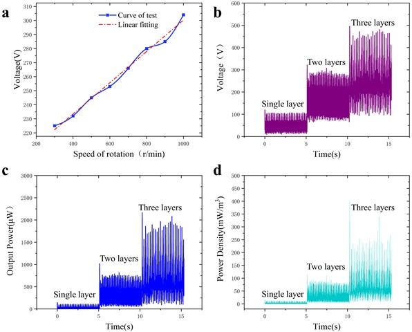
Fig. 3(b) shows the result of the open-circuit voltage test. The impedance is set at 100 MΩ and the speed is 300 r/min. As the number of layers increases, the open-circuit voltage also increases. The peak open-circuit voltage of a single-layer can reach 100 V, two layers can reach 250 V, and three layers can reach 350 V (calculated as the average waveform). In case of the spacing between layers is not controlled equally, there are some single spikes in the waveform in the figure.
Fig. 3(c) shows the test result of output power. The power of the innermost layer is measured and its power is 0.1 mW. Connected with the two-layers power generation structure, its power can reach 0.63 mW, which is 5 times higher than the first layer, and connected with the three-layers power generation structure, which can directly reach 1.2 mW.
Fig. 3(d) shows the measurement result of physical mass density at the same volume. The outer diameter of the device is 0.05 m, the height is 0.06 m. By means of testing and calculation, it can be obtained that the power density of a single-layer can reach 10.62 mW/m3, the power density of the two-layers can reach 66.9 mW/m3, and the power density of the three-layers can reach 130 mW/m3. Moreover, the physical density of the unit is increased by 11 times.
Fig. 4Impedance measurement and application: a) impedance matching test, b) voltage curve for charging the 2.2 μf capacitor, c) platform construction: rectifier of the output AC and subsequent application, d) further test: use the rectified DC to light 30 LED lights under the condition of 997 r/min
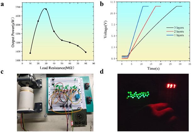
Fig. 4(a) shows the results of impedance matching. It can be seen that the optimal load resistance is about 30 MΩ and the maximum output power is about 1.7 mW. After that, the capacitor (2.2 μF) is charged by the output power, as shown in Fig. 4(b). Adjust the motor speed to 300 r/min and connect the output terminals of single-layer, two-layers and three-layers, respectively, for charging test. When charging to 12V, the charging time is gradually shortened as the number of layers increases. Connecting to the three-layers output takes only 7 seconds to charge to 12 V. Fig. 4(c) shows the experiment platform, which mainly includes the generator, rectifier circuit, LED, etc. Fig. 4(d) shows the energy supply experiment for LED, etc. It can be seen that 30 LED bulbs can be successfully lit after the AC output from three layers passes through the rectification circuit.
5. Conclusions
In conclusion, a cylindrical electret generator is developed in this paper. In order to solve the problem of the low energy density of electrostatic induction generator, the surface power density is increased by using the method of bipolar charging. By employing the multi-layer power generation structure, the volume power density has been increased. By using the bipolar charging method, the open-circuit voltage can be doubled theoretically, and the output power can be increased nearly by 4 times. With the multi-layer power generation structure, the output power density can be increased by 11 times with each additional layer.
References
-
K. Tao et al., “Ultra‐sensitive, deformable, and transparent triboelectric tactile sensor based on micro‐pyramid patterned ionic hydrogel for interactive human-machine interfaces,” Advanced Science, Vol. 9, No. 10, p. 2104168, Apr. 2022, https://doi.org/10.1002/advs.202104168
-
D. Han and K.-S. Yun, “Piezoelectric energy harvester using mechanical frequency up conversion for operation at low-level accelerations and low-frequency vibration,” Microsystem Technologies, Vol. 21, No. 8, pp. 1669–1676, Aug. 2015, https://doi.org/10.1007/s00542-014-2261-1
-
K. Li, Q. He, J. Wang, Z. Zhou, and X. Li, “Wearable energy harvesters generating electricity from low-frequency human limb movement,” Microsystems and Nanoengineering, Vol. 4, No. 1, pp. 1–13, Sep. 2018, https://doi.org/10.1038/s41378-018-0024-3
-
H. Liu et al., “A non-resonant rotational electromagnetic energy harvester for low-frequency and irregular human motion,” Applied Physics Letters, Vol. 113, No. 20, p. 203901, Nov. 2018, https://doi.org/10.1063/1.5053945
-
K. Tao et al., “Piezoelectric ZnO thin films for 2DOF MEMS vibrational energy harvesting,” Surface and Coatings Technology, Vol. 359, pp. 289–295, Feb. 2019, https://doi.org/10.1016/j.surfcoat.2018.11.102
-
L. Zhao et al., “Design, modeling and experimental investigation of a magnetically modulated rotational energy harvester for low frequency and irregular vibration,” Science China Technological Sciences, Vol. 63, No. 10, pp. 2051–2062, Oct. 2020, https://doi.org/10.1007/s11431-020-1595-x
-
Y. Zhang et al., “Rotational electromagnetic energy harvester for human motion application at low frequency,” Applied Physics Letters, Vol. 116, No. 5, p. 053902, Feb. 2020, https://doi.org/10.1063/1.5142575
-
M. A. Halim, R. Rantz, Q. Zhang, L. Gu, K. Yang, and S. Roundy, “An electromagnetic rotational energy harvester using sprung eccentric rotor, driven by pseudo-walking motion,” Applied Energy, Vol. 217, pp. 66–74, May 2018, https://doi.org/10.1016/j.apenergy.2018.02.093
-
N. Zhou, Y. Zhang, C. R. Bowen, and J. Cao, “A stacked electromagnetic energy harvester with frequency up-conversion for swing motion,” Applied Physics Letters, Vol. 117, No. 16, p. 163904, Oct. 2020, https://doi.org/10.1063/5.0025520
-
K. Tao et al., “Hierarchical honeycomb-structured electret/triboelectric nanogenerator for biomechanical and morphing wing energy harvesting,” Nano-Micro Letters, Vol. 13, No. 1, pp. 1–16, Dec. 2021, https://doi.org/10.1007/s40820-021-00644-0
-
K. Tao et al., “Origami-inspired electret-based triboelectric generator for biomechanical and ocean wave energy harvesting,” Nano Energy, Vol. 67, p. 104197, Jan. 2020, https://doi.org/10.1016/j.nanoen.2019.104197
-
K. Tao, L. Tang, J. Wu, S. W. Lye, H. Chang, and J. Miao, “Investigation of multimodal electret-based MEMS energy harvester with impact-induced nonlinearity,” Journal of Microelectromechanical Systems, Vol. 27, No. 2, pp. 276–288, Apr. 2018, https://doi.org/10.1109/jmems.2018.2792686
-
L. Lin, S. Wang, S. Niu, C. Liu, Y. Xie, and Z. L. Wang, “Noncontact free-rotating disk triboelectric nanogenerator as a sustainable energy harvester and self-powered mechanical sensor,” ACS Applied Materials and Interfaces, Vol. 6, No. 4, pp. 3031–3038, Feb. 2014, https://doi.org/10.1021/am405637s
-
Z. Zhao, H. Zhou, Y. Li, H. Chang, W. Yuan, and K. Tao, “Multiphase bipolar electret rotary generator for energy harvesting and rotation monitoring,” Journal of Microelectromechanical Systems, Vol. 31, No. 6, pp. 960–970, Dec. 2022, https://doi.org/10.1109/jmems.2022.3200461
About this article

This research was supported by the Foundations of State Grid Corporation of China under Grant No. J2022031 (New IoT sensing technology and equipment for power equipment).
The datasets generated during and/or analyzed during the current study are available from the corresponding author on reasonable request.
The authors declare that they have no conflict of interest.
