Abstract
In this study, 5.5-kW 1500 rpm IEC-60034-30-1:2014-IE4 super premium efficiency class Line Start Permanent Magnet Synchronous Motor (LS-PMSM) was presented with an innovative rotor design utilizing two different slot types have been used. The slots offered in two different geometries make a significant contribution to the motor in the form of a high starting torque thus increasing the synchronization ability. The prototype was manufactured for the optimal model obtained via analytical methods and Finite Element Software. Torque ripples that pose an important issue for permanent magnet motors were tried to be reduced by way of a skewed stator structure. In addition, motor frame and stator main dimensions were acquired from a standard IE2 induction motor design during the manufacturing of the prototype. Experimental studies for the suggested LS-PMSM topology put forth a 6 % higher efficiency in comparison with low efficiency IE2 standard induction motors with the same shaft power. Results for the starting performance, torque ripples and back-EMF were presented for the prototype motor under a constant load of 0-1.25 p.u. It was verified as a result of the study that LS-PMSMs can be used as an alternative to induction motors in pump and fan industrial applications.
Highlights
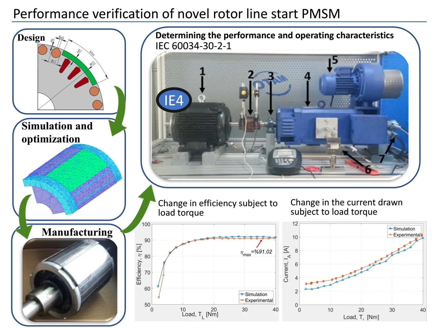
- The study focuses on the assessment of the test studies carried out in accordance with the IEC 60034-30-2-1 standard for determining the performance and operating characteristics of the manufactured LS-PMSM prototype.
- In this study, 5.5-kW 1500 rpm IEC-60034-30-1:2014-IE4 super premium efficiency class Line Start Permanent Magnet Synchronous Motor (LS-PMSM) was presented with an innovative rotor design utilizing two different slot types have been used.
- The starting performance of the motor subject to starting performance tests under constant load is sufficient for industrial applications for operating conditions of up to the nominal load.
- The study put forth that the tested innovative rotor topology can be used for improving motor efficiency of low efficiency motors based on the condition that the stator main dimensions (inner diameter and lamination length) are in accordance.
1. Introduction
Testing the performance of electrical motors and determining their efficiency are quite sensitive issues. The hardware used, environmental variables (ambient temperature, humidity etc.) and the capability of the personnel carrying out the tests have direct impacts on the variables and hence an arrangement is made for these variables with the IEC 60034-30-2-1 standard [1].
The first LS-PMSM design was suggested in 1955 by Merril under the name of Permasyn motor [2]. Researchers such as Dougles, Cahill and Adkins, and Yates also carried out studies in later years suggesting different topologies. [3-6]. Previous research on LS-PMSM increased following studies by Binns but have not reached the desired level due to the high cost related with high-performance PMs [7-8]. However, such PMs can be marketed at reasonable costs with today’s technology. Hence, it has now become possible to market LS-PMSMs as an alternative to Asynchronous Motors (ASMs) [9-11].
These motors that are characteristically quite similar with ASMs can start like ASMs but are able to operate in the synchronous regime after reaching the synchronous speed. The suggested design was prototyped in the present study [12] and performance assessment was carried out in accordance with IEC 60034-2-1 standard. Direct measurement method defined as Method A in IEC 60034-30-2-1 was used for determining motor efficiency [13].
2. Prototyped line start PMSM topology
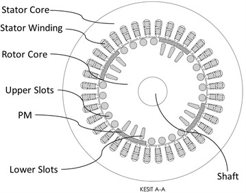
The suggested motor design was taken as reference during the present study [12] (The Fig. 1). A total of 16 NEMA D class slots with high performance at motor start were placed on the sides of the PM taking into consideration the LS-PMSM speeding characteristic of the rotor taken as reference. In addition, 12 NEMA B class closed slots were placed below the PM to provide motor start support for helping resynchronization for cases when the motor drops off synchronous speed during steady state operation.
Stator design was taken from a 5.5 kW IE2 ASM at IEC 60034-30-1 standard that is already in the market. Moreover, the stator was manufactured with an optimal skew angle of 13° taking into consideration the study by [12].
Fig. 1Reference motor design
3. Manufacturing
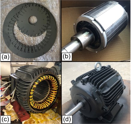
LS-PMSMs have the same stator structure with ASM. Hence, the same motor frame, motor covers and cooling fan can be used in both motor types. The motor frame and stator core sheet metal were obtained from the ASM with 4 poles IE2 5.5kW 132s-4 of a local motor manufacturer for reducing the cost of prototype manufacturing (The Fig. 2).
Fig. 2Manufacturing stages for the test motor: a) stator and rotor plates manufactured using M330 50A type steel; b) stator manufactured with a skew angle of 13°; c) rotor (PM assembly completed); d) manufactured prototype
4. Experimental study
The present section focuses on the assessment of the test studies carried out in accordance with the IEC 60034-30-2-1 standard for determining the performance and operating characteristics of the manufactured LS-PMSM prototype. In this scope, studies have been carried out for determining the motor winding resistance, steady state – transient regime performance at different load profiles, motor efficiency and power factor. The required safety measures were taken prior to starting the tests and the terminal connections were made for the motor. In addition, shaft alignment was made between the prototype and the load motor in order to obtain accurate test data. All tests were repeated 3 times for ensuring the reliability of the results. The mean values were calculated for the evaluation of the obtained results.
4.1. Test hardware
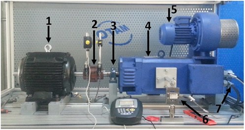
A computer-controlled test setup with a single load motor enabling motor loading was used during the tests. A slide fixture was placed at the center of the test unit located on the aluminum sigma profile bench providing mutual connection of the load motor and the test motor along the same axis. The Fig. 3 presents the manufactured prototype connected to the test area. As can be seen in the Fig. 3, the test unit has a closed working area that facilitates the mutual connection of the test motor (1) and the load motor (4). The working area includes a DC current with a shaft power of 10 kW that takes on the duty of the load during the tests (4). The maximum rpm of the DC load motor is 4000 rpm, nominal torque is 42 Nm in 2270 rpm. The DC motor has a cooling unit with internal radial fan (5), an encoder coupled to the motor for measuring motor rpm Baumer EIL580 1024 pulse/rpm (7) and a torque sensor (6). An IP66 class load cell connected to the motor frame with a torque arm that can operate in the 300°C – +700°C interval with a measurement interval of up to 100 Nm was used as the torque sensor. The force generated on the motor frame with rotational degrees of freedom along the shaft axis (by way of a sliding bearing shown with (3) is transferred to the load cell via the torque arm connected to the motor frame.
Fig. 3Test setup: 1 – test motor; 2 – laser shaft alignment tool; 3 – sliding bearing; 4 – load motor; 5 – internal radial fan; 6 – torque sensor; 7 – encoder
4.2. Determination of the test method and performance
The motor was operated at different load profiles during the tests and high-resolution data were recorded for torque, current, voltage, rpm and position. Motor starting performance, efficiency, power factor and current regime in the transient and steady state regimes were tried to be determined in the light of the acquired data. Moreover, efforts for determining the back-EMF were also included in the tests. The motor was heated up to the operating temperature of 75 °C prior to starting the data recording during the tests conducted for determining the steady state performance and it was made sure that there was no change of more than 1°C in the motor temperature for half an hour.
The motor was tested for each load during the start performance tests from unloaded operation up to 40 Nm at intervals of 5 Nm. In addition, the load of the test motor operating in the steady state regime was increased up to 40 Nm by intervals of 2 Nm and the motor synchronous operating characteristics were examined separately for each load in order to understand the synchronous operating characteristic better. The prototype motor was accelerated up to 1500 rpm by using the PM machine in the test setup when obtaining back-EMF. The voltage induced at the winding tips was recorded at high resolution throughout the test duration.
In addition to the tests carried out, efforts were put in for determining the synchronization performance of the motor at the steady state operating regime following a sudden increase and decrease in load. The load for the motor operating under nominal load was decreased suddenly down to 25 Nm during motor load decrease tests. Whereas the load for the motor operating under nominal load was increased suddenly up to 40 Nm during loading tests.
5. Results and discussion
After line start, LS-PMSMs have to overcome the braking torque generated by the PMs in the rotor in addition to the motor load torque and motor inertia. Moreover, motor inertia and mechanical losses should also be taken into consideration. These factors that are effective on motor start also have adverse impacts. The PMs in LS-PMSMs that cannot start in a short amount of time may be subject to thermal and magnetic demagnetization. Therefore, the motor starting regime should be examined in detail. Moreover, the torque quality in the steady state regime for such motors is another issue that should be taken into consideration. This section of the study puts forth the results acquired from experimental studies with the test motor. The obtained results were also compared with the analysis results for the finite elements model presented in Zohra et al. [12].
5.1. Constant load experiments
The test motor was tested separately for each constant load from the transient state until reaching the synchronous speed at loads ranging from no load up to 40 Nm at intervals of 5 Nm. The power, current, power factor, efficiency, torque etc. data for the motor were recorded throughout the test period. The changes in efficiency and power factor were examined subject to the output power in the light of the acquired data.
Fig. 4Motor starting performance under different loads
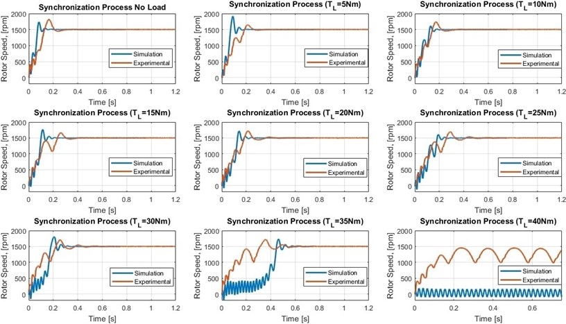
The graphs in the Fig. 4 present the starting performance curves as a result of the loads. The graphs also include the data acquired via FEM analysis. As can be understood from the graphs, the motor could be synchronized at most around 0,6 s for loads of up to 35 Nm (full load). Values below 1 s are quite satisfactory for industrial applications. It can also be observed that the motor displays a greater performance with increasing load based on the experimental data in comparison with the analysis data. It was observed that the 40 Nm motor could not be synchronized during the starting test in both the experimental and analysis studies. Long synchronization times of LS-PMSMs may lead to instabilities in the thermal regime of the motor leading to an increase in harmonics of the motor. This in turn makes it more difficult to estimate the operating characteristics of the motor. As can be seen from the 35 Nm and 40 Nm load graphs, increasing synchronization times were effective on FEM analysis results.
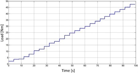
Motor load was increased in multiples of 2 Nm at specific intervals while the motor was at synchronous speed (1500 rpm) during the experiments carried out for determining the motor synchronous operating performance. Motor data such as power, current, power factor, efficiency, torque etc. were recorded for each load value (0 Nm, 2 Nm, 4 Nm…40 Nm) during synchronous operation. The changes in efficiency and power factor subject to output power were examined in the light of the acquired data. The Fig. 5 presents the data for the load torque applied to the prototype for test purposes following synchronization.
Fig. 5Load torque data applied to the prototype for test purposes after
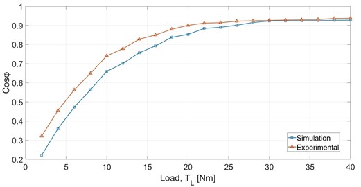
The load torque of the test motor operating without load in the steady state regime at 75 °C was increased gradually during the experimental studies for examining its operating characteristic under different loads. The graphs in the Fig. 6 illustrate the changes in the power factor as a result of the loads applied. Moreover, FEM analysis data have also been included in the graphs for comparison purposes. As can be understood from the graph, the experimental data and FEM analysis results are in accordance as the load torque increases.
Fig. 6Data for power factor obtained via experimental and FEM analysis results
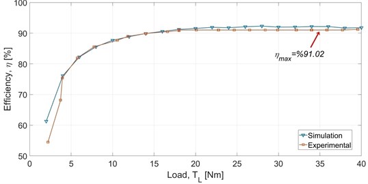
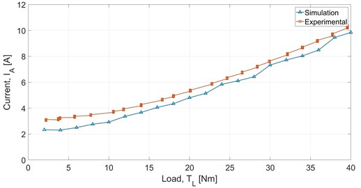
The Fig. 7 shows the change in motor efficiency and The Fig. 8 shows the change in the current drawn by the motor subject to motor load. It was observed when both graphs were examined that there is a significant accordance between the FEM analysis results and experimental data. As can be seen in the Fig. 7, highest efficiency was obtained at full load as 91.02 %. This value was determined in accordance with the direct measurement method defined in the IEC 60034-2-1 standard. IEC 60034-1 standard section 12 puts forth that motor total losses of up to 15 % are tolerated for motors with powers of 150 kW and below [14]. Accordingly, minimum motor efficiency for 5.5 kW IE4 50 Hz was calculated as = 89.53 %. The value of 91.02 % that is above the indicates that the manufactured prototype meets the 5.5 kW IE4 50 Hz base efficiency values.
Fig. 7Change in efficiency subject to load torque
While the motor was fed by an ideal 380 V voltage source during the simulations, it was connected directly to the line during the test studies. Hence, it was expected that the current drawn by the motor will be slightly higher than the simulation results due to the fluctuations in the line voltage. The change in motor current regime can be observed in the graph presented in the Fig. 8.
Fig. 8Change in the current drawn subject to load torque
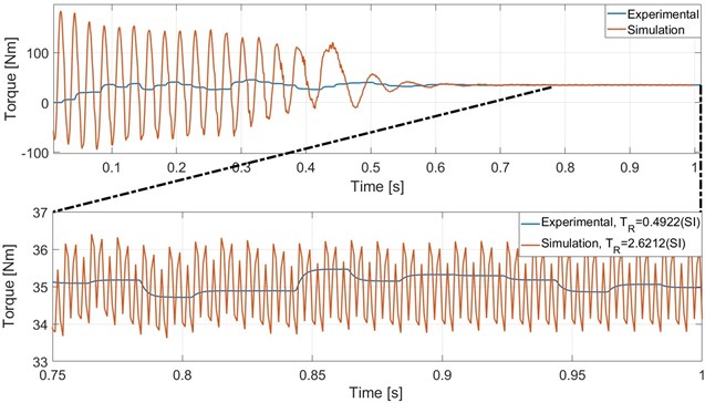
The PMs and stator teeth interacted due to the fact that the PMs are included in the rotor for LS-PMSMs leading to ripples in the motor shaft torque. These ripples have adverse impacts on the quality of the shaft torque generated by the motor [15]. The ripple ratio in the shaft torque is calculated in SI units as shown in Eq. (1). The and , in the equation denote the RMS and mean values of the motor torque respectively:
The graph in the Fig. 9 examines the torque ripples of the motor under a load of 5 Nm. As can be seen from the graph, while the ripples in the shaft torque after synchronization are determined via FEM as 2.6212 (SI), this value was calculated during experimental studies as 0.4922 (SI). However, it is possible to state that the measured torque ripples are lower than expected because the resolution of the torque sensor is not high enough.
Fig. 9Comparison of the experiment and FEM analysis results with regard to torque characteristics
5.2. Determining back-EMF and torque characteristics
The back-EMF generated by the motors with balanced winding distribution and low torque ripples is expected to put forth a regular sinusoidal profile. It is inferred for a motor with unbalanced back-EMF that the air gap flux distribution is also unbalanced and a decrease is observed in the quality of the torque generated by the motor.
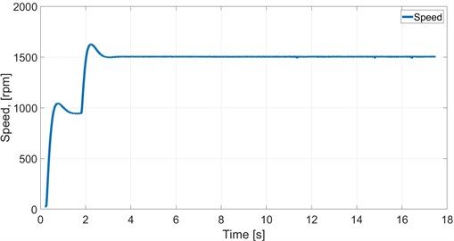
The prototype motor speed was increased up to 1500 rpm during this step of the tests as a result of using the DC machine in the test setup as the motor. Data acquisition was continued for 17 s. The speeding graph of the prototype is presented in the Fig. 10.
Fig. 10Prototype motor back-EMF test – speeding graph
The test motor is basically operated as a generator in the back-EMF test. Back-EMF voltage is induced in the stator winding tips when the stator windings cutoff the PM flux with the speeding up of the motor. The voltage value induced at the winding tips and motor speed information was obtained in high resolution externally using the National Instrument company cDAQ-9174 cabin along with NI9225 and NI9239 modules. The acquired data were recorded by an interface designed in the LabVIEW 2011 development environment. A 0.1 s section of the back-EMF measured from the winding tips as a result of the test can be seen in the Fig. 11.
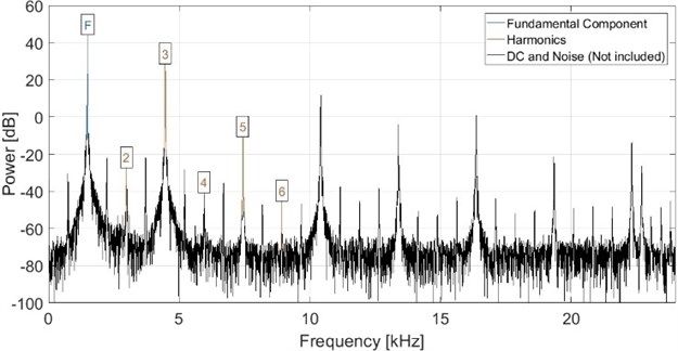
As can be seen from The Fig. 11, all three phases are regular for the voltage obtained from the winding tips. It was also found that the angle between all phases was 120°. The highest voltage induced at the winding tips was measured as UMAX = 303.3 V, RMS value was measured as 214.4 V. The graph presented in the Fig. 12 illustrates the THD value of the harmonics. The graph, consisting of the fundamental component, harmonics and unconsidered DC noise signals, it was found that the fundamental component is produced at the motor operating frequency (50 Hz). It was also set forth that the basic harmonic components are produced at the second, third, fourth, fifth and sixth levels. The THD value was calculated as –15.58.
Fig. 11Back-EMF induced at the winding
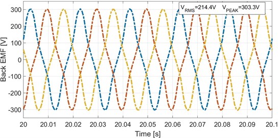
Fig. 12THD graph for the induced voltage, THD: –15.58 dB
5.3. Sudden load chance test
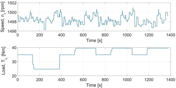
These tests were conducted for examining the impact of the sudden decrease/increase of the load of the LS-PMSM prototype on motor speed. The behavior of the prototype motor at synchronous speed was examined when the motor was suddenly dropped down (reducing the load to 25 Nm) as it was operating at a speed of 1500 rpm under a load of 35 Nm or following a sudden loading (increasing the load to 40 Nm). The Fig. 13 presents the speed characteristic with the load torque profile applied to the motor and the changing load torque of the motor. As shown in the speeding graph, the prototype motor is quite tolerant to sudden motor load changes. Therefore, it is possible to state that the steady state performance of the motor is quite high.
6. Conclusions
3D FEM analysis was used in [12] for obtaining the operating characteristics of the motor designed with skewed stator and it was determined as a result of the analyses that torque ripples were decreased down to = 2.6212 (SI) by using 13° skewed stator. It was observed as a result of the experimental studies that the skewed stator structure is successful and that the torque ripples have been decreased down to 0.4922 (SI). The efficiency was determined as 91,02 % for the motor with a unique rotor design the performance of which has been verified by experimental studies. A gain of 6.02 % was obtained in the efficiency compared with the stator design of IE2 ASM. It was observed during all stages of the studies that the motor current characteristics are within acceptable limits. The starting performance of the motor subject to starting performance tests under 2-40 Nm constant load was sufficient for industrial applications for operating conditions of up to the nominal load, but the performance under excessive load was not sufficient. The experimental results obtained as a result of the tests were mostly in compliance with the simulation results.
Fig. 13Sudden load chance experiment results
It has been verified as a result of the study that the suggested motor is more suited for applications with low load impact at starting. Indeed, it is observed that pumps and fans with this load characteristic are mostly used in industrial applications. The study put forth that the tested innovative rotor topology can be used for improving motor efficiency of low efficiency motors based on the condition that the stator main dimensions (inner diameter and lamination length) are in accordance.
The purpose of the study was to increase the efficiency of ASMs that are widely preferred in the market. For this purpose, an economic motor with average efficiency was preferred in stator design. It was put forth as a result of studies on the design of LS-PMSMs that the stator design is directly related with motor efficiency and torque characteristic. Hence, it is certain that selecting an ASM with high efficiency (IE3) for stator design shall be effective in the performance of the motor with innovative rotor design.
References
-
“Rotating Electrical Machines Part 2-1: Standard Methods for Determining Losses and Efficiency from Tests (excluding machines for traction vehicles),” Bs En 60034-2-1, 2014.
-
F. W. Merrill, “Permanent magnet excited synchronous motors,” Electrical Engineering, Vol. 74, No. 2, pp. 143–143, Feb. 1955.
-
J. F. H. Douglas, “Induction motors with permanent magnet excitation,” Electrical Engineering, Vol. 78, No. 12, pp. 1195–1195, Dec. 1959.
-
D. P. M. Cahill and B. Adkins, “The permanent-magnet synchronous motor,” Proceedings of the IEE Part A: Power Engineering, Vol. 109, No. 48, p. 483, 1962, https://doi.org/10.1049/pi-a.1962.0141
-
W. W. Yates, “Permanent Magnet Rotor,” US3492520, 1970.
-
De J. H., “Synchronous Electric Machine,” US3743873, 1971.
-
K. J. Binns, “Permanent magnet synchronous motors,” in IEE Colloquium on Permanent Magnet Machines, 1988.
-
K. J. Binns and T. M. Wong, “Analysis and performance of a high-field permanent-magnet synchronous machine,” IEE Proceedings B – Electric Power Applications, Vol. 6, No. 131, pp. 252–258, 1984, https://doi.org/10.1049/ip-b:19840038
-
B. Zöhra, “Line start radial flux permanent magnet synchronous motor design and prototype manufacturing,” Ph.D. Thesis, Tokat Gaziosmanpaşa University, Tokat, 2019.
-
M. Tumbek and S. Kesler, “Design and implementation of a low power outer-rotor line-start permanent-magnet synchronous motor for ultra-light electric vehicles,” Energies, Vol. 12, No. 16, p. 3174, Aug. 2019, https://doi.org/10.3390/en12163174
-
D. Uygun and Y. Çetinceviz, “Yüzey Yerleştirmeli Kalıcı Mıknatıslı Senkron Generatörlerin Tutma Torkunun Azaltılması İçin Stator Yapılandırması,” Gazi Üniversitesi Fen Bilimleri Dergisi Part C: Tasarım ve Teknoloji, pp. 605–620, Sep. 2018, https://doi.org/10.29109/gujsc.391395
-
B. Zöhra, M. Akar, and M. Eker, “Design of a novel line start synchronous motor rotor,” Electronics, Vol. 8, No. 1, p. 25, Dec. 2018, https://doi.org/10.3390/electronics8010025
-
E. B. Agamloh, “A comparison of direct and indirect measurement of induction motor efficiency,” in 2009 IEEE International Electric Machines and Drives Conference (IEMDC), pp. 36–42, May 2009, https://doi.org/10.1109/iemdc.2009.5075180
-
“Rotating Electrical Machines Part 1: Rating and Performance,” Bs En 60034-1, BSI Stand., 2010.
-
R. Ilka, Y. Alinejad-Beromi, and H. Yaghobi, “Cogging torque reduction of permanent magnet synchronous motor using multi-objective optimization,” Mathematics and Computers in Simulation, Vol. 153, pp. 83–95, Nov. 2018, https://doi.org/10.1016/j.matcom.2018.05.018
About this article

This study was supported by the Tokat Gaziosmanpaşa University Scientific Research Projects Unit, project number 2017/90.
